Pathfinder Solar Array/ Fall/2018
Wing Articulation with Linear Actuator
Author/s: Eduardo Charcas
Table of Contents
Introduction- Linear Actuators & Mechanical Articulation
One of the project requirements is articulating the custom solar panels which are able to track the sun and enter/exit a cocoon state. This semester, a new approach was taken with the wing articulation system instead of going with the worm gear motors and gear system that was attempted in previous semesters and which was not successfully accomplished. Some difficulties that the previous team encountered were not having a gearbox for the static gear on the panel and the worm gear from the motor, so that the motion would be tightly controlled. Many holes were drilled into the panel in an attempt to mount a static rod on which the static gear on the panel would be mounted. This semester the types of motors chosen to articulate the wings were linear actuators. Below are the specifications for the 50mm linear actuators that were purchased.
- Rated Voltage: 12V DC; Stroke size: 50mm(2 inches);
- Load Capacity: 750N(75KG/165Lbs); No-Load Speed: 10mm(0.393 inch)/sec;
- Fully Retracted Length 105mm + Stroke Size; Fully Extended Length 105mm + Stroke Size + Stroke Size;
- Limit Switch: Built-in Non-Adjustable; Low noise: db<45 (A); Duty cycle: 10%; Operational Temperature : -25~+65 ℃;
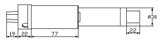
Fig 1. Linear Actuator Side View
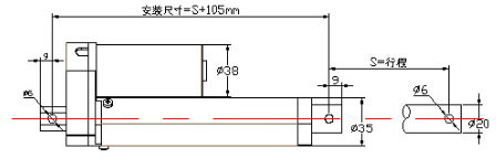
Fig 2. Linear Actuator Side View
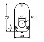
Fig 3. Linear Actuator Top View
How Linear Actuators Work:
Please see the following link for explanation and animations of how a linear actuator operates. Linear Actuator Basics
First Attempted Configuration:
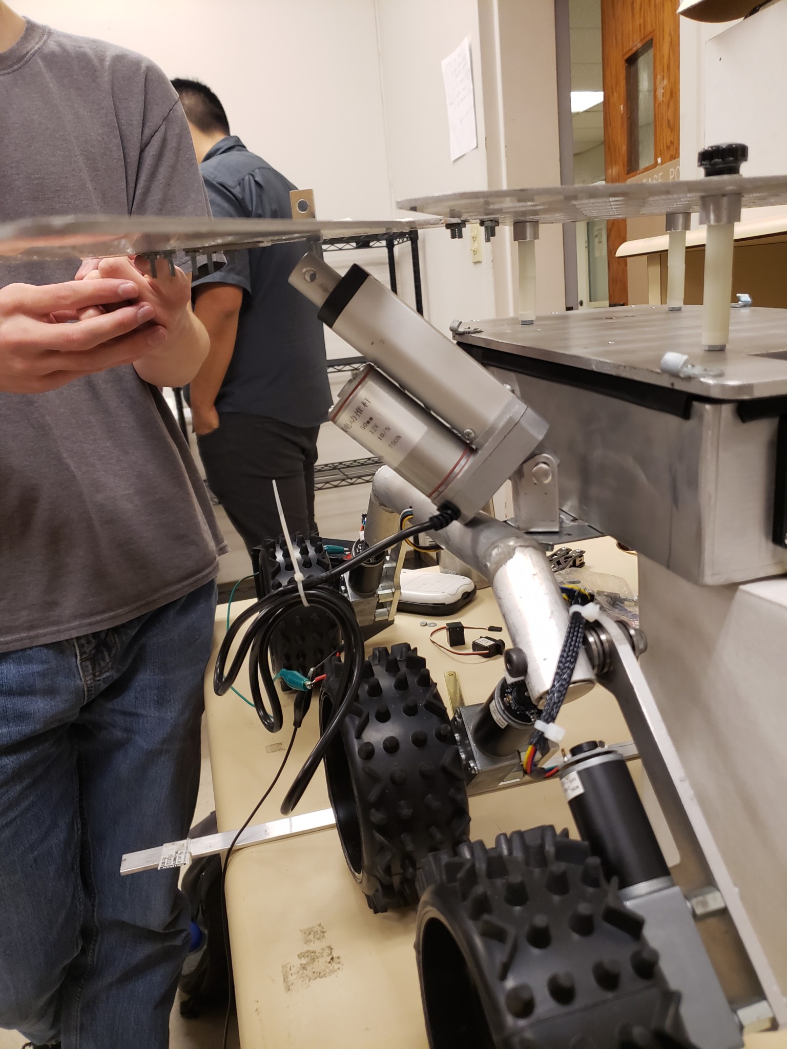
In the picture below you can see how some new hardware was added to the left, right and rear. The thought process behind this was to have the motors extend outward from a low to high position and with the help of a custom linkage system it would have articulated from approximately a twenty degree angle below horizontal to the cocoon position. Below are the calculations for the downward forces that the wings will be applying to the motors. The purchased motors are more than capable of lifting the wings with all the solar accessories attached.
Linear Actuator Force Calculation:
Linear Actuator Load Capacity: 750 Newtons or (75KG/165Lbs)
Single Wing Weight = 1.625 lbs
15 Solar cells + Wiring+Clips =0.75 lbs
15 PCB’s + 5 voltage sensors+ 5 current sensors = 0.75 lbs
Total Weight = 3.125 lbs = 1.4174 Kg
Force of Total Left or Right Wing Weight = (1.4174 Kg)(9.81m/s^2) = 13.9 Newtons
Rear Wing Weight = 0.5 lbs
9 Solar cells + Wiring+Clips =0.75 lbs
9 PCB’s + 3 voltage sensors+ 3 current sensors = 0.75 lbs
Total Weight = 1.75 lbs = 0.7937 Kg
Force of Total Rear Wing Weight = (0.7937 Kg)(9.81m/s^2) = 7.8 Newtons
Problem: Linear Actuators Too Long
There was a miscalculation with the length of the linear actuator, once mounted it was apparent that original thought of using a linkage system with the motor would not work because there was insufficient clearance, as well as the motors interfering with the suspension and restricting its motion.
Solution: Second Configuration
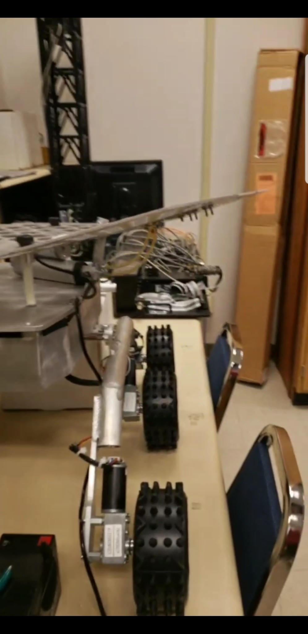
A new configuration was found with the help of the video below. By mounting the motors underneath the main panel the desired articulation was achieved. An arched hinge was purchased and custom aluminum pieces were cut and fastened with nuts and bolts to achieve this.
Below is a video of the desired operation of the wing panel articulation. Except since we are using linear motion and creating rotational motion for the wing articulation , there were some adjustments made to the design shown in the video.
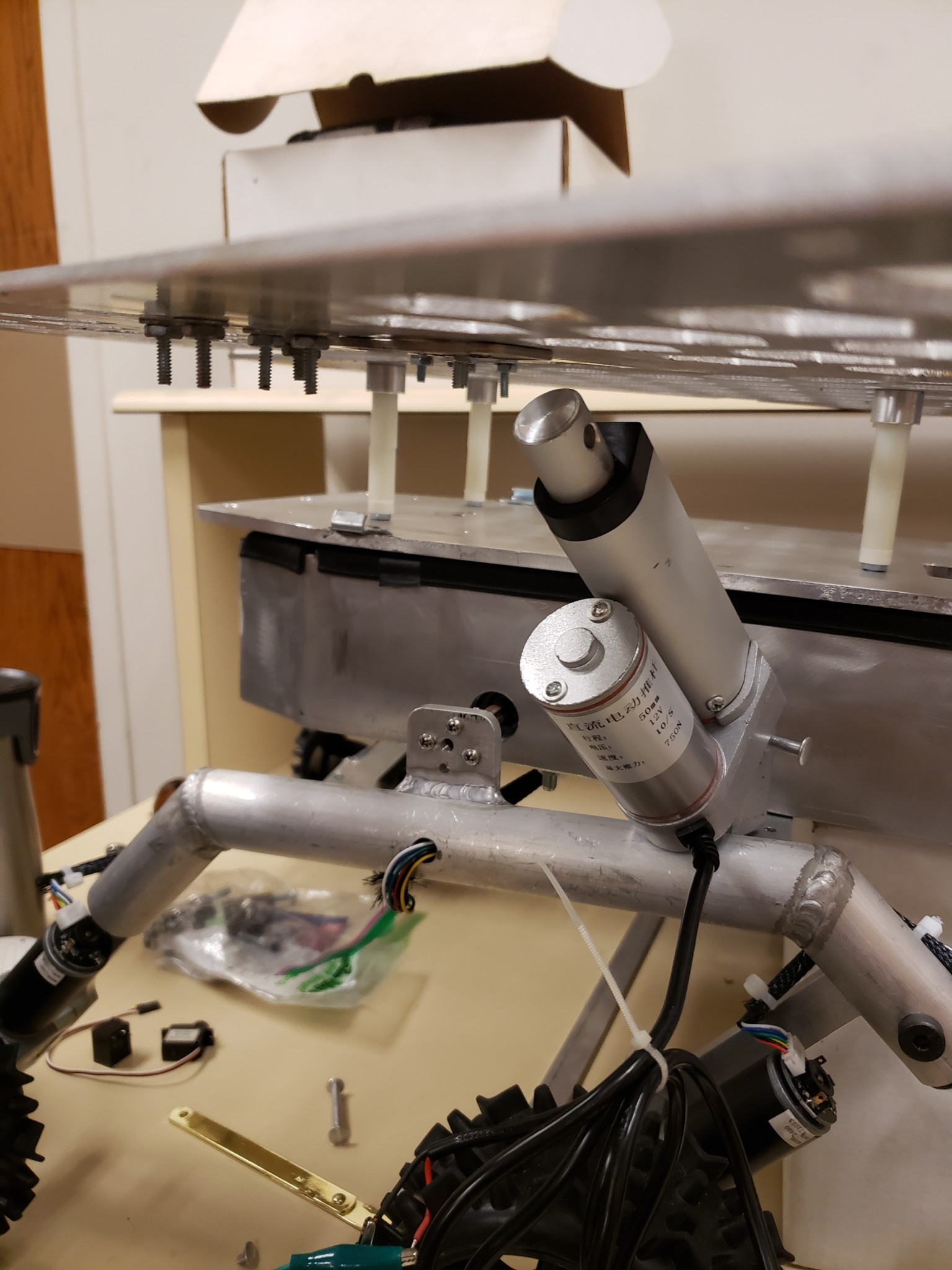
Below is a picture of the left wing with the golden arch hinge attached to the linear actuator and the wing. The linear actuator was held in place by the tightening of the main panel downward. Since this was done for proof of concept, and will be later improved.
Linear Actuator Control
Control of the linear actuator motors needs to be tuned to turn off and on at controlled times to have maximum control of the solar array wing articulation. Since the linear actuator motors need to be powered by a 12V power source, we needed a method to control them precisely with the help of the Arduino Uno board. And since the maximum voltage that the Uno board can administer is 5V, the decision was made to control them with a Arduino Uno board in conjunction with 5V Relays. Each linear actuator motor requires 2 relay channels on the relay shield module board. Since 3 linear actuators are being used, a total of 6 channels are needed. Cost wise it made more sense buying a 8 channel relay module, instead of two 4 channel or three 2 channel relays.
8-Channel 5V Relay Shield Module Board:
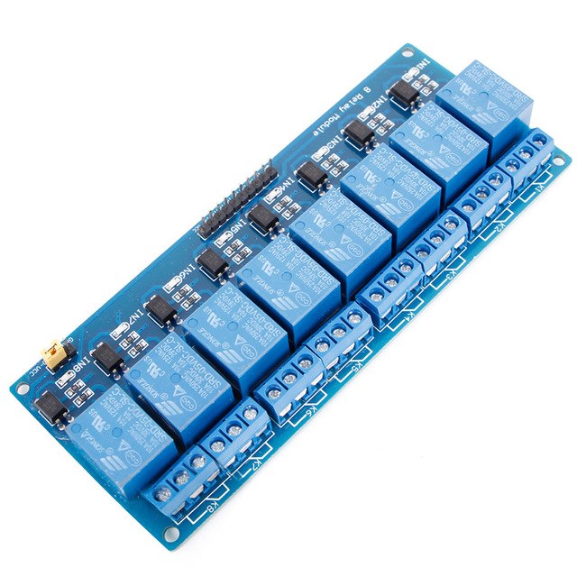
Amazon Purchase Page: 8-Channel 5V RELAY Shield Module
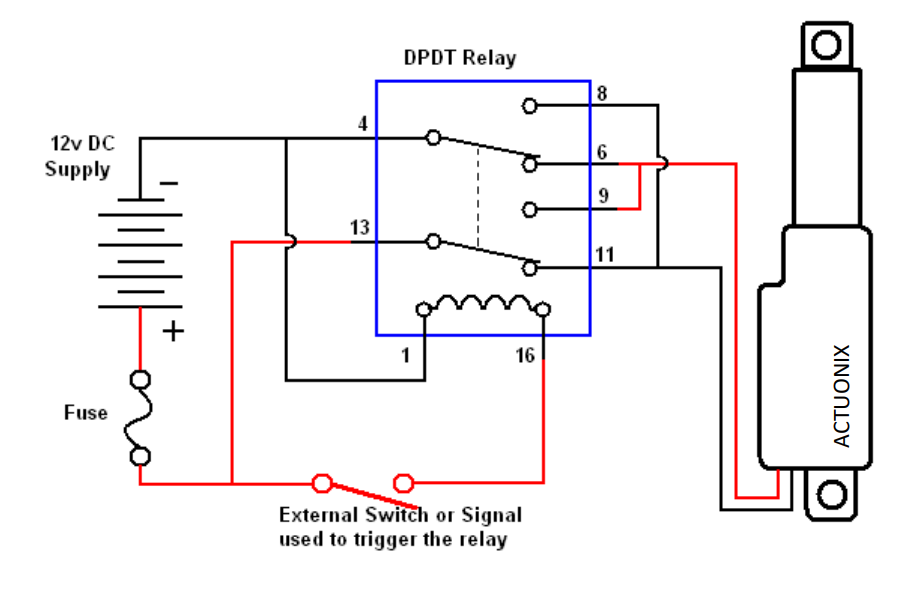
How To Connect The Relay To The Linear Actuator
Below is an instruction video of how to use the relays in conjunction with the Arduino Uno for Linear Actuator motor control.
Conclusion
To conclude, the second configuration is working for us but it still needs improvement by adding a second pivot point on the arch hinge to make the wing articulate to a cocoon state. Jeff Gomes will be consulted to see if he can offer any insight into this configuration. Another problem that will be approached will be that of how to securely mount the motors below the main panel and on top of the aluminum plate chassis cover.