ModWheels Preliminary Design Document
By: Lucas Gutierrez (Project Manager)
ModWheels Team Members:
Project Manager: Lucas Gutierrez
Mission, Systems, and Test Engineer: Andrew Yi
Electronics and Control Engineer: Matt Shellhammer
Design and Manufacturing Engineer: Adan Rodriguez
Table of Contents
Program Objectives / Mission Profile
By: Lucas Gutierrez (Project Manager)
Objective
ModWheels is a toy car that will navigate a multi-colored 2D maze using the Arxterra App for remote control. The initial phase consists of having the toy car navigate the maze with user input. ModWheels will then memorize the route taken during the initial phase and will be able to autonomously navigate the maze for the second phase. Another rule of the maze will be to detect other robots and avoid collision. These are the objectives stated by the customer.
Requirements
By: Andrew Yi (Mission, Systems, and Test Engineer)
Program Level 1 Requirements
L1-1: ModWheels shall be completed by Wednesday, December 13th, 2017.
L1-2: ModWheels will be a toy robot.
L1-3: ModWheels shall cost no more than $200.
Project Level 1 Requirements
L1-4: ModWheels will use a 3DoT board.
L1-5: ModWheels shall use a peripheral custom PCB connected to 3DoT board.
L1-6: ModWheels will be able to be controlled through the ArxRobot App or Arxterra Control Panel.
L1-7: ModWheels shall navigate a multi-colored 2D maze.
L1-8: ModWheels shall stop when another robot has been detected within a 1.5 foot radius ahead.
L1-9: ModWheels should be able to avoid collisions with other robots operating within the maze.
L1-10: ModWheels shall provide video feedback through a smartphone placed on the toy car.
L1-11: ModWheels shall weigh no more than 500 grams.
L1-12: ModWheels shall be able to memorize a path through the maze taught by the user.
L1-13: ModWheels should be able to travel down the memorized path autonomously.
L1-14: ModWheels should be able to adopt an electronic differential with dual rear motors.
L1-15: ModWheels should be able to adopt a slip differential with dual rear motors.
System & Subsystem Level 2 Requirements
L2-1: ModWheels will have a 3DoT board mounted on the chassis of the ModWheels toy car, as defined by L1-4.
L2-2: ModWheels shall use 2 color sensors to detect the walls within the maze so that it can keep itself within the confines of the hallways, as defined by L1-7.
L2-3: ModWheels shall use the ultrasonic sensors to detect other objects 1.5 feet in front of the toy car, as defined by L1-8.
L2-4: ModWheels will be controllable through Arxterra App using the HM-11 Bluetooth module on the 3DoT board. The Arxterra App has a graphical user interface (GUI) that allows control of the toy robot, as defined by L1-6.
L2-5: ModWheels should have an area for a smartphone to be placed onto it. The phone should have a periscope attachment on its camera and will provide live feed video via the Arxterra App, as defined by L1-10.
L2-6: ModWheels shall navigate a maze autonomously after it has cleared the maze with user input. The autonomous route shall follow the original route without user input, as defined by L1-12.
L2-7: ModWheels will be a remote controllable toy car with a paper shell overlay. The paper shell overlay gives the ModWheels its customizability, as defined by L1-2.
L2-8: ModWheels should use the ultrasonic sensor to reroute themselves if another robot is approaching it head on. When oncoming traffic is detected, ModWheels should direct itself closer towards a wall to allow the oncoming robot to pass, as defined by L1-9.
L2-9: ModWheels shall use a custom PCB to control the ultrasonic, infrared, and color sensors. This PCB shall be connected to the 3DoT board aboard the chassis, as defined by L1-5.
L2-10: ModWheels shall use 2 infrared (IR) sensors to detect the black lines in the maze that indicate intersections, as defined by L1-7.
L2-11: ModWheels shall stop when another robot is detected to be 1.5 feet in front of the toy car, as defined by L1-8.
L2-12: ModWheels shall cease all motor functions when another robot is detected 1.5 feet in front of it. It shall resume resume normal operations after the robot has left the detection area, as defined by L1-8.
Source Material:
Design Innovation
By: Matt Shellhammer (Electronics and Control Engineer)
Creative Design
- Rules of the maze.
- Navigating the maze with other robots traveling through at the same time across many various paths has proved to be a very elaborate ConOp. One possible solution for this problem, discussed during the forced relationship and dunker diagram activities, is creating a specific rules of the maze that will be followed by all robots in the maze to ensure that no robots collide. To establish the rules of the maze our project manager is speaking with the other project managers and trying to agree upon a standardized set of rules for the maze.
- Able to download additional maze maps quickly.
- This solution came about from the forced relationships technique trying to force a bookcase onto the ModWheels car. This brings up the task of being able to remotely drive through the maze using the Arxterra app and then being able to then repeat that path autonomously. Doing so, after changing the maze in ModWheels memory it can quickly and easily memorize and follow new mazes and routes.
- Sense other robots within the maze to avoid collisions
- Yet again, during the dunker diagram activity, one of our big concerns was navigating the maze while other robots are also within the maze. Another technique for avoiding other robots within the maze was to add a sensor, such as an ultrasonic sensor, to use to detect and avoid obstacles within the maze. We will be using an ultrasonic sensor on ModWheels to achieve this awareness.
- Making turns within the maze
- In a maze, making accurate turns is something of great importance, since a poor turn can cause you to veer off the desired path. Two different possible approaches to this problem were discussed. The first approach discussed was to design a car that has wheels that can rotate 360 degrees allowing the car to never have to turn, the wheels will rotate and the car will stay in place. Since the ModWheels chassis relatively fixed, this approach isn’t really viable, however we did discuss another more possible approach, using encoders. Both of these approaches were a result of the attributes listing creative solutions activity.
- Navigating within the maze
- To navigate throughout the maze there must be certain sensory devices on the vehicle that allow it to be aware of its surroundings. The solutions developed to help ModWheels be aware of its surroundings is IR and/or color sensors to help detect the rooms of the maze. These sensors could also later be used as an additional tool to gather information when making a turn within the maze.
Source Material:
Systems/Subsystem Design
By: Andrew Yi (Mission, Systems, and Test Engineer), Matt Shellhammer (Electronics and Control Engineer), and Lucas Gutierrez (Project Manager)
Product Breakdown Structure
By: Andrew Yi (Mission, Systems, and Test Engineer)

The ModWheels car is broken into 6 sections for the Product Breakdown Structure (PBS). The visuals consist of a smartphone with periscope attachment feeding live video back to the user. The motors, wheels, and servo are the main parts of the mobility of the toy car. Bluetooth and the Arxterra app allow for mobile control of the toy car. The color and ultrasonic sensors will aid in detecting walls (color) and robots (ultrasonic). The paper overlay and 3D printed plastic allow for customization of the ModWheels toy car. A singular 3.6V RCR123A battery will power the ModWheels car and its peripherals.
Electronic System Design
System Block Diagram
By: Andrew Yi (Mission, Systems, and Test Engineer)

The System Block Diagram (SBD) gives a visual of how the different components of a system are connected. The motor drive on the 3DoT will power the dual RWD motor, which in turn controls the rear wheels. The color sensors on the custom PCB assist in wall detection (in maze) and in detecting other robots within the maze. A periscope will be attached onto the camera of a smart phone and placed on the ModWheels car. This will give live feed video back to the user. The servo allows for turning of the front wheel and controls the steering of the toy car.
Interface Definition
By: Matt Shellhammer (Electronics and Control Engineer)
To know how all of the external components will interface with the 3DoT board the table has been created to know what connections will be required for each of the individual components. This table can then be used to configure the interface matrix between the 3DoT board and the external components.
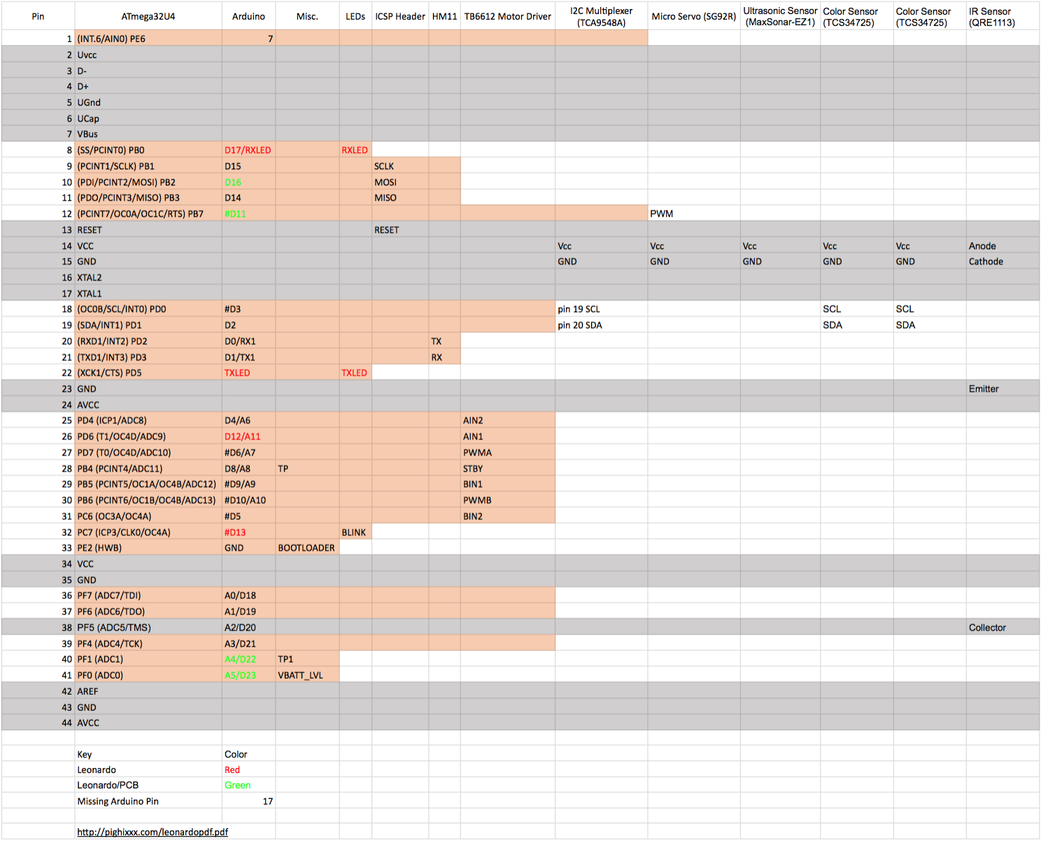
Mechanical Design
By: Lucas Gutierrez (Project Manager)
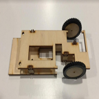
This Illustrator file shows the first and foundational model to which ModWheels will develop from. This two dimensional vector file is converted to a .dxf file which is readable by Laserworks, a software interface for the Kaitian laser cutting and engraving machine. Once correct settings in Laserworks are enabled, optimal settings for a certain material, the laser cutting and engraving machine cuts and engraves the material (1/8″ 3-ply birch) from which the car can be assembled.
Design and Unique Task Description
By: Matt Shellhammer (Electronics and Control Engineer)
Electronics and Control
- Trade study of various ultrasonic sensors to determine the best fit for our application.
- Trade study to determine if we tune two separate motors to drive straight at 40 percent power, will they continue on that same path when the power to the motors is increased (e.g. 50 percent, 60 percent, 70 percent, etc.).
- Trade study to test maze configurations (1 to 4 cells) using the 3DoT board, and determine the optimal hedge distance and ideal sensor layout.
- Perform a power system analysis to lay out a power budget for our system (determine current draw for all of the components).
- Determine configuration to be used for I2C communications.
- Create Fritzing diagram for custom PCB.
- Customize Arxterra app / dashboard for specific ModWheels applications.
- Breadboard testing of turning mechanism & sensors.
- Determine how sensors will be used for navigating the maze (e.g. line follower, wall follower, room detection).
- Develop software for: room detection, path memorization, autonomous navigation of the maze, etc.
Manufacturing
- Create Solidworks model of ModWheels chassis from the current 2D model of the ModWheels chassis.
- Design method for mounting sandblaster front wheels chassis and servo onto the current ModWheels chassis.
- Design method for mounting PCB and sensors onto the current ModWheels chassis.
- Design cell-phone mount for ModWheels chassis.
Preliminary Plan
By: Lucas Gutierrez (Project Manager)
ModWheels Team Members:
Project Manager: Lucas Gutierrez
Mission, Systems, and Test Engineer: Andrew Yi
Electronics and Control Engineer: Matt Shellhammer
- Fritzing Diagram
- Electronic Motor Study
- Printed Circuit Board (PCB) Design & Test
- 3DoT Firmware
Design and Manufacturing Engineer: Adan Rodriguez
- Eagle CAD for PCB layout
- SolidWorks for ModWheels 3D model
- Manufacture Chassis, 3D printed parts, and laser cut parts
- Assemble ModWheels
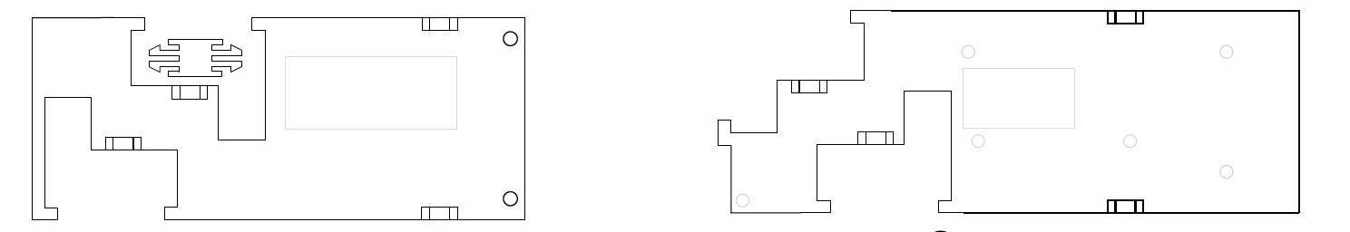
Work Breakdown Structure
By:
Project Schedule
By: Lucas Gutierrez (Project Manager)
Top Level Schedule
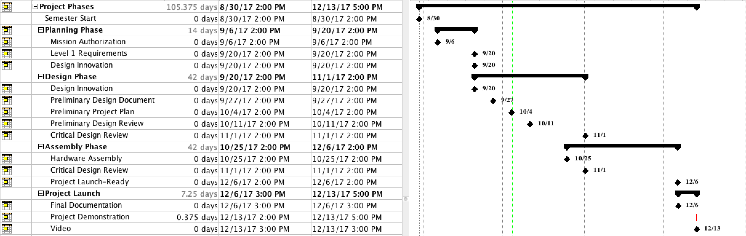
This layout provides the layout of due dates for the ModWheels project.
System/Subsytem Level Tasks
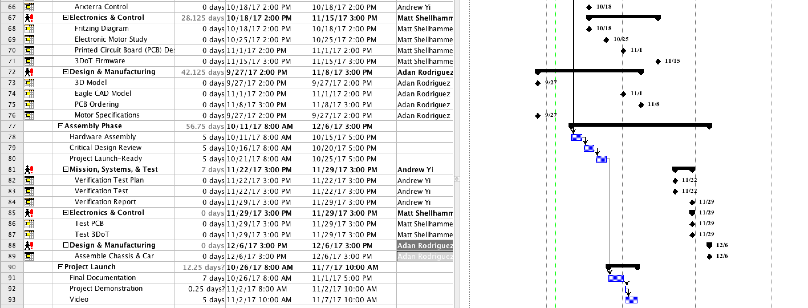
This layout provides the layout of due dates and assignments for engineers for the ModWheels project.
BurnDown Schedule
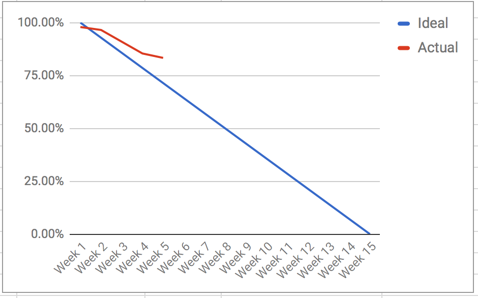
This layout provides the burn down for the ModWheels project.
Systems Resource Report
By: Andrew Yi (Mission, Systems, and Test Engineer)
Power Allocation Report

The power report is an overview of the power requirements of each physical component. The MST team is currently working with Professor Hill to finish the power chart for the 3DoT board. Once that task is finished, testing can begin on components to get test data.
Mass Allocation Report
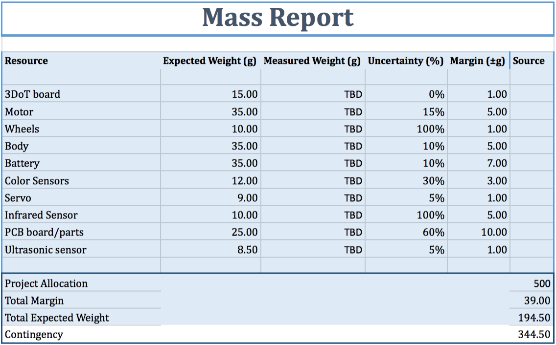
This report shows the mass of all the physical components used in the toy robot. There is quite a large amount of contingency because the rules of the maze has not been defined yet. Once those are defined, then the correct amount of sensors and components can be chosen.
Project Cost Estimate
By: Lucas Gutierrez (Project Manager)
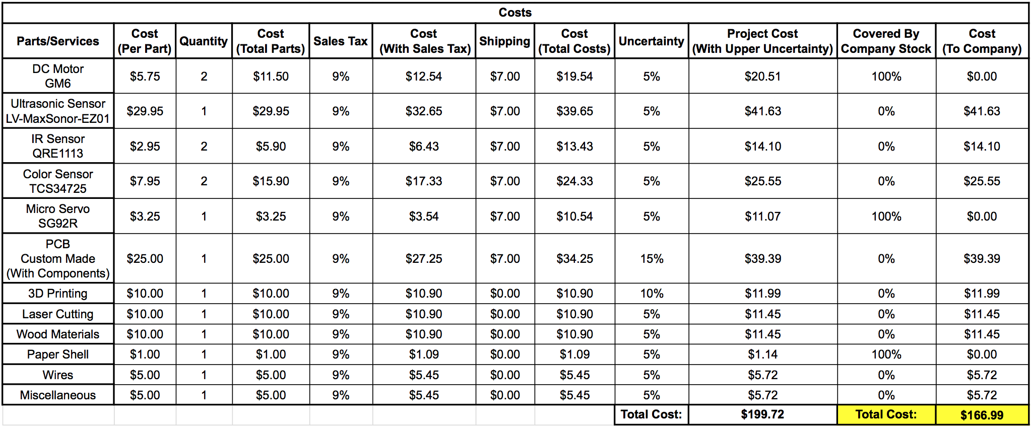
The cost report shows the current cost of components against the budget set by the customer. A larger pool of money was given towards the PCB board and components because of the uncertainty of certain sensors being required (maze rules). In case of laser cutting, money has been set aside to account for those costs.