Addressing Modes Part II: AVR Addressing Indirect
READING
The AVR Microcontroller and Embedded Systems using Assembly and C
by Muhammad Ali Mazidi, Sarmad Naimi, and Sepehr Naimi
Sections: 6.1, 6.3, 6.4
Table of Contents
ADDRESSING MODES
- When loading and storing data we have several ways to “address” the data.
- The AVR microcontroller supports addressing modes for access to the Program memory (Flash) and Data memory (SRAM, Register file, I/O Memory, and Extended I/O Memory).
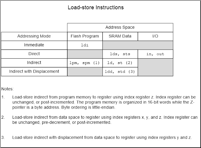
Figure 1: Load-Store Instructions Table
OPERAND LOCATIONS AND THE ATMEGA328P MEMORY MODEL
When selecting an addressing mode you should ask yourself where is the operand (data) located within the memory model of the AVR processor and when do I know its address (assembly time or at run time).
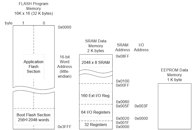
Figure 2: 8-bit AVR Instruction Set
Source: atmel.com
IMMEDIATE ADDRESSING MODE – A REVIEW
C++ Code
uint8_t foo; // 8-bit unsigned number, from 0 to 255
foo = 0x23;
Assembly Code
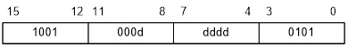
Data is encoded with the instruction. Operand is therefore located in Flash Program Memory. This is why technically our memory model is a Modified Harvard.
ldi r16, 0x23 // where ldi = 1110, Rd = 00002
// and constant K = 001000112
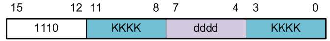
Figure 3: Encoded ldi Instruction
Notice that only four bits (dddd) are set aside for defining destination register Rd. This limits us to 24 = 16 registers. The designers of the AVR processor chose registers 16 to 31 to be these registers (i.e., 16 ≤ Rd ≤ 31).
What is the machine code instruction for our ldi example?
DIRECT ADDRESSING MODE – A REVIEW
C++ Code
uint8_t foo, A = 0x23; // 8-bit unsigned number, from 0 to 255
foo = A;
Assembly Code
.DSEG
A: .BYTE 1
.CSEG
lds r16, A
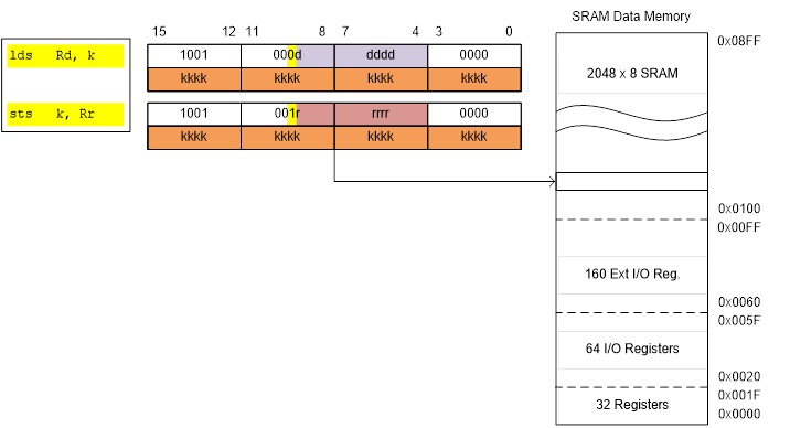
Figure 4: Encoded Instructions Using Direct Addressing
THE X-REGISTER, Y-REGISTER, AND Z-REGISTER
The registers R26..R31 have some added functions to their general purpose usage. These registers are 16-bit address pointers for indirect addressing of the data space. The three indirect address registers X, Y, and Z are defined as described here.
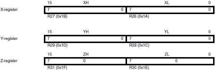
Figure 5: X, Y, and Z Registers Used for Indirect Addressing
In the different addressing modes these address registers have functions as fixed displacement, automatic increment, and automatic decrement (see the instruction set reference for details).
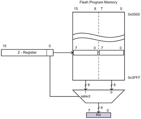
PROGRAM MEMORY INDIRECT
- The indirect addressing mode in all its forms is used when you will not know the location of the data you want until the program is running. For example, in our 7-segment decoder example, we do not know ahead of time which number (0 to F) we want to decode.
lpm Rd, Z
- Instruction Encoding
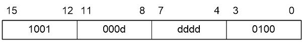
Figure 6: Encoded Instructions Using Indirect Addressing
TWO VIEWPOINTS
- You can look at the indirect addressing mode address as a word address with a byte selector (illustration on the left), or as a byte address (illustration on the right).
- The first viewpoint is correct from a computer engineering perspective (it is really how it is works). The second perspective is functionally equivalent and helps us visualize the computation of the indirect address as the sum of the base address plus an index.
- The most significant bit of the ZH:ZL is lost, to make space for the byte address in the least significant bit.
Addressing Mode Operation – Two Viewpoints
PROGRAM MEMORY INDIRECT WITH POST-INCREMENT
lpm r16, Z+
Instruction Encoding
Addressing Mode Operation
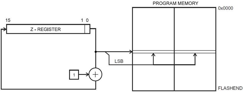
Figure 9: Indirect Addressing Diagram
PROGRAM MEMORY INDIRECT – EXAMPLE 1
ldi ZH, high(Table<<1) // Initialize Z-pointer (read next page)
ldi ZL, low(Table<<1)
lpm r16, Z // Load constant from Program
; Memory pointed to by Z (r31:r30)
…
Table:
.DW 0x063F // 0x3F is addressed when ZLSB = 0
// 0x06 is addressed when ZLSB = 1
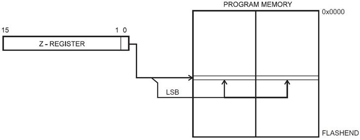
Figure 10: Indirect Addressing
PRINCETON VERSUS MODIFIED HARVARD MEMORY MODELS
Princeton or Von Neumann Memory Model
Program and data share the same memory space. Processors used in all personal computers, like the Pentium, implement a von Neumann architecture.
Harvard Memory Model
As we have learned in the Harvard Memory Model, program and data memory are separated. The AVR processors among others including the Intel 8051 use this memory model. One advantage of the Harvard architecture for microcontrollers is that program memory can be wider than data memory. This allows the processor to implement more instructions while still working with 8-bit data. For the AVR processor program memory is 16-bits wide while data memory is only 8-bits.
You may have already noticed that when you single step your program in the simulator of AVR Studio the Program Counter is incremented by 1 each time most instructions are executed. No surprise there right? Wrong. The program memory of the AVR processor can also be accessed at the byte level. In most cases this apparent paradox is transparent to the operation of your program with one important exception. That important exception is occurs when you want to access data stored in program memory. It is this ability of the AVR processor to access data stored in program memory that makes it a “Modified” Harvard Memory Model.
When you access from program memory you will be working with byte addresses not words (16-bits). The assembler is not smart enough to know the difference and so when you ask for an address in program memory it returns its word address. To convert this word address into a byte address you need to multiply it by 2. Problematically we do this by using the shift left syntax of C++ to explicitly tell the assembler to multiply the word address by 2. Remember, when you shift left one place you are effectively multiplying by 2.
With this in mind, we would interpret the following AVR instruction as telling the AVR assembler to convert the word address of label beehives in program memory to a byte address and then to take the low order of the resulting value and put into the source operand of the instruction.
ldi ZL,low(beeHives<<1) // load word address of beeHives look-up
PROGRAM MEMORY INDIRECT – EXAMPLE 2

Program Memory Indirect is great for implementing look-up tables located in Flash program memory – including decoders (gray code → binary, hex → seven segment, …)
In this example I build a 7-segment decoder in software.
BCD_to_7SEG:
ldi r16, 0b00001111 // limit to least significant
and r0, r16 // nibble (4 bits)
ldi ZL,low(table<<1) // load address of look-up
ldi ZH,high(table<<1)
clr r1
add ZL, r0
adc ZH, r1
lpm spi7SEG, Z
ret
//__________ gfedcba ___ gfedcba ___ gfedcba
table: .DB 0b00111111, 0b00000110, 0b01011011, …
// ________________0 _________ 1 _________ 2
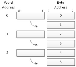
BIG ENDIAN VERSUS LITTLE ENDIAN – DEFINE BYTE
To help understand the difference between Big and Little Endian let’s take a closer look at how data is stored in Flash Program Memory. We will first look at the Define Byte (.DB) Assembly Directive and then at the Define Word (.DW) Assembly Directive.
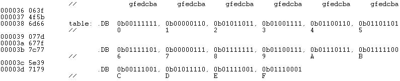
Figure 12: Bytes are First Stored in Lower Byte of the Address
Each table entry (.DB) contains one byte. If we look at the first table entry we see 0b00111111 which corresponds to 3f in hexadecimal. Comparing this with the corresponding address and data fields on the left… Wait a minute – where did 06 come from? That the second entry in the table (0b00000110 = 0616). The bytes are backwards and here is why.
There are two basic ways information can be saved in memory known as Big Endian and Little Endian. For Big Endian the most significant byte (big end) is saved in the lowest order byte; so 0x3f06 would be saved as bytes 0x3f and 0x06. For Little Endian the least significant byte (little end) is saved in the lowest order byte; so 0x3f06 is save as bytes 0x06 and 0x3f. As you hopefully have guessed by now the AVR processor is designed to work with data words saved as Little Endian.
BIG ENDIAN VERSUS LITTLE ENDIAN – DEFINE WORD
Now let’s take a closer look at how data is saved in program memory using the Define Word (.DW) Assembly Directive. For illustrative purposes we will look at a look-up table named beeHives.
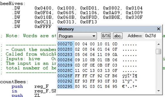
Figure 13: Memory Window Shows that the Word is Stored “Little Endian” (The Lower Byte) First
Each table entry (.DW) contains two bytes (1 16-bit word). These two bytes provide the row and column of a room containing bees. For example with respect to the maze, the room in row 00 column 04 contains 1 bee. If we look at the first entry we see it contains 0x0400. Comparing this with the corresponding Program Memory Window in AVR Studio… Wait a minute – that looks backward. From reading about the .DB assembly directive can you discover why?