Spring 2016: 3DoT Spider-Bot Cam Simulation
BY: Andrew Saprid ( manufacturing engineer)
Introduction
The initial design assumed that the CAM movement system would be used. Therefore, research on the CAM system and this CAM simulation were performed.
Requirements
Level 2 system requirement states:
- The 3DoT David shall use two micro motors for the movement system of the robot.
Table of Contents
CAM movement system model
All parts are assembled and connected with the top base and bottom base. The difficulties of making the CAM simulation included many mating in assembly that crashed the solidworks software many times. To prevent the solidworks software from crashing, mates may have to be suppressed so that resources may not be used as much in the software. A lot of parts will be 3d printed, and may exceed the 6 hour limit.

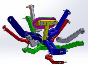
Here is the CAM and follower simulation of the 3Dot David model. By moving the CAM connected to the follower, three legs will move up, while the other three legs will move down:
Looking closely to simulate of the CAM movements system of the Hexbug Spider, steps are broken down to analyze and observe each part. The follower (yellow) is connected to the CAM (orange). By moving the follower, it will rotate just as the CAM rotates. The top femur (blue) is connected to the bottom femur (green). It’s support (red) will be connected to the bottom base. The bottom femur support (gray) will be connected to the top base.
 Hex bug design parts
Follower, CAM, and CAM cover
The follower (yellow) is connected to the CAM (orange). The CAM cover (purple) holds the CAM and follower in place.

Top femur
Top femur (blue) is connected to the joint(gray).

Joint
Joint (gray) is then connected to the bottom femur (green). This will make the joint free to rotate, and the top femur (blue) to go up and down.

Tibia
The tibias (gray) are then connected to the femurs.
Bottom Femur Support and Top Base
The bottom femur support (gray) is the connected to the top base (yellow).

Bottom Femur Support and Top Base
The bottom femur support (gray) is the connected to the top base (yellow).

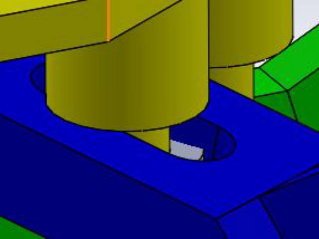
Slot bolt and the slot hole on the top femur
The slot bolt (gray) will restrict the top femur (blue) from going out. When moving the follower, the top femur will move, dependent on the slot hole.

Conclusion: CAM movement system model
All parts are assembled and connected with the top base and bottom base. The difficulties of making the CAM simulation, it included many mating in assembly that crashed the solidworks software many times. To prevent the solidworks software from crashing, mates may have to be suppressed so that resources may not be used as much in the software. A lot of parts will be 3d printed, and may exceed the 6 hour limit.