ScrewDriver
ScrewDriver Current draw and Battery Life
Author: Saba Theodory (Electronics and control)
Table of Contents
Introduction
The following experiments were conducted to measure the current draw for the prototype and the final robot and to calculate how long the battery will last in a worst case scenario. From these experiments, we determined that the onboard battery of the 3DoT board was enough to support the robot through the course and that no external battery is required.
Methodology
The current measurements we made in the following experiments were conducted as follows: The positive probe of the multimeter was connected to the positive rail while the negative probe was connected to the power pin of the load. The load is then grounded. The following image illustrates this process. In our case the lamp represents the load. Here is the link to the schematic used for building the prototype. The final uses the 3DoT board which is essentially the same control circuitry but with smaller motors.
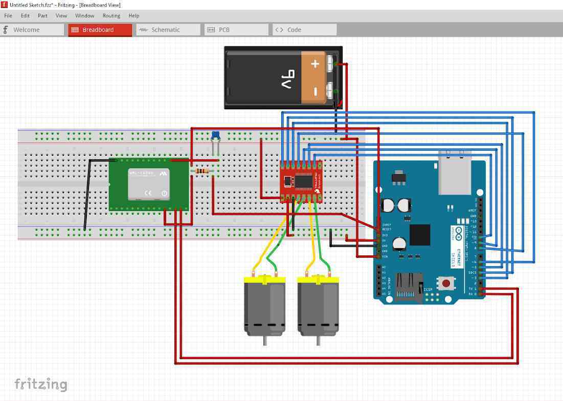
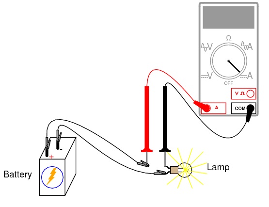
Figure 1: Current measurement methodology. Source: https://www.allaboutcircuits.com/textbook/experiments/chpt-2/ammeter-usage/
Rapid prototype tests
Before putting all the electronics together for the rapid prototype, a test of each component was made to have a good estimation of the total current draw of the system. Here is a table showing the measured current draw of those components.
| Component | Measured Current Drawn
(mA) |
| 9V DC motors No load (x2) | 188.4 |
| 9V DC motors with load (x2) | 368 |
| Arduino Leonardo | 32.4 |
| HM-11 Bluetooth module | 8.9 |
| TB6612FNG motor driver | 1.7 |
From this the total current drawn is around 411 mA. The picture below shows the current measured while the robot is idle meaning that the motors are off and only the control circuitry is on.
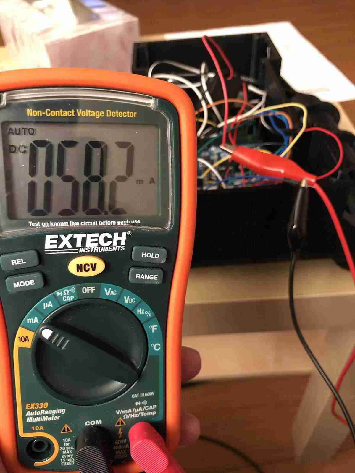
Figure 2: Current drawn in prototype when motors are off.
Another measurement that was made was the total current drawn when the motor speed was set to the slowest option. The image below shows that reading.
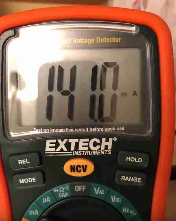
Figure 3: Current drawn in prototype when motors are at the slowest moving speed.
Final design tests
The current draw of the components was measured separately as shown in the table below:
| Component | Measured Current drawn (mA) |
| 6V DC motor x2 (No load) | 98.4 |
| 6V DC motor x2 (With Load) | 321 |
| 3DoT Board | 32.07 |
The multi-meter pictures are shown below.
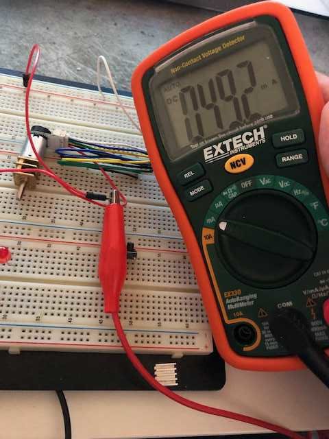
Figure 4: Current drawn by 6V DC motor at maximum speed.
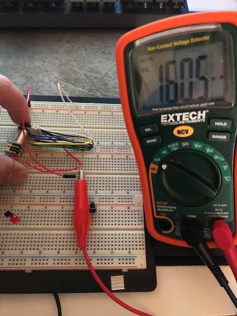
Figure 5: Current drawn by 6V DC motor with maximum speed and heavy load.
The load was placed on the motors by applying force to the shaft until it stopped rotating. This was to simulate the robot getting stuck on an obstacle. This process was done during short bursts however, since the motors might get damaged if this was done for a long period of time.
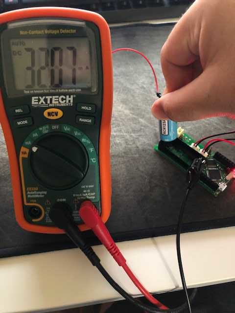
Figure 6: Current drawn by the 3DoT board.
The total measured current for the final robot is 353.07 mA. The battery we will be using is 650 mAh which will theoretically last us 1.84 hours before fully getting drained. The final robot uses the 3DoT board and the two metal gear motors as opposed to the prototype which uses larger 9V motors and has a much heavier chassis to carry around.
From these tests, we were able to compare the expected vs measured current draw. On the datasheet for the motors, the expected no load current draw is 60 mA and we got 49.2 mA which is fairly close. The rated current with load for these motors is 170 mA and our measurement was 160.5 mA.
Battery Life Calculation
Introduction
In this section, a calculation of the duration of the battery charge will be executed in order to confirm the longevity of the battery for the duration of the mission. The worst case scenario current draw will be used for this calculation in order to account for any unprecedented situations.
Power Allocation
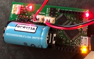
Figure 7: 3DoT board shown with the battery that will be used.
The power allocation selected for the final design of the robot is 650 mAh which is the onboard battery in the 3DoT board. The battery is a 3.6V RCR123A.
The total measured current draw for the system is 353.07 mA. This measurement is made assuming maximum current is drawn by both motors and the 3DoT board. From that we get 650 mAh/353.07 mA which will give us 1.84 hours of operation on a single charge assuming maximum current is drawn consistently.
Mission Duration
As shown here, the mission length is 66.64 m and as calculated here, the maximum speed is 0.1362 m/s. Using a simple calculation, the average time required to complete the mission is 489 seconds or 8.15 minutes. This means that we have a safety factor of 13.5x.
Conclusion
From these tests, we were able to view the actual current drawn from the battery by applying a heavy load to the motors and measuring the current rather than just relying on the manufacturer specifications. This process also helped in making sure everything was connected properly and there were no short circuits. This allowed us to determine that the 3DoT onboard battery is sufficient and no external battery will be required.