Introduction to AVR Assembly Language Programming II: ALU and SREG
READING
The AVR Microcontroller and Embedded Systems using Assembly and C
by Muhammad Ali Mazidi, Sarmad Naimi, and Sepehr Naimi
Sections: 2.4, 5.1, 5.2, 6.5
COMPLEMENTARY READING
The following source(s) cover the same material as Chapter 2 of your textbook.
They are provided to you in case you want a different viewpoint.
ATMEL document doc8161 “8-bit AVR Microcontroller with 4/8/16/32K Bytes In-System Programmable Flash” Section 6.3.1: SREG – AVR Status Register
Table of Contents
INSTRUCTION SET ARCHITECTURE (REVIEW)
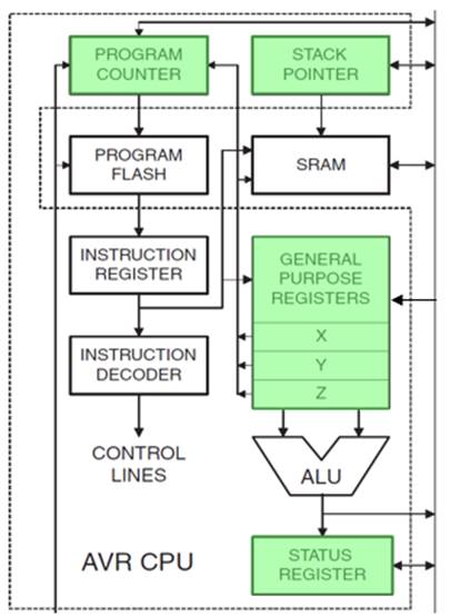
Figure 1: AVR Central Processing Unit ISA Registers
ALU – TWO OPERAND INSTRUCTIONS
- All math (+,-,×,÷) and logic (and, or, xor) instructions work with the Register File (register to register).
- Most math and logic instructions have two operands Rd, Rr with register Rd initially containing one of the values to be operated on and ultimately the result of the operation. The initial contents of Rd are therefore destroyed by this operation.
add Rd, Rr ; Rd = Rd + Rr, You may use any register (R0 – R31).
- Some math and logic operations replace the source register Rr with a constant K. Typically denoted by an “i” postfix.
subi Rd, K ; Rd = Rd – K, You may only registers (R16 – R31).
add, adc, adiw Adds two registers and the contents of the C Flag (adc only) and places the result in the destination register Rd.
sub, sbc, subi, sbci, sbiw Subtracts the source register Rs or constant K from the source/destination register Rr and subtracts with the C Flag (sbc and sbci only) and places the result in the source/destination register Rd. Think of the C Flag as the Borrow bit within this context.
mul, muls, mulsu, fmul, fmuls, fmulsu The multiplicand Rd and the multiplier Rr are two registers containing binary or fractional ( f-prefix) encoded numbers. Both numbers may be unsigned (mul, fmul), or signed (muls, fmuls). Finally, the multiplicand Rd may be signed with the multiplier Rr unsigned (mulsu, fmulsu). The 16-bit unsigned product is placed in R1 (high byte) and R0 (low byte).
and, andi, or, ori, eor Performs the logical AND, OR, and XOR operations between the contents of register Rd and register Rr or constant K.
ALU – SINGLE OPERAND INSTRUCTIONS
- All single operand math and logic instructions only need a single register and usually the mnemonic alone is enough to tell you what it does.
| Mnemonic | Operation | Description |
| com | One’s complement | |
| neg | Two’s complement | |
| inc | Increment | |
| dec | Decrement | |
| clr | Clear | |
| ser | Set Register, Limited to r16-r31 | |
| tst | Test for Zero or Minus |
ALU PROGRAM EXAMPLE
Write an Assembly program to implement the polynomial expression
B = A2 + A + 41
.INCLUDE
.DSEG
A: .BYTE 1 // 8 bit input
B: .BYTE 2 // 16 bit output
.CSEG
; load
lds r16, A ; r16 with the value of A
clr r17 ; r17 with 0
ldi r18, 41 ; r18 with 41
; do something
mul r16, r16 ; r1:r0 = A^2
add r0, r16
adc r1, r17 ; r1:r0 = A^2 + A
add r0, r18
adc r1, r17 ; r1:r0 = A^2 + A + 41
; store
sts B, r0 ; answer byte ordering
sts B+1, r1 ; is little endian
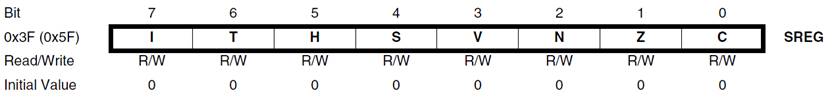
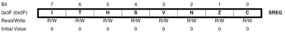
SREG – AVR STATUS REGISTER
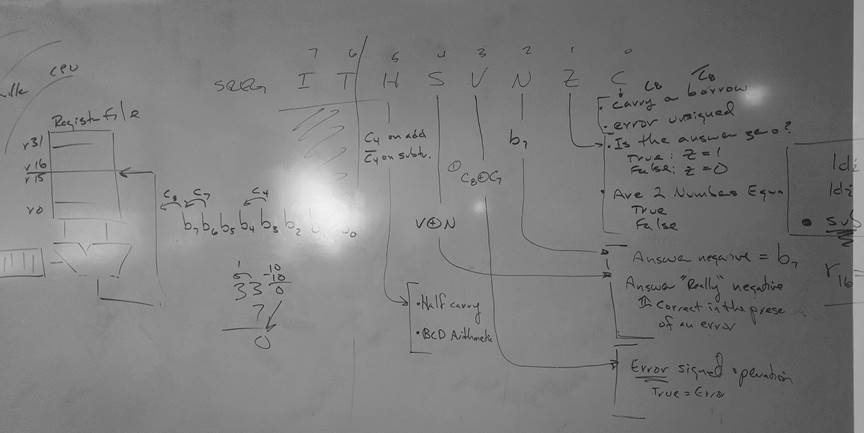
SREG – AVR Status Register
Non ALU
- Bit 7 – I: Global Interrupt Enable
The Global Interrupt Enable bit must be set for the interrupts to be enabled. The individual interrupt enable control is then performed in separate control registers. The I-bit is cleared by hardware after an interrupt has occurred, and is set by the reti instruction. The I-bit can also be set and cleared by the application with the sei and cli instructions. - Bit 6 – T: Bit Copy Storage
The Bit Copy instructions bld (Bit LoaD) and bst (Bit STore) use the T-bit as source or destination. A bit from a register can be copied into T (Rb -> T) by the bst instruction, and a bit in T can be copied into a bit in a register (T -> Rb) by the bld instruction.
ALU
Signed two’s complement arithmetic
- Bit 4 – S: Sign Bit, S = N ⊕ V
Bit set if answer is negative with no errors or if both numbers were negative and error occurred, zero otherwise. - Bit 3 – V: Two’s Complement Overflow Flag
Bit set if error occurred as the result of an arithmetic operation, zero otherwise. - Bit 2 – N: Negative Flag
Bit set if result is negative, zero otherwise.
Unsigned arithmetic
- Bit 5 – H: Half Carry Flag
Carry from least significant nibble to most significant nibble. Half Carry is useful in BCD arithmetic. - Bit 0 – C: Carry Flag
The Carry Flag C indicates a carry in an arithmetic operation. Bit set if error occurred as the result of an unsigned arithmetic operation, zero otherwise.
Arithmetic and Logical
- Bit 1 – Z: Zero Flag
The Zero Flag Z indicates a zero result in an arithmetic or logic operation.
THE SREG OVERFLOW BIT
- The overflow bit indicates if there was an error caused by the addition or two n-bit 2’s complement numbers, where the n-1 “sign bit” is 1 if the number is negative and 0 if the number is positive. In other words, the sum is outside the range 2n 1 to 2n 1 1.
- Another way to recognize an error in addition is to observe that if you add two numbers of the same sign (positive + positive = negative or negative + negative = positive) then an error has occurred.
- An overflow condition can never result from the addition of two n-bit numbers of opposite sign (positive _ negative or negative + positive).
- Here are examples of all four cases for two 8 bit signed numbers.
Case A B C D 0b6b5b4b3b2b1b0 0b6b5b4b3b2b1b0 1b6b5b4b3b2b1b0 1b6b5b4b3b2b1b0 0b6b5b4b3b2b1b0 1b6b5b4b3b2b1b0 0b6b5b4b3b2b1b0 1b6b5b4b3b2b1b0
The variable “bn” simply indicates some binary value and may be 1 or 0. The index of the carry bit (Cn) is equal to the carry into bit bn. For example, the carry into b0 is C0 and the carry out of an 8-bit register b7 is C8.
- Looking first at Case A, a carry cannot be generated out of the sign bit (Cn+1=0); therefore, if a carry enters the sign bit (Cn=1), the sum will be negative and the answer is wrong.
- For Case B and Case C no error can occur. Observe that in both case B and C because the numbers are contained in an n-bit (n = 8) register, we know they are in the range -2n-1 to 2n-1-1 (-128 to 127 for our two 8-bit numbers). Because one number is positive and the other negative, we further know, the answer must be correct.
- For Case D, a carry will always be generated out of the sign bit Cn+1=1 (ex. C8 = 1) with the sign bit itself set to 0; therefore, if a carry does not enter the sign bit Cn=0 (C7=1) the sum will be positive and the answer will be wrong.
- Here is what we have discovered translated into a truth-table.
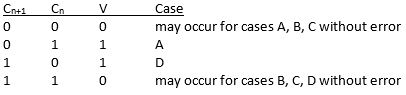
- Solving for the overflow bit (V) we have,
COMPUTING ALU STATUS REGISTER BITS – ADDITION –
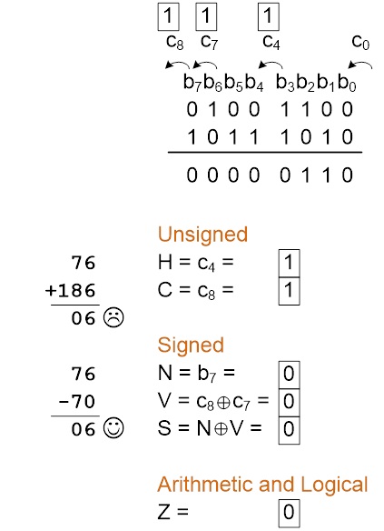
Figure 5: Signed vs Unsigned Addition
COMPUTING ALU STATUS REGISTER BITS – SUBTRACTION –
- For subtract instructions (sub, subi, sbc, sbci, sbiw), including compare instructions (cp, cpc, cpi, cpse), the carry bit is equal to
and
- Assume the subtract instruction sub r16, r17 has just been run by the ATmega328P microcontroller. Complete the table provided. The “difference” column should reflect the contents of register r16 after the subtraction operation (leave the answer in 2’s complement form) and not the actual difference (i.e., if done using your calculator).
Signed Unsigned r16 r17 difference relationship relationship H S V N Z C 3B 3B 00 + = + = 0 0 0 0 1 0 3B 15 26 + > + > 0 0 0 0 0 0 15 3B F9 F6 F6 F9 15 F6 F6 15 68 A5 A5 68 - Use AVR Studio simulation software to check your answers.