Goliath Fall 2016
Control Algorithm
By: Sou Thao (Electronics and Control)
Approved by Kristen Oduca (Project Manager)
Table of Contents
Introduction
Requirement: Goliath shall follow the Biped at a fixed distance of 20 inches with a margin of error of 15%.
In order to move Goliath autonomously, a control algorithm was created to enable Goliath to stay within the range of 20 inches from BiPed. The control algorithm takes the sensor’s data and controls the speed of the motors to allow Goliath to reach its set point at 20 inches away from an object. The control algorithm consists of a P, PI, or PID controller which helps to correct the error in reaching the object. The kp, ki, and kd constants represent the proportional, integral, and derivative constants respectively. In essence, the proportional constant helps to correct the error currently happening in the present. The integral term takes the information from the past and tries to correct the values so it can reach the set point sooner. The derivative term predicts what is going to occur in the future and correct the error and stabilizes it to reach the set point with less overshoot and a faster response time. For our case, we will be using a PI controller to automate Goliath’s movements.
Approach
Before we can write the control algorithm, we first have to see how we are going to automate the motors’ speed from the sensors’ values.
By drawing out the diagram of the sensor, we can see that the object is in the center between the two sensors. The distance from the left sensor to the object is da and the distance from the right sensor to the object is db. What we need to get is the distance from the object to the center between both sensors. This is shown in Figure 1.
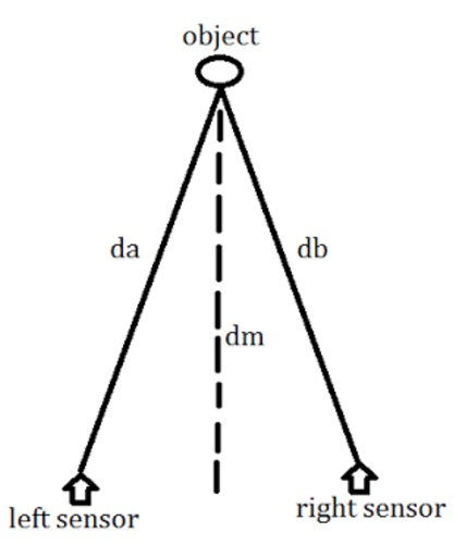
Figure 1 – Distance from Object to the Center of Both Sensors
In order to get this value, we take the error (da-db), divide it by 2, and add it to db. This would give us the mean distance dm which will be the distance from the object to the center of Goliath between both sensors. The error in the distance edist will be equal to the set distance minus the mean distance dm. For our set distance dT, we are using 20 inches because this gives us a good field of view for our camera to record BiPed. Thus, our control algorithm will work to correct the edist error so we can reach the set point at 20 inches or 50 cm.
To control the speed, the PI controller will take the error and change the speed of the motors to make the error zero. When da is greater than db, that means the object is to the left. When db is greater than da, that means the object is to the right. When both da and db are equal, the object is in the middle. Thus, we are able to control the speed of each motor by setting a minimum speed that each motor will have to run through and adding or subtracting the mean speed m to the minimum speed based on the direction the object is at. If the edist is less than the set point, then the motors will have to go in reverse. When going in reverse, the speed control is exactly the opposite as going forward. For example, when Goliath is going forward and moving left towards the object, the speed of the left motor is slower than the speed of the right motor. When going in reverse and the object is to the left, the left motor is moving faster than the right motor, therefore creating a left turn facing the object. This can be sown in the block diagram shown in Figure 2.
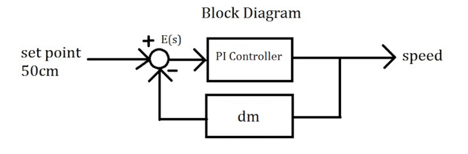
Figure 2 – Block Diagram
Steps to Writing an Algorithm
- Get the left sensor distance and store it under the variable da.
- Get the right sensor distance and store it under the variable db.
- Create a variable to store the error of (da-db)/2.
- Create a variable to store dm which is equal to the error plus db.
- Create a variable named edist to store values of the set distance minus dm.
- Create kp and ki constants to tune the PI controller.
- To find the proportional error, multiply kp by edist.
- To find the integral error, create an if statement that will accumulate all of the errors from edist before the setpoint of 50cm is reached.
- Next multiply the integral term by the ki constant to get the I in the PI controller.
- The mean speed will be equal to P+I.
- Create a minimum speed that each motor shall run on.
- If the object is to the right and its distance is farther than the 50cm, move the left motor by setting it to the minimum speed plus the mean speed. The right motor will be the minimum speed minus the mean speed.
- If the object is to the left and its distance is farther than the 50cm, control the speed of the motors opposite to step 12.
- If the object is in the middle and its distance is farther than the 50cm, control the speed of the motors by adding the mean speed to the minimum speed.
- If the object is to the left and its distance is less than the 50cm, change the speed of the left motor to the minimum speed plus the mean speed. The right motor will be the minimum speed minus the mean speed.
- If the object is to the right and its distance is less than the 50cm, the motors speed are opposite of step 15.
- If the object is in the middle and its distance is less than 50cm, control the speed of the motors the same as in step 14.
- If the object is 50cm away, stop both motors.
The Arduino C Code
int da,db;
float dm,m,edist,error, Integral;
int speedLeft,speedRight;
int dT = 50;
int minSpeed = 90;
Void loop() {
da = leftSensorAverage;
db = rightSensorAverage;
error = (da-db)/2;
dm = error+db;
edist = dT – dm;
int kp = 3;
int ki = 0.5;
int P = abs(kp*edist);
//stop the windup caused by the integral term
if (abs(edist)< 50){
Integral = Integral+edist;
}
else {
Integral = 0;
}
int I = abs(Integral*ki);
m = P+I;
if ((edist<0)&&(error>0)){
speedLeft = minSpeed + m;
speedRight = minSpeed – m;
}
else if ((edist<0)&&(error<0)) {
speedLeft = minSpeed – m;
speedRight = minSpeed + m;
}
else if ((edist<0)&&(error=0)) {
speedLeft = minSpeed + m;
speedRight = minSpeed + m;
}
else if ((edist>0)&&(error>0)) {
speedLeft = minSpeed – m;
speedRight = minSpeed +m;
}
else if ((edist>0)&&(error<0)) {
speedLeft = minSpeed + m;
speedRight = minSpeed – m;
}
else if ((edist>0)&&(error=0)) {
speedLeft = minSpeed + m;
speedRight = minSpeed + m;
}
else if (edist=0) {
speedLeft = 0;
speedRight = 0;
}
//set the limits to the speed so they
//do not go over 255 or under 0
if (speedLeft >255) {
speedLeft = 255;
}
else if (speedLeft < 0) {
speedLeft = 0;
}
if (speedRight >255) {
speedRight = 255;
}
else if (speedRight < 0) {
speedRight = 0;
}
}
Conclusion
The control algorithm was a useful tool in helping Goliath move autonomously. It was able to track an object very slowly, however, this can be fixed by adjusting the minimum speed, kp, and ki constants. We chose our minimum speed to be 90, our kp to be 3, and ki to be 0.5. It should be noted that we performed this control algorithm on the previous Goliath model meaning that these values will change because the new model is a different system. The new model’s constants will have to be fine tuned so they are able to track an object accurately. In conclusion, the control algorithm helped us in eliminating the jerking motion we previously encountered during our first prototype. We will be graphing the data from the sensors to see if the sensors are able to actually detect an object effectively, and we will be able to determine if a “bang-bang” system will be better to use than our current control algorithm.