Fall 2016 Velociraptor (W): Control Algorithm Code #2
By: Taylor Farr (Electronics and Controls)
Approved by:
– Lam Nguyen (Project Manager)
– Ryan Daly (Division Manager for Electronics and Control)
Table of Contents
Summary
The code for CDR utilizes IR sensors as rotary encoders. This was an okay method because it allowed for us to move the DC motors exactly 180 degrees. This is method could be improved with rotary encoders. We chose to use rotary potentiometers that can move a full rotation. Our PCB is powered by 3.3 volts, which means that the potentiometer value will vary between 0 and 3.3 volts. This is an analog signal, and our PCB only communicates via I2C.
[Link to A/D converter test]
We used the Adafruit ADS1015 to accomplish this. The test plan revealed that a span of 0-3.3 volts equates to a span of 0-1100 bits. This test proved flaws which improved the previous code, and allows for more precision in controlling the DC motors. This way, turning right and left will be more accurate. The option to move the motors at an angle of 90 degrees will keep the motors in place while the other leg moves continuously.
Code Description
The intent of the code is simple. Both legs will start off 180 degrees out of phase with the left leg forward and right leg in the back. The servo will move the head and tail to the left. The motors will both move 180 degrees to complete a step then stop. The head and tail will shift over the right leg. The motors will move 180 degrees again, then stop. The head and tail will shift to the left again. This completes the move forward subroutine.
Since the old encoders only move 180 degrees, turning would be impossible. The reason is that the legs cannot be moved to a position where all the center of mass can be placed on one leg without falling over. With the precision of the rotary encoder sensor, I can move the leg so that it is standing straight up. Once this movement is accomplished, the other leg will run continuously to turn. A similar process is used for turning the opposite direction.
Conclusion
Utilizing the rotary encoders and the I2C A/D converter allows for motors to be easily controlled. We can now position them with greater accuracy than the optical encoders. Figures 1 and 2 show the code used with comments.
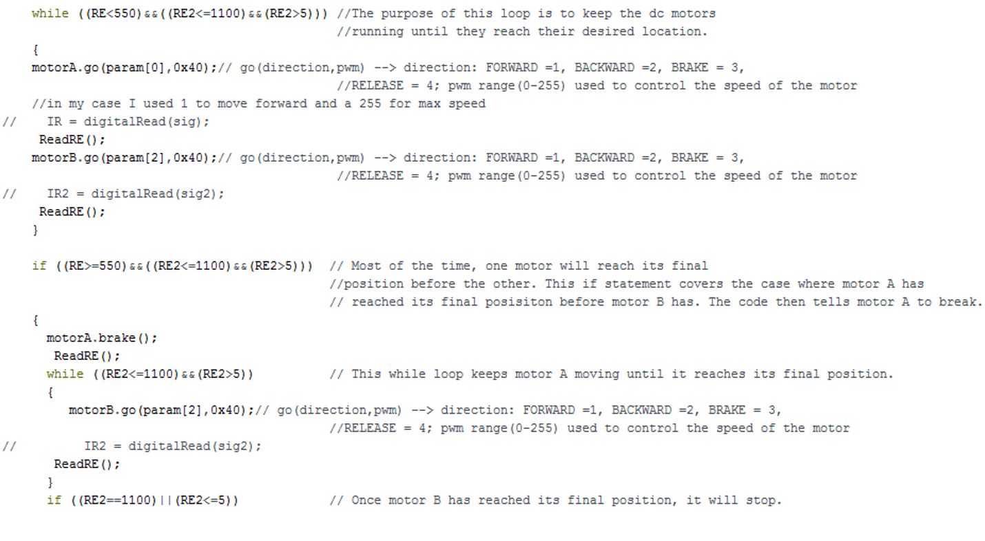
Figure 1: First part of the control algorithm
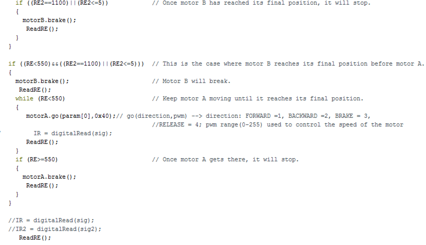
Figure 2: Second part of the control algorithm