Assembly Robot Lab 2 – Setting the motor speed and introduction to subroutines
Table of Contents
Introduction
This lab is focused on accurately controlling the speed of the motors in order to improve the maneuverability of the robot. The ideal result from this lab is that your robot should be able to move in a straight line without veering off of the path and having to correct itself. This will reduce the issues that you may run into once we start testing the robot with the physical maze. You will also learn more about subroutines and how we will be handling them in this course.
What Is New
The following instructions and assembly directives are introduced in Lab 2. If you have any questions on any instructions or assembly directives a nice source of information, in addition to your textbook, are AVR Instruction Set Manual and the Atmel AVR Assembler User Guide.
AVR Studio Assembly
Directives
.EQU Name1 Value1    // Tells the assembler to equate Name1 with Value 1 throughout the program
.DEF Name2 Name3     // Tells the assembler to use Name2 to replace Name3 (Name 2 is defined as Name3) throughout the program
Improving Control of the Motors
Up to this point, you have been simply turning the motors ON and OFF without regard to the speed. By default, the motors have been operating at full speed and you could have seen the robot veering to one side instead of going straight. This is not the best solution for navigating a maze and will require the development of an algorithm that will automatically correct the robot’s movement. In this lab, our main goal is to get better control our robot by addressing the possible mechanical issues like friction or component quality with adjustments to the speed of each motor. We will do this by using another subroutine that was included in robot3DoT.inc called AnalogWrite.
Creating Lab 2
To start, create a new project in AVR Studio 4.
- Give the lab an appropriate name and make sure the options to create the initial file and folder are selected.
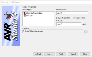
- Select AVR Simulator from the list of Debuggers and Atmega32U4 from the list of devices.
- Copy all of the code from the Lab1.asm file to the empty Lab_2.asm file.
- Copy the robot3DoT.inc file and upload.bat file from the Lab 1 folder to the Lab 2 folder.
- Assemble the code to make sure that it builds with zero errors and zero warnings.

How the AnalogWrite Subroutine Works
As mentioned in Prelab 2, the AnalogWrite subroutine is meant to be equivalent to the analogWrite() function used in the Arduino IDE. It is used to configure the speeds of each motor based on inputs provided by the user. The range of acceptable values used to represent the various speeds are from 0 to 255. While 255 corresponds to the fastest the motors can turn, 0 does not necessarily correspond to the motor moving at the lowest speed. It is more accurate to say that 0 would be equivalent to the motor being off and that there is a range of values where the motor is on but unable to turn. This is because those values represent the pulse width modulation duty cycle with 0 being 0% and 255 being 100%. It translates into a voltage being applied to the motors between 0 V and 5 V.
As this is a new subroutine, there are a few things to keep in mind. Unlike WriteToMotors, AnalogWrite requires two inputs and does not have any outputs. You will need to provide the two input values through registers 24 and 22 respectively. The values for each of these will have to be in hexadecimal. R24 is assigned to Motor A (left motor) and R22 is assigned to Motor B (right motor). If the values are not prepared properly before calling AnalogWrite, the subroutine will use whatever values were in those registers at the time and could result in unexpected results. That is why one of the rules for subroutines is to always load the arguments before calling the subroutine. More information about these rules that have not been covered so far are listed in Appendix A.
With this information, we can move onto the main focus of Lab 2.
Find the Maximum Speed
There is a high probability that your two motors are not equal. This is typically due to a difference in the internal friction of the gears and motors, which translates into a difference in the speed of rotation at a given voltage or duty cycle. This will cause your robot to veer towards the right or left. In order to address this issue, we will be start by finding the ideal maximum speed for the fastest motor such that the robot travels in a straight line (or at least as close as possible).
This portion of the lab involves a lot of trial and error. We will be placing the robot on the printed maze and verifying if it is moving in a straight line. If it reaches the room boundary without moving towards a side wall, then you have found the appropriate speed on each motor. If not, try changing the speed of one of the motors and check the result. You will be manually controlling the speed of each motor using the AnalogWrite subroutine. Add the following lines of code to the main loop.
...Previous Code...
     ldi r24, 0x05
     call WriteToMotors

     ldi r24, 0xFF     // value for speed of Motor A, left motor
     ldi r22, 0xFF     // value for speed of Motor B, right motor
     call AnalogWrite  // sets speed of both motors using inputs r24 and r22.

     rjmp loop
Begin with both motors running at full speed (PWM value of 255) and record in which direction the robot drifts towards. If it drifts to the right, then the left motor is faster than the right. Decrease the speed of the faster motor by lowering the duty cycle (PWM) of the faster motor. Repeat this process until the motors are in sync. Define the maximum speed for both motors as RightHIGH and LeftHIGH respectively with the following assembly directives. Make sure these directives are added before RST_VECT and after .INCLUDE < m32u4def.inc >.
.EQU RightHIGH = 0x____ (Fill in with the value that you determined. It should be between 0 and 255).
.EQU LeftHIGH = 0x____
With this, you will be able to use the terms RightHIGH and LeftHIGH instead of values that were determined in the exercise. For example, ldi r24, 0xFF would become ldi r24, LeftHIGH.
Find the Minimum Speed
Now that you have found the maximum speed, the next step is to find the minimum speed that will keep the motors synchronized and provide a safe margin above the stall speed for both. A motor will stall when there is insufficient power to the motor to overcome the internal friction of the gears and motor (i.e., nothing is moving). The motor is ON at this point and it is consuming power but there is no physical motion. This may damage the motor and should be avoided. By obtaining the minimum speed to get the motor moving, we can keep the motor ON and barely moving while the robot smoothly gets back on track. Make sure to find a speed that has the wheel moving at a reasonable pace. We do not need it to be barely moving but it should be distinguishable from the maximum speed. Feel free to go about 10 or 15 more than the lowest value that satisfies these conditions.
Using trial-and-error, determine the minimum speed for each motor. Specifically, slowly decrease the duty cycle (PWM value) until the minimum speed is reached with a margin of safety. If you pick a value where the motors are not turning, turn off the robot immediately to prevent damage. This should never happen as the AnalogWrite subroutine will default to a value of 0x50 if anything lower is inputted. If it seems like the value could go lower than 0x50 for your motors, please inform your lab instructor.
Next, run both motors at their minimum speed and note how the robot deviates from the line. Increase the speed of the slower motor. Repeat this process until the motors are in sync. We are not looking for just the minimum speed of each motor but the minimum speed for both to still move in a straight line. Define the minimum speed for both motors as RightLOW and LeftLOW. If you have the time and want your robot to move through the maze in a reasonable amount of time, the motors should be set to a value in between the maximum and minimum that is able to move in a straight line. This is optional as the minimum speed is enough to make it through the maze.
Once you have defined all of these values, Lab 2 is complete.
Lab 2 Deliverable(s)
|
All labs should represent your own work – DO NOT COPY. Submit your list file as defined below. Make sure that the code compiles without any errors. Do not forget to comment your code. Lab 2 Demonstration
|
Appendix A: Rules for Working with Subroutines
In the last lab I introduced three steps for writing a program for a load-store RISC based architecture.
- Load the data (lds),
- Do something (typically an arithmetic or logical instruction), and then…
- Store (sts) the result.
When working with subroutines an analogous set of steps applies.
- Load argument(s) into input registers (parameters) specified in the header of the subroutine. Following the gcc C++ calling convention, this would be register r24 if only one calling argument is specified (lds r24, myData).
- Call the Subroutine
- Do something with the return value(s) stored in the output register(s) specified in the header of the subroutine. Following the gcc C++ calling convention, this would be register r24 if a single byte value is returned. In most cases you will storing this return value(s) into SRAM data memory (sts myData, r24).
You call a subroutine using the rcall or call assembly instruction and return using the ret instruction. Here are a few rules to remember when writing your main program and subroutines.
- Your subroutine should always include a header block. As a minimum, the header must define the input arguments to the subroutine, the values returned, and what if any registers are modified by the subroutine.
- Always initialize variables and registers at the beginning of your program. Do not re-initialize variables or registers within a loop or a subroutine. For example, you only need to configure the port pins assigned to the switches once.
- Never jump into a subroutine. Use a call instruction to start executing code at the beginning of the subroutine.
- Never jump out of a subroutine. Your subroutine should contain a single return (ret) instruction as the last instruction.
- You do not need an ORG assembly directive. As long as the previous code segment ends correctly (rjmp loop, ret, reti) your subroutine can start at the next address.
- Subroutine names start with a capital letter.
- Your subroutine should contain only one return instruction (ret, reti) located at the end of the subroutine (last instruction). All blocks of code within the subroutine should exit the subroutine through this return (ret).
- Push (push r7) any registers modified by the subroutine at the beginning of the subroutine and pop (pop r7) in reverse order the registers at the end of the subroutine. This rule does not apply if you are using one of the registers or SREG flags to return a value to the calling program. Comments should clearly identify which registers are modified by the subroutine.
- You cannot save the Status Register SREG directly onto the stack. Instead, first push one of the 32 registers on the stack and then save SREG in this register. Reverse the sequence at the end of the subroutine.
push r15
 in r15, SREG
 :
 out SREG, r15
 pop r15
- Once again, never jump into or out of a subroutine from the main program or any other subroutine. However, subroutines may call other subroutines.