AT-ST/Fall/2018
AT-ST Fall ’18: Flow chart – Shaft Encoders and Motor Phase PID
Author/s: Brian Ababat
Table of Contents
Introduction
Two DC motors are used to move the legs of the AT-ST walker. In order for the walker to move properly, the motors must remain 180 degrees out of phase. In order to achieve this, shaft encoders in conjunction with a PID control system are used. Details of how a PID controller works can be found here.
Shaft Encoders
Shaft encoders convert the angular position of a rotating device into an electrical signal. As the shaft rotates, the encoder generates two square waves. The frequency of the square waves can then be used to determine the RPM of the motor and the square wave that pulses first determines which direction the shaft is rotating.
The motor we use comes with a shaft encoder. Below is the pin diagram of the motor.
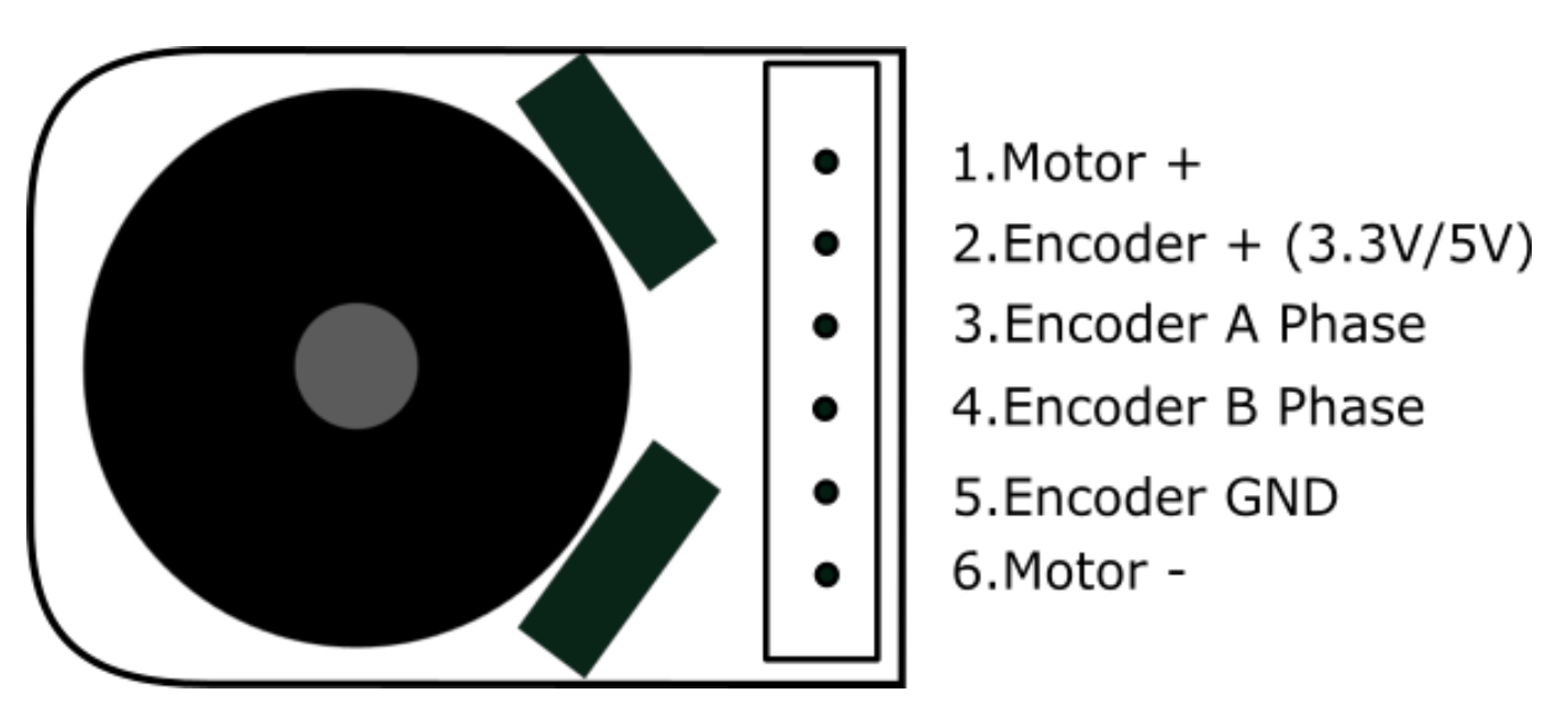
Figure 1: Pin Diagram
Encoder A phase and encoder B phase are the two pulses mentioned above. The Teensyduino Encoder library was used to detect the number of pulses sent by a motor. Using the read() command, a value up to 4200 counts can be read. This value was obtained by looking at the hall feedback resolution of the encoder and discovering that a count of 2100 yielded half a rotation.
Further examination of the shaft encoder was performed using an optical sensor in a fixed position. A gear with a marked, reflective surface was attached to the motor. The optical sensor would send a signal to the Arduino after the motor completed one full rotation. This would prompt the Arduino to print out and then reset the encoder count. Using this method, it was found that an average value of 4220 would indicate one full rotation.
The shaft encoders are used to determine the phase (angular position) and RPM (angular velocity) of the DC motors. To determine the phase of a motor, the encoder’s current count is compared to the maximum count of 4220. For example, a phase of 180° would mean the encoder’s current count would be 2110. To determine the RPM, the encoders are periodically polled to compare the current counts with the previous counts. To extrapolate the RPM, the difference between these two counts are multiplied by 6000 (as there are 60000 milliseconds in one minute) and then divided by the maximum count.
PID Feedback
The requirements of the AT-ST are as follows:
- The RPM of the two DC motors must be kept equal and consistent.
- The phase of the second DC motor must be kept 180° out of phase of the first DC motor.
From these conditions, it was decided that two PID controllers must be used. The first PID controller would monitor the RPM of motor 1 and keep the RPM at the desired value. The second PID controller would monitor the phase of motors 1 and 2 and maintain a phase difference of 180°, thereby also maintaining the desired RPM.
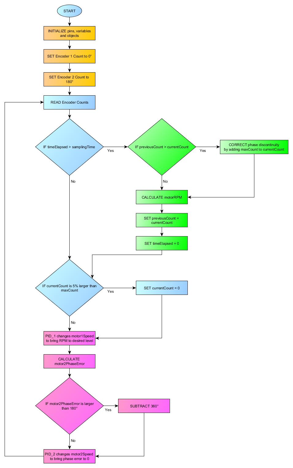
Figure 2: Flowchart of motor control. Setup (Orange). RPM Calculations (Green). PID Control (Purple).
PID control requires an input signal that is observed, a setpoint which is defined as the value the controller tries to bring the input to, and an output that affects the input.
The first PID controller controls motor 1. The input of the controller is the RPM of motor 1 which is calculated using the method detailed in the shaft encoder section above. The setpoint of the controller is our desired RPM of 52.5. The output of the controller is the PWM value for motor 1.
The second PID controller controls motor 2. The input of this controller is the phase error of motor 2. The phase error is determined as:
The phase error is how far the phase of motor 2 is from being 180° out of phase with motor 1. The desired behavior of our motor is:
- If motor 2 is ahead of the target position, the motor slows down.
- If motor 2 is behind the target position, the motor speeds up.
The easiest way to achieve this is to limit the phase error to ±180°. This is done by checking if the phase error is larger than 180°, and if so to subtract by 360°. The setpoint of the controller is 0 because we desire motor 2 to remain 180° out of phase. The output of the controller is the PWM value for motor 2.
Arduino Code
#include
#include
#include
#include

// Pin declarations
const int encoder1A = 3;
const int encoder1B = 10; // Interrupt pin 2
const int encoder2A = 2;
const int encoder2B = 9; // Interrupt pin 1

const int opticalSensor1 = 12;
bool os1State = false;
const int opticalSensor2 = A0;
bool os2State = false;

// Define the Adafruit Motorshield objects
Adafruit_MotorShield AFMS = Adafruit_MotorShield();
Adafruit_DCMotor *motor1 = AFMS.getMotor(1);
Adafruit_DCMotor *motor2 = AFMS.getMotor(4);

// Define the Encoder objects
Encoder encoder1(encoder1A, encoder1B);
Encoder encoder2(encoder2A, encoder2B);
const int maxCount = 4220;

// Define the timeElapsed variable. Used for RPM calculation
elapsedMillis timeElapsed = 0;

unsigned long int milliTime;


// Motor Characteristics
int motor1Count, motor2Count; // Encoder counts. There are an estimated 4200 counts per rotation
double motor1RPM, motor1Phase, motor2RPM, motor2Phase; // RPM and phase variables used for PID control
double motor1Speed; // Speed for motor 1 and base speed for motor 2

// RPM PID Variables
int lastCount1, lastCount2, samplingTime; // lastCount is the encoder count since the last sample
double motor1DesiredRPM = 30.0; // The RPM we want to be running at
double conversionFactor; // The constant conversion factor. Converts the percent rotation of the sample time into an estimated RPM count
PID pidMotor1Speed(&motor1RPM, &motor1Speed, &motor1DesiredRPM, 0.5, 1.0, 0.0, DIRECT); // PID pidObject(&Input, &Output, &Setpoint, Kp, Ki, Kd, Direction)

// Phase PID Variables
double motor2PhaseError, motor2Setpoint, motor2Speed; // (PhaseError) is how far the motor is from (Setpoint). (SpeedAdjustment) is the change in PWM value to compensate
PID pidMotor2Speed(&motor2PhaseError, &motor2Speed, &motor2Setpoint, 0.080, 0.8, 0.0, REVERSE); // PID pidObject(&Input, &Output, &Setpoint, Kp, Ki, Kd, Direction)

void setup()
{
  Serial.begin(9600);

  // LOGGING
  Serial.println("CLEARDATA");
  Serial.println("LABEL,Computer Time,Arduino Time,Motor 1 Count,Motor 2 Count,Motor 1 Speed,Motor 2 Speed,Motor 1 RPM,Motor 2 RPM");

  ///////////////////////
  // Motorshield Setup //
  ///////////////////////
  AFMS.begin();
  motor1->setSpeed(motor1Speed);
  motor2->setSpeed(motor1Speed);


  ///////////////////
  // Encoder Setup //
  ///////////////////
  // Sets encoder counts to 0
  motor1Count = 0;
  motor2Count = maxCount/2;

  // Motor 1 begins at a phase of 0 degrees.
  encoder1.write(0);

  // Motor 2 begins out of phase
  encoder2.write(maxCount/2);


  /////////////////////////////////
  // Setup relating to motor1PID //
  /////////////////////////////////
  // RPM Calculation
  lastCount1 = 0;
  lastCount2 = maxCount/2;
  samplingTime = 100;

  // Define a constant that takes into account the conversion of units for RPM calculation
  conversionFactor = 60.0 * 1000.0 / maxCount; // (60 seconds * 1000 milliseconds / 4200 counts for 1 full rotation)

  // Controls motor1Speed
  motor1Speed = 0;
  pidMotor1Speed.SetMode(AUTOMATIC);


  /////////////////////////////////
  // Setup relating to motor2PID //
  /////////////////////////////////
  // Controls motor2SpeedAdjustment. Need to go up or down.
  motor2Setpoint = 0;
  pidMotor2Speed.SetMode(AUTOMATIC);
  //pidMotor2Speed.SetOutputLimits(-126, 126);


  ////////////////////////////////////////
  // Setup for the Pin Change Interrupt //
  ////////////////////////////////////////
  pinMode(opticalSensor1, INPUT);
  digitalWrite(opticalSensor1, HIGH);
  pciSetup(opticalSensor1);

  pinMode(opticalSensor2, INPUT);
  digitalWrite(opticalSensor2, HIGH);
  pciSetup(opticalSensor2);
}

void pciSetup(byte pin)
{
  *digitalPinToPCMSK(pin) |= bit (digitalPinToPCMSKbit(pin));  // enable pin
  PCIFR |= bit (digitalPinToPCICRbit(pin)); // clear any outstanding interrupt
  PCICR |= bit (digitalPinToPCICRbit(pin)); // enable interrupt for the group
}


ISR(PCINT0_vect) // Pin change interrupt for D8 to D13
{
  // Change when pin opticalSensor1 goes LOW
  os1State = !os1State;
  if(os1State){
    encoder1.write(0);
  }
}

ISR(PCINT1_vect) // Pin change interrupt for A0 to A5
{
  // Change when pin opticalSensor2 goes LOW
  os2State = !os2State;
  if(os2State){
    encoder2.write(0);
  }
}

void loop()
{
  /////////////////////////////////
  //  Calculating Phase and RPM  //
  /////////////////////////////////
  motor1Count = encoder1.read();
  motor2Count = encoder2.read();
  milliTime = millis();

  // Calculate RPM when we reach polling for motor 1 and 2
  if(timeElapsed > samplingTime){

    if(lastCount1 > motor1Count){
      motor1RPM = (motor1Count + maxCount - lastCount1) * ((conversionFactor/timeElapsed));
    } else {
      motor1RPM = (motor1Count - lastCount1) * ((conversionFactor/timeElapsed));
    }
    if(lastCount2 > motor2Count){
      motor2RPM = (motor2Count + maxCount - lastCount2) * ((conversionFactor/timeElapsed));
    } else {
      motor2RPM = (motor2Count - lastCount2) * ((conversionFactor/timeElapsed));
    }

    lastCount1 = motor1Count;
    lastCount2 = motor2Count;
    timeElapsed = 0;
  }

  // Reset count and calculate RPM when we go 5% over the expected count for motors 1 or 2
  if(motor1Count > maxCount + (maxCount * 0.05) ){
    encoder1.write(0);
  }
  if(motor2Count > maxCount + (maxCount * 0.05) ){
    encoder2.write(0);
  }

  //////////////////////////////////
  //  Calculating speed using PID //
  //////////////////////////////////
  // Calculate the setpoint for pidMotor2Speed
  motor2PhaseError = motor1Count + maxCount/2 - motor2Count;
  if(motor2PhaseError > maxCount/2){
    motor2PhaseError -= maxCount;
  }

  pidMotor1Speed.Compute();
  motor1->setSpeed((int) (motor1Speed));

  pidMotor2Speed.Compute();
  motor2->setSpeed((int) (motor2Speed));

  //////////////////////////
  //  Running the motors  //
  //////////////////////////
  motor1->run(FORWARD);
  motor2->run(FORWARD);


  /////////////////////////
  //  Plotting Feedback  //
  /////////////////////////
  Serial.print("DATA,TIME,");
  Serial.print(milliTime);
  Serial.print(",");
  Serial.print(motor1Count);
  Serial.print(",");
  Serial.print(motor2Count);
  Serial.print(",");
  Serial.print(motor1Speed);
  Serial.print(",");
  Serial.print(motor2Speed);
  Serial.print(",");
  Serial.print(motor1RPM);
  Serial.print(",");
  Serial.println(motor2RPM);
}
Four libraries are used in this code.
Encoder.h is the library used to read the encoders attached to the motors. This library is used to detect the encoder’s pulses and create the count values that is the basis of our feedback system. Since the Arduino Uno is limited to two external interrupt pins, we are limited to using one external interrupt pin and one regular pin for each encoder. In comparison, the ideal connection would be to use two external interrupt pins for each encoder. To use this library, an Encoder object has to defined with the two pins connected to the physical encoder. This object has two methods, both of which are used. Read() returns the accumulated count, which the Encoder object stores. Write(int newCount) sets the internal count to the newCount value. This method is used to reset the count to 0 every time the motor completes one full rotation.
Adafruit_MotorShield.h is the library used to interface with the Adafruit Motorshield v2 which is used to drive the two motors. To use this library, an Adafruit_MotorShield object has to be created. Afterwards, an Adafruit_DCMotor object is created for each DC motor. We use two methods to control the physical DC motors. setSpeed(int newSpeed) sets the PWM value for the DC motor which sets the speed of a DC motor. run(DIRECTION) causes the motor to be run. DIRECTION can be one of three values. FORWARD causes the motor to be run in one direction, BACKWARD causes the motor to be run in the opposite direction, and RELEASE causes the motor to stop running.
(Note that since this library makes you define a pointer for the Adafruit_DCMotor object, as indicated by the *, we must use the arrow operator rather than the dot operator for calling methods)
PID_v1.h is the library used to create a PID control system. To use this library, a PID object has to be created. An in-depth explanation of this library and its constructor can be found here. We use two methods from this library. SetMode() is used to turn on the PID controller. Compute() is used to adjust the output variable automatically, in this case it is used to vary the motor PWM values.
elapsedMillis.h is the library used to create for polling our encoders. To use this library, a variable is defined as elapsedMillis. This variable will automatically increase and no methods need to be used.
Two pin change interrupts are used for two optical sensors. These optical sensors are used to detect when the motor completes one full rotation. A gear is attached to each motor shaft. A gear is attached to the motor shaft. When the motor finishes one full rotation, the optical sensor detects a strip of a reflective surface. The pin change interrupt detects the voltage level going from HIGH to LOW then back to HIGH. Since we only care about the change from HIGH to LOW, we change the encoder count when the pin reads LOW. These sensors are necessary because the shaft encoders measure a relative value. If we only set the phase to 0 when the encoder count exceeded 4220, drift would likely occur.
In the case that the optical sensor did not pick up the reflective sensor and the encoder count were to continue to increase, an IF statement was included to set the encoder count back to 0 if it exceeded the maximum count by 5%.
Measurement Methods
To observe the effects of the PID controller in real-time, two methods can be used.
The first method can be performed with no additional setup. The Arduino IDE comes equipped with a serial plotter that can be used to plot any variable with a number value associated with it. To use the serial plotter, replace the code in the Plotting Feedback section with the following:
//Plots the phase and speeds
Serial.print(motor1Count/21);
Serial.print(",");
Serial.print(motor2Count/21);
Serial.print(",");
Serial.print(motor1RPM);
Serial.print(",");
Serial.println(motor2RPM);
This code can be changed to plot any other values. To use the serial plotter properly, the variables plotted have to be separated by a comma. The last variable that is to be plotted is then printed using println. The expected range of values for the encoder counts is from 0 to 4220. The range of values for the RPM value is from 0 to 70. Thus, the encoder counts is divided by an arbitrarily decided value of 21 to keep the range of values close to each other.
Shortcomings of the serial plotter is that it is difficult to obtain usable information from. There are no methods to pause the plot and observe the effects, or any method for reviewing the data points. As such this method is suitable for determining whether the general trends of the code is operating properly. This would be useful for finding whether the RPM of both motors are the same and remaining constant.
The second method uses an Excel macro produced by Parallax to both record and plot the data. This macro is called PLX-DAQ and can be downloaded here. The code above is already formatted to use this macro. To use this macro, code is included under the LOGGING portion of the setup code. CLEARDATA is printed to clear any Excel data currently being recorded. The next line sets up the various column titles. The data is then sent in much the same way as the serial plotter. Under the Plotting Feedback section, code is sent using Serial.print() and Serial.println(). The only difference is that it is necessary to start the string with “DATA” to tell the macro to start recording data. “TIME” is used to tell the macro to record the computer’s internal clock. After the Arduino code is formatted properly, the PLX-DAQ macro has to be opened. Once the correct port and baud rate are selected, data can be logged by clicking on the Connect button of the macro.
Results
Using the PLX-DAQ macro the motor phases, motor RPMs, and motor PWM values were recorded and then plotted using Excel. The rise time, settling time, and other control measurements can be found by exporting the results as a comma separated values file (.csv) and then analyzed using MATLAB if necessary or desired.
The result of one test is shown below in Figure 3. There is a transient period of around 10 seconds before both PIDs reach their desired values. During the transient state, the phase for motors 1 and 2 will drop to 0 before they reach the expected count of 4220 and and cause the RPM calculations to spike. This is because we start with the assumption that the motors start a 0° and 180° respectively. As the motors rotate, they trigger the optical sensors and correct the starting assumption. This behavior cannot be avoided with the current setup.
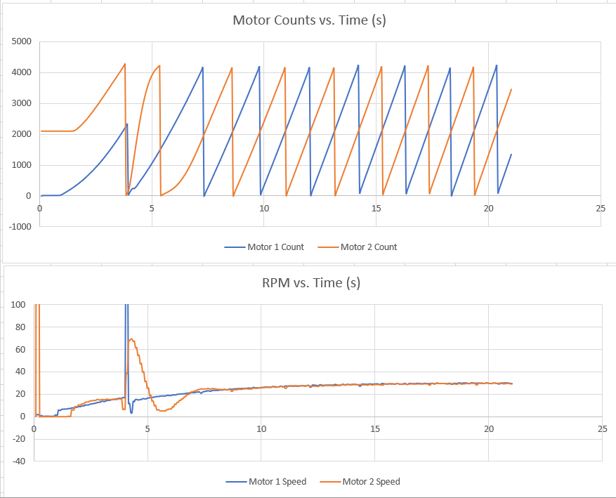
Figure 3: Motor Phase and RPM plots.
These results show that the two PIDs are fulfilling the two requirements properly. Introducing a load (by way of placing a finger on the gear), causes the RPM to decrease temporarily before the PWM value is adjusted and the motor RPM is brought back to the desired value. Figure 3 shows an old result where the desired RPM was set at 30.
The raw data can be downloaded here as a .csv file.
Required Libraries
Conclusion
Two PID controllers are capable of fulfilling the two requirements. There will be a brief transient period when the PIDs are started. Further work can still be made into analyzing the rise time, settling time, and overshoot and determining whether the current PID constants achieve what we desire.