Sojourner Spring 2020
Back EMF Initial Study
Author: Robert Pearson
Verification: Robert Pearson
Approval: Chris Hirunthanakorn
Table of Contents
Background
What is Back EMF?
Editor: This post includes a number of errors. Please see an alternative post by David Garcia on the same subject.
When a motor spins, the coil inside produces a magnetic field. This magnetic field, in turn, creates a voltage, known as an Electromotive Force. The intensity and peak of Back EMF is speed-dependent, the higher the speed the greater the Back EMF. An electromotive force, or EMF, opposes the voltage that is applied to the motor which can reduce the overall current passing through the motor.
For our project, Back EMF can be a viable method of sensorless rpm, as we can measure the voltage generated by the motor. Through experimentation, the measured Back EMF can be relayed into a digital value for the range of the Polulu DC motor we are using. Knowing the intended digital value we should be able to use that to create firmware where it can adjust the speed to the user’s intended settings, creating a more accurate and responsive robot.
Back EMF for Encoding
The two methods for sensorless rpm that we initially considered are back emf and commutator noise. The commutator noise research blog post can be found here.
The back emf method utilizes our motor as a generator to send a voltage to an ADC. A crucial part of using back emf is to allow for a sufficient latency period between the shutoff of the motor and data collection. Two notions to consider for back emf sensorless encoding are that: it can only be used for velocity unlike encoders, which could be used for the position as well and that it will only work for brushed DC motors, not brushless DC motors.
The back emf makes use of the motor as a generator when the PWM signal is low. We measure the voltage produced by the motor during this time, this value is the back emf. The back emf is proportional to the speed of the motor. When we increase the voltage or duty cycle of the PWM signal, the back emf value increases as well. Through testing, we can calculate Kp to divide our back emf by to determine the rpm of the motor.
A possible solution to measuring the back EMF, according to Precision Microdrives, would be putting a resistor in series to the motor which will, in turn, create thermal noise, and let the Voltage through the circuit vary.
Circuit Design
While testing the Back EMF circuit, we used the schematic provided by Precision Microdrives in order to try to measure the Voltage Spikes. The Precision MicroDrives Circuit was decided on due to the availability of the components described in their schematic.
When looking for Back EMF spikes of a motor, information on RPM data can be relayed by the number of voltage spikes per cycle. According to the circuit by Precision MicroDrives the number of spikes seen are double the amount of sectors in the commutator. For example, a four pole motor will see 8 voltage spikes per one full rotation.

Figure 1 – Precision MicroDrive’s Back EMF Test Circuit
The Capacitor values weren’t given in the schematic so through trial and error, we ended up using 100uF for C1 and 100uF C2, below are our results.
Initial Testing
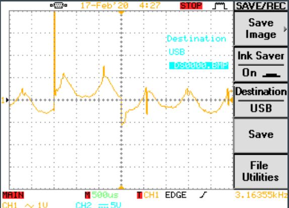
Figure 2 – Scope Outputs
The spikes were seen at a value of a peak value of 4.3 V when running the motor at full power, although for further testing we have to consider how the fly back diode in our motor driver could possibly reduce this spike, as the noise level would be brought down. This result could leave this method not viable for our project.
Motor Driver
When testing the motor initially, it was in a circuit with power directly connected to a voltage supply. This test could not be deemed as realistic to our circuit. When using any micro controller to control a motor, it only outputs current in a range inefficient to drive a dc motor properly. For example the Arduino Leonard has an output current of 40 – 50 mA on its pins. A motor driver is able to take the current from the micro controller and raises it for a larger load.
The one glaring problem with motor drivers though is that the majority of them have built in fly back diodes. The motor drivers on the 3DoT board also have built in fly back diodes. This could clamp the voltage or possibly even suppress Back EMF to the point it is meaning less. To circumvent this problem, we looked for a motor driver that could let us compare Back EMF with or without a flyback diode.
L298N
The motor driver perfect to do a comparison the Back EMF value with and without a flyback diode turned out to be the L298N.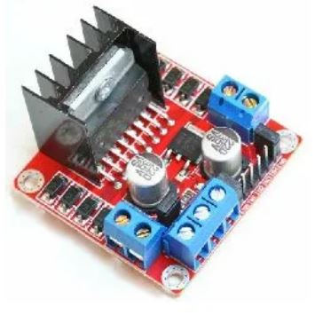
Figure 3 – The L298N (Photo property of Tronixlabs)
Unlike other motor drivers, the L298N chip itself does not have internal diodes. Rather, the flyback diodes are smd components on the module.

Figure 4- Flyback Diodes
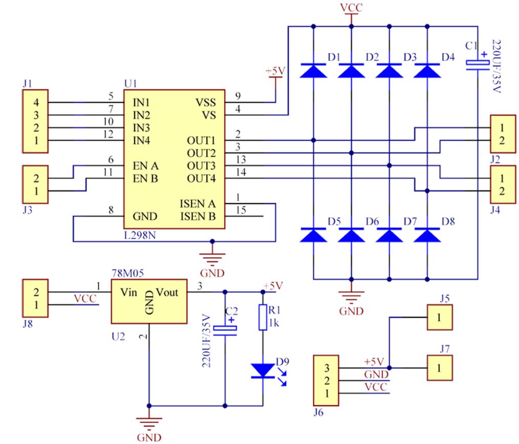
Figure 5 – Wiring Diagram of the L298N Module (Property of Sunfounder.com)
The L298N itself is a dual full-bridge driver, which is able to provide an output current of 2A when used for DC operations. As the Polulu motors are able to provide 40 mA at a no load performance, the motor driver should be able to provide a more reliable current to the motor.
The initial plan to test the module was to see how the value of the Back EMF could be read even with the fly back diodes. Which we discuss here.
The ADC
When the L298N circuit was adapted and tested, the next phase of the project was to provide an analog to digital conversion of the Back EMF values. To properly do this the output voltage of the motor must be in the voltage range close to the adc chip. To perform this a low point for the motor must be run (by setting the motor to as low of a speed as possible in it’s PWM) as well as a high point (the highest speed as possible in the motor’s PWM). To do this a potentiometer is used to act as a variable controller to adjust the speed of the motor.
Conclusion
To get a proper Back EMF measurement, the time in between cycles must be extended for as long as a time as possible in order for our ADC to grab a reading. This time is needed to help dissipate any current leftover form that cycle in order to get a more accurate reading of the Back EMF. As load of the motors can change while running the Sojourner due to varying circumstances, we would want the Back EMF to by held constant. An example of this would be a high side event the Sojourner could face. Say the Sojourner’s left rocker bogie is left in air due to a slip and the wheels are left turning. With no load the Sojourner should be able to determine that the wheels are free-spinning and that the power should be diverted to the right rocker bogie. Back EMF should be held at a constant when running the motors at a set speed, as any jumps or changes with that Back EMF could disrupt the sensorless rpm encoding we would be trying to perform.
References
Bucccini, Mark. “Easy Cruise Control for Brushed Motors Using BEMF.” E2E, Texas Instruments, 25 Oct. 2013, e2e.ti.com/blogs_/b/industrial_strength/archive/2013/10/25/easy-cruise-control-for-brushed-motors-using-bemf.
“Back-EMF Motion Feedback.” Acroname, acroname.com/articles/back-emf-motion-feedback.
“Using DC Motor Commutation Spikes To Measure Motor Speed RPM.” Precision Microdrives, Precision Microdrives, 2AD, www.precisionmicrodrives.com/content/using-dc-motor-commutation-spikes-to-measure-motor-speed-rpm/.
Sam. “Motor Drivers vs. Motor Controllers – Tutorial.” Core Electronics, 19 Aug. 2019, core-electronics.com.au/tutorials/motor-drivers-vs-motor-controllers.html.