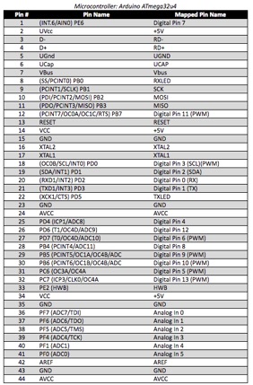
The BiPed Team:
Alexander Clavel – Project Manager
Jacob Cheney – Missions, Systems, and Test
Abraham Falcon – Electronics and Control
Mikaela Hess – Manufacturing and Design
Phong Nguyen – Manufacturing and Design
Program Objectives/Mission Profile:
By Alexander Clavel (Project Manager)
The customer has asked for a 7th generation robot that will be able to walk with the use of DC motors in replacement of servos. Based on the request of the customer, the bipedal robot will participate in the “end of semester” game. During the game, the robot will do battle with the velociraptor while using video support that is provided by the spider bot and pathfinder rover. With live video feed, the biped will be controlled with the Arxterra phone application to complete its mission.
Spring 2017 Requirements:
Project: Level 1 Requirements
By Alexander Clavel (Project Manager)
- The biped shall be able to achieve a static walk using dc motors.
- The Biped should be able to turn.
- The biped shall be able to participate in the “end of game” semester.
As stated by the customer
4. The biped shall be controlled with the use of the Arxterra phone application.
As dictated by rules of the game
5. The biped shall utilize a 3Dot board with custom SMD I2C shield.
As dictated by rules of the game
6. The biped should be able to operate for an hour.
7. The biped should be able to achieve dynamic walking.
8. The biped shall fit within the classroom cabinets (size to be determined)
As instructed by the customer
9. The biped shall be completed by the last day of class on Monday, May 15th, 2017.
As listed in the school schedule
MST: Level 2 System/Subsystem Requirements:
By Jacob Cheney (Mission, Systems, and Test)
- The BiPed shall have a Bluetooth v 4 .0 BLE Transceiver integrated circuit that will be able to communicate with an Android or iPhone.
- To maintain balance while static walking, the Biped shall use two servos as ankles to shift the center of gravity.
- The 3Dot Board shall receive commands from the Arxterra app via Bluetooth Transceiver. It will then decode and transmit data to the DC motors and servos.
E&C: Level 2 System/Subsystem Requirements:
By Abraham Falcon (Electronics and Control)
Abraham Falcon (Electronics and Control)
- The Biped will use two DC Motors for each hip for the walking movement.
- The Biped will use two Servo Motors for each ankle for a legs side movement.
- The Biped will use two Servo Motors for a turning movement.
- The Battery’s duration will last up to an hour.
- DC motor shall operate at 5 Volts for a static walk.
- Servo Motor shall operate at 5 Volts for a static walk.
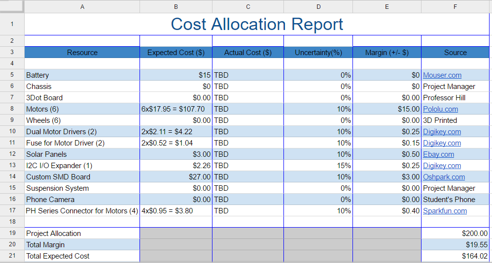
Source Material:
https://www.arxterra.com/3dot/
M&D: Level 2 System/Subsystem Requirements:
By Mikaela Hess (Manufacturing and Design)
- The Biped will have a height restriction in order for it to fit in the closet with dimensions to be determined.
- The Biped will have legs designed to hold up the weight of a 3 dot board, Arduino, servos and the DC Motors.
- The Biped shall have an implemented design that makes the legs close together for better control of the center of gravity in order to achieve static walking.
- The Biped shall optimize the constant speed of the Biped for an hour by designing a leg that optimizes each length of each step in order to play the end of the semester game.
- The Biped should add an additional feature to the static design in order to achieve dynamic walking
Design Innovation:
Alexander Clavel ( Project Manager )
Through research of previous semesters requirements and final results, we developed our own areas of focus to create solutions for. Until now, most BiPed projects utilized servos to achieve walking, but ours will require the use of DC motors. As of yet, walking with DC motors has not been achieved so that has become our main area of focus. The Theo-Jansen approach gives us an initial approach to accomplish walking. Taking the “end of semester” game into consideration, the robot will also need to be balanced and be able to turn. Some ideas that were elicited from our creative exercises were to bring the legs closer in to allow for an easier shift in the center of gravity. Using the creative method, we devised different possible solutions for these problems.
Creativity Solution Slides
Systems/Subsystem Design:
By Jacob Cheney (Mission, Systems, and Test)
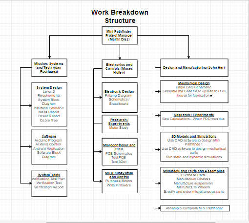
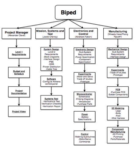
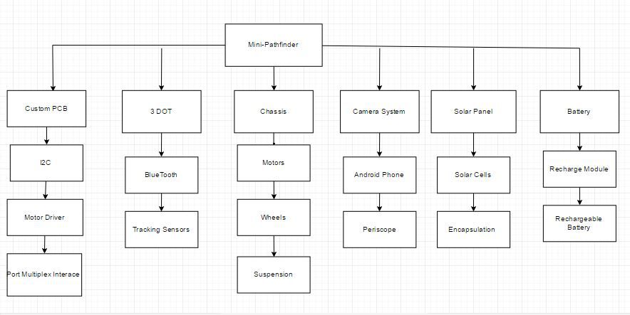
Product Breakdown Structure:

The product Breakdown Structure (PBS) is used to plan and display the outcomes of our project. The goal is to break down the product as much as possible to ensure nothing is overlooked. The hierarchical structure begins with the final product at the top followed by subcategorized elements below.
http://web.csulb.edu/~hill/ee400d/Lectures/Week%2004%20Modeling/e_Product%20Breakdown%20Structure.pdf
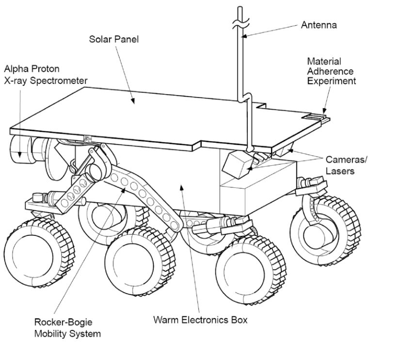
Good PBS Example (Velociraptor)
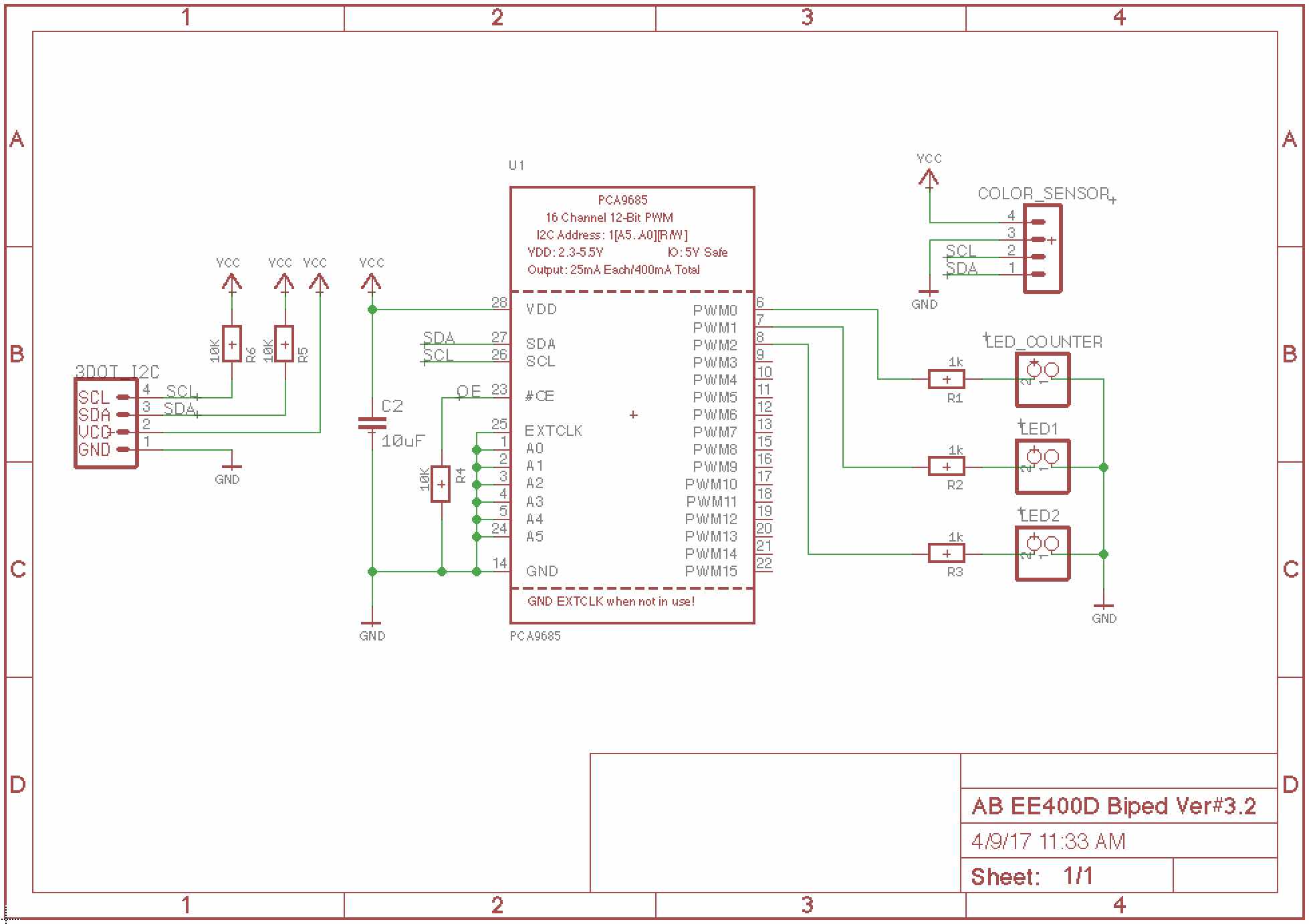
Electronic System Design:
System Block Diagram

The System Block Diagram shows the outputs for the ports of the DC motors, Servo motors, and the input for external power. The LDO 5V Regulator is used to increase the 3Dot board output voltage to the operating voltage for the Servo Motors. An Android or iPhone device with an Arxterra App will be used to control the Biped.
Source Material:
Fall 2016 Biped – Updated System/Software Block Diagrams
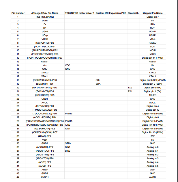
Interface Definitions

Mechanical Design
By Mikaela Hess (Manufacturing and Design)

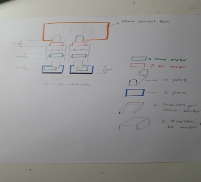
Pictured above is the initial idea that the Manufacturing engineers have designed. As can be seen above, we have the DC motors moving in the center of the body of the biped in order to have better control of the center of gravity. To make this happen, we must create a distance between the two DC motors large enough so that the two servos sized feet can be picked up and land onto the ground without disturbances. To go without the disturbances, we must create a distance of one servo between the DC motors, and an additional ⅕ of an inch of room to adjust for human error. Next, we placed the body on top of the DC motors, facing the other way in order to counteract the weight of the DC motors on either side, for better stability. This idea of having a long body was actually created from the Creative Project, where we forced a truck onto our biped design. The overall size of this Biped is to be under 10 inches. The body of the Biped is expected to be no more than 3 inches and the servo on the feet are expected to be no higher than 1 inch. With those calculations and the 1-inch radius in which the leg is designed to move around, the actual leg is to be designed in a total of 4-5 inches.

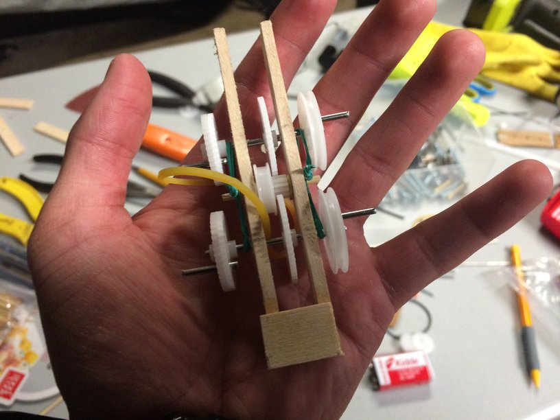
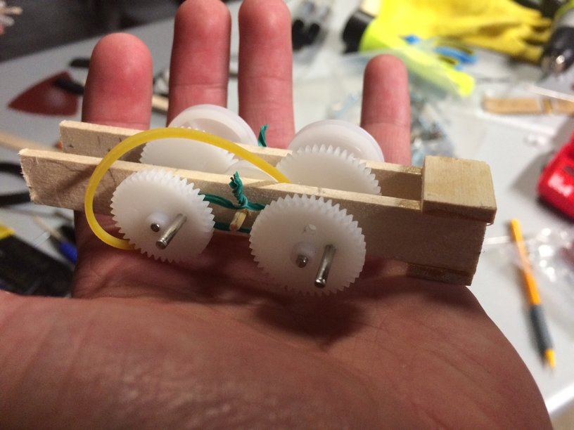
The actual walking of the biped is broken down into 5 steps here. In order to follow this design, the pictures are color coded according to the design’s components. In blue we have the representation of the circular path created by the DC motor and the pink segment. The pink segment is a sturdy piece of material that is directly linked to the DC motor and has a loose joint connection to the leg of the Biped, or the yellow piece in the picture above. Both legs start off in position one where the legs are bent and at rest at x and y equal zero on a radian circular graph. One leg then shifts its weight over by moving the leg over at an angle theta from resting position to the side by a servo. Once that is done, the DC motor then turns on and moves the pink segment to the negative pi over two positions on the same radial circular graph. This makes the body shift upward and lifts the other leg along with the body. After the segment goes to negative pi over two, it will move to pi on the radian graph, the ankle with resume its original position, causing the biped to take a step and then the legs will be programmed to reach equilibrium and resume its original position. Once that happens, the other leg repeats the same process and vice versa. Overall, the Biped should walk.
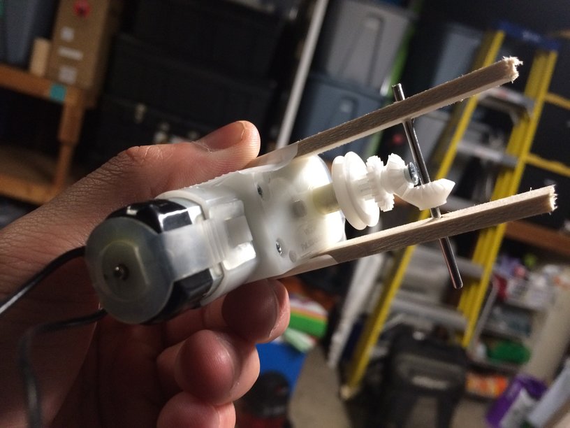
Once this design was created, I sent more photos and information to a Michael Oran Tobin, a Control Systems Engineer for California with PE Certification #CS7494. Once I had explained the servo use and parameters of the total design, it was made clear that my design would fail. What I failed to notice was the joint at the knee and the segment (yellow and pink where they connect), was that because there was no control onto that joint that the body could give out. As well, my design required precision that only DC motors with rotary encoding. A recommendation was made to use either a memory wire that straightens when current is given and loosens when there is none, or to use a servo at the knee for better control. The servo at the knee was decided to be a better option due to the memory wire being in early production and may not be able to handle the weight of the servo and leg. After going over the entire design, Michael Tobin strongly recommended doing more research on how humans walk and to consider how humans move their feet towards the center of gravity line to walk and then moves outward for better balance. As well, he suggested using a second wheel for better control of the joints. These pictures and ideas are pictured below and were made by Michael Tobin.


Overall, the design needs to reconfigured. More servos and research need to be done in order to create a working and walking Biped. The difficulty in this task is that most designs for biped are made using solely servos or stepper motors, which means this Biped leg design has to be made from scratch, but with help from other engineers and more research, it should be made possible. Also, a discussion with the project team and customer should be set up in the near future to discuss the use of more servos or motors.
Mechanical Design (Continued)
By Phong Nguyen (Manufacturing and Design)
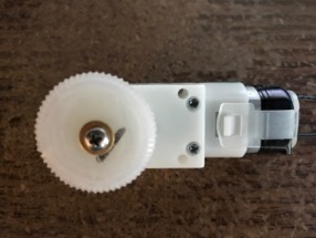
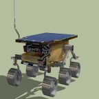
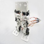
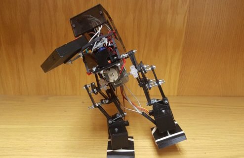
 This picture shows us a biped design based on human structure (hip, knees, and feet). As shown above, we decided to design the Biped with two DC motors for each hip, two servo motors for each ankle, and two Servo Motors for a turning movement. The DC motors are responsible for lifting up the whole leg while the servo motors will be used to shift the center of gravity. If we want to turn left or turn right, the servo motor at ankle will be able to accomplish that like last semesters biped. Under the foot, we will use high friction material such as sandpaper, rubber, or plastic.
http://robogames.net/symposium/2007/07-108-Vaidyanathan-AnnaUniv-AnalysisofBipedalWalkingRobot.pdf
http://embeddedprogrammer.blogspot.com/2012/08/simulation-of-humanoid-robot.html
Design and Unique Task Descriptions:
Electronics and Control
By Abraham Falcon (Electronics and Control)
Biped Electronics and Control Design Process/Analysis
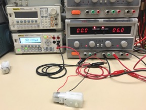
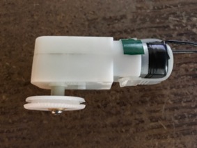
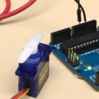
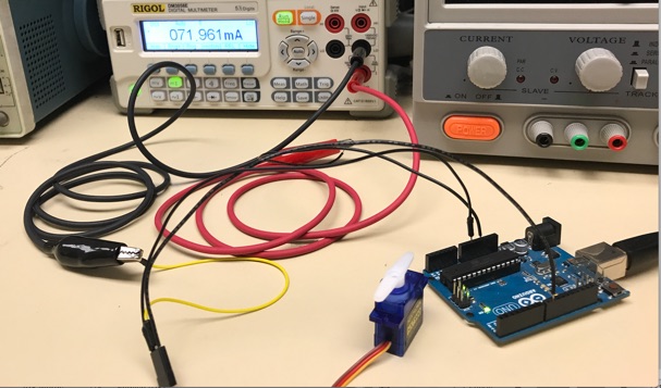
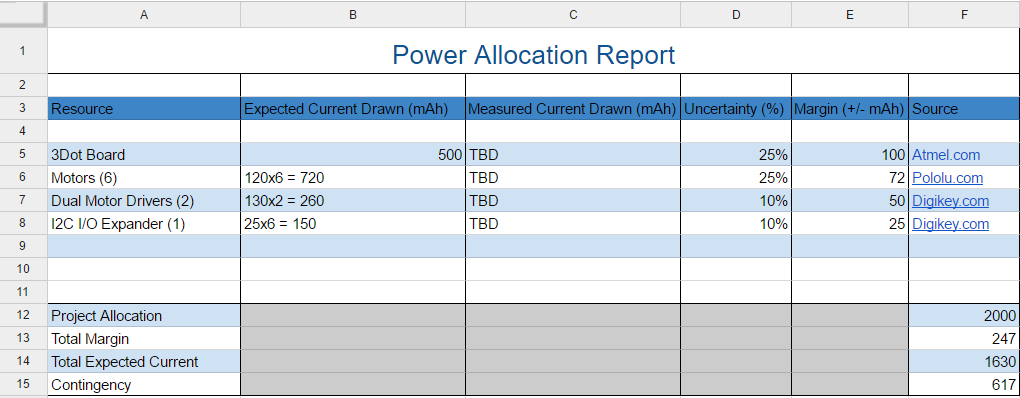
According to 3Dot Board specifications, it only supports 5V Turbo Boost for driving DC motors and for the Servo Motors to be operated at 5V. Using a rated 12V DC Motor to be power at 5V to measure the current draw at no load conditions and stall current to know the maximum current the motor will use to determine the Biped Battery total current it can supply. Also, for a Servo Motor to be power at 5V to measure no load current and stall current to determine the maximum current it will draw to know what battery is needed.
Biped Electronics and Control Tasks
- Choose DC Motors to be compatible with the 3Dot Board’s TB6612FNG Dual Motor Driver.
- Choose Servo Motors to be compatible with the 3Dot Board’s Two 3.7v Micro and Ultra-Micro Servo ports using a Voltage Regulator.
- Perform Trade-Off Study on DC Motors to select for Biped for the 3Dot Board.
- Perform Trade-Off Study on Servo Motors to select for Biped for the 3Dot Board.
- Do Servo Motor Analysis to know what are the specs on a load condition on the Servo Motor and know how much mass it can handle at its maximum current.
- DC Motor Analysis to determine the maximum current under a load condition and know what is the maximum mass it can handle.
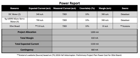
- Measure all currents of the motors to know the total current for the Biped Battery’s Specifications.
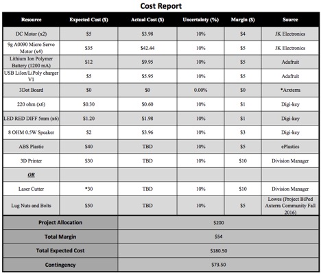
- Select a Power supply that will handle all the current that the motors are consuming.
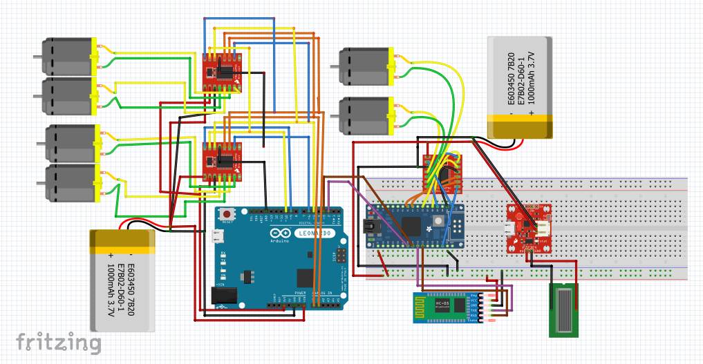
- Create a Fritzing Diagram and test it on a breadboard to assure its properly working.
- Use Eagle CAD to create an electrical schematic (PCB).
- Using Arduino IDE to program the DC Motors and Servo Motors to work properly and to be successful.
Source Material:
Fall 2016 Biped – Updated Schematics
http://arxterra.com/goliath-fall-2016-preliminary-design-documentation/
Manufacturing and Design
By Mikaela Hess (Manufacturing and Design)
Manufacturing Tasks
- Measure the cabinet’s height and reduce it by one inch and make that the height requirement (so there is room for error).
- Perform Trade-Off studies to see what implemented structures are used to make a robot walk using DC motors.
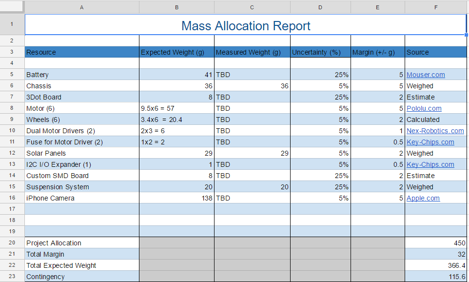
- Weigh out the servos and DC motors, 3 Dot Board, and Arduino to know the total weight capacity.
- Design a foot that has better grip and curvature for a smoother transition in steps.
- Perform a Trade-Off study to see what materials are the lightest and sturdiest material to handle the weight.


