Wi-Fi Range Extender

By Chau To

Introduction:

Wi-Fi extender or Wi-Fi booster is a device that picks up a wireless signal and then rebroadcasts that signal. It acts as a second access point for other devices to connect to. The range of a typical Wi-Fi extender is around 300ft. Some expensive Wi-Fi boosters can achieve a range of around 450ft.

Pros and Cons:

Pros:

1. The Wi-Fi extender can be a solution to solve the Wi-Fi problem at the testing point. It can be used as a second access point between the building and the test place.

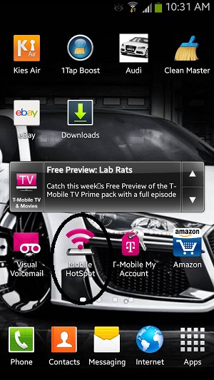
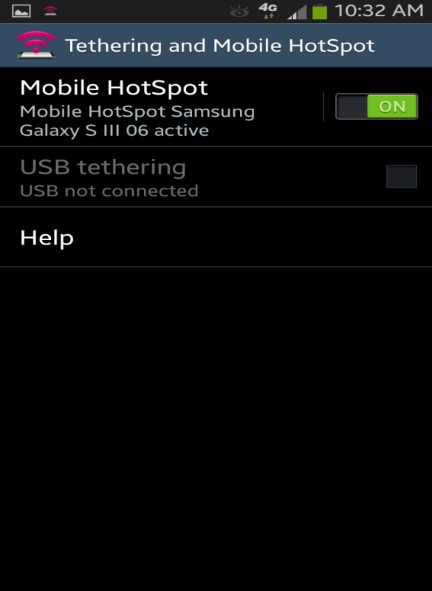
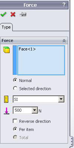
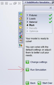
2. It is very easy to set up. There are 3 steps to set up a Wi-Fi extender. First, connect to the laptop via DSL cable. Second, launch the set-up GUI. Third choose the wi-fi signal to extend.

3. It is easy to find: Fry’s, Best Buy, online etc.

4. Quality and cost can be reviewed at this website:

http://wi-fi-booster-review.toptenreviews.com/

Cons:

1. The Wi-Fi extender always experiences 20%-50% throughput loss (the data rate loss) because it has to receive and then transmit data. As a result, the efficiency of the Wi-Fi extender is not that good. The amount of data used by Arterxa is very large because of the camera video streaming, so the efficiency of the Wi-Fi extender would affect the performance of the robot.

2. Wi-Fi extender is not very reliable. The connection is very bad especially for outdoor because of interference.

3. High-quality Wi-Fi extender can be expensive.

Testing:

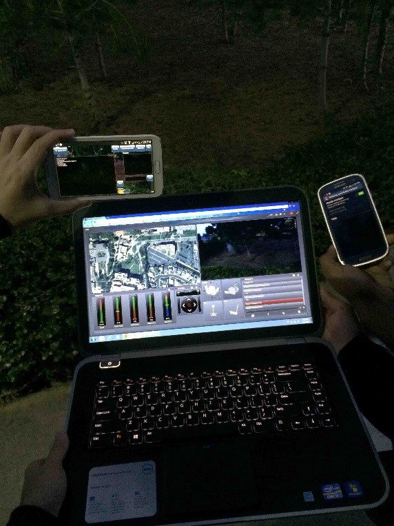
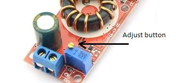
Use the Diamond WR300NR Wi-Fi Extender (in the figure) to see if it can solve the Wi-Fi problem. At the test site, we experienced many problems:

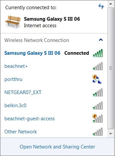
1. The Wi-Fi extender used the school’s Wi-Fi signal beachnet+ and boost that signal over the parking to the test site. The best place to place the Wi-Fi extender is around 50ft outside of the building so that it could performed at max efficiency. However, the test site and the building is 500ft apart, the Wi-Fi extender couldn’t boost the Wi-Fi signal to the test area.

2. Interference is another major problem. Although the smart phone we used to connect to Wi-Fi was in the range covered by the Wi-Fi extender, the speed was very slow. And it lost connection all the time.

3. Power could be a problem because the Wi-Fi extender connected to 120V AC power from the wall, so we had to use a long cable to connect from the building to the parking lot.
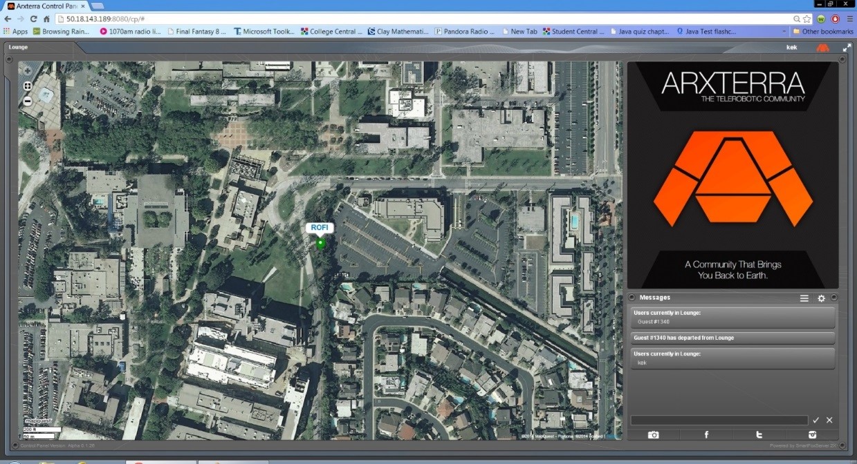
Conclusion:

The Wi-Fi extender is not a good solution for the WIFI problem because of the range and the outdoor interference. A better quality and more expensive


Smart Phone Hotspot

By Mevan Fernando and Robert Licari

Introduction by Mevan Fernando

Tethering is when a smartphone is turned into a mobile Wi-Fi hotspot and its 3G/4G data connection is shared. Once tethering is turned on in the smartphone, any device with a wireless connection can connect to the internet via the smartphone’s connection.

Procedure by Mevan Fernando

The steps taken to connect to the Wi-Fi hotspot and connection to the Arxterra Control Panel on the mobile data connection is shown below. The mobile phone used was a Samsung Galaxy S3 and the test was run at the site of the route where the robot will navigate. The following set up tutorial is performed with an android phone (Samsung Galaxy S3).

Step 1 – Click on the Mobile Hotspot app on the phone
step1

Step 2 – Turn on Mobile Hotspot
step2

Step 3 – Connect to the mobile data connection using any device with wireless connectivity (password required)
step3

Step 4 – Log in to the Arxterra Control Panel
step4

Step 5 – Start control your robot
step5

Discussion by Robert Licari

Wireless provider

The wireless provider is a simple matter considering that most, if not all, of our employees carry a cellular phone and an almost equivalent number of employees carry smartphones. Taking this into consideration, we can simply utilize the sources provided by different service providers to view their coverage maps; however, they lay claim to all areas around long beach as a part of their “Nationwide Coverage” slogans dictate. To get a more accurate map, utilizing www.sensorly.com (a free coverage map source) we can see that Long Beach is not completely covered by any of the major providers. Sensorly, however, is a user-dependent tool and is thus, not 100% accurate either, but it does provide us with an idea of actual users, in the field, using data at varying speeds from 4G down to 2G (which are relevant for our purposes). Overall, this will not be an issue considering that the field is nearby one of the many sensorly tested areas, which we can safely assume and test for signal strength and viability.

Bandwidth and Range

Our major concern is Bandwidth and Range when we consider our service provider. This factor is almost completely dictated by the amount of customers utilizing bandwidth as well as the distance the client (in this case a laptop) is from the smartphone. This is reliant also upon the service coverage area that we are working in. To be clear the International Telecommunication Union has NOT set a defined standard for the rates of mobile data services. Upon further research, one can find multitudes of numbers with even more multitudes of tests done in controlled or uncontrolled environments. The reason for this is that it is highly dependent upon the above factors and is greatly influenced by movement of the hotspot. Generally speaking, it is widely accepted that we shall be receiving approximately 300 kb/sec. To be blunt, this number is not random, but in a world where some receive 25 Mb/sec and others that receive 25 kb/sec, it is difficult to accurately pinpoint an exact number for any particular time of day. On average, 300 kb/sec will be our acceptable bandwidth, which will begin to deteriorate as we begin to venture farther and farther from our client to a maximum distance of around 50 feet.

Cost

The final concern that we have will be cost, which is, quite possibly, the most varied of our concerns because this is strictly on a case-by-case basis. One person could have an unlimited data plan, while others could have a fixed data download plan that will limit them for the experiment. For this reason, should this be the final factor in deciding whether or not this is our solution, it is simply a matter of finding a volunteer with unlimited data to have their cellular phone be a mobile hotspot.


Buy a Wi-Fi/4G access point

by Vinh Khoa Ton

Introduction

A Wi-Fi/4G access point is a location that provides users wireless network. Nowadays, most electronic devices are equipped with a wireless adapter (mobile phone, laptop, tablet, watch, etc.), the demand for wireless connection increases rapidly. The Wi-Fi hotspot could be found usually in public areas such as airports, post offices, coffee shops, or fast food restaurants while the 4G hotspot could be found almost everywhere you go. The 4G access point is a portable device that give you Wi-Fi access.

Cost and Range

Wi-Fi hotspot is quite affordable offered by most major network carriers. AT&T offered Wi-Fi on the spot with $3.99 to $7.99 per session. However, Wi-Fi hotspot is limited only to public areas that offer the service. The track field that we need to have Wi-Fi access does not have a Wi-Fi hotspot nearby.

4G hotspot (or mobile hotspot) has more coverage range and gives more flexibility for outdoor internet usage such as hiking, camping, biking at some remote areas. A hotspot device usually works well within 50 feet and could support up to 5 users at the same time.

For example, FreedomPop offers 500 MB of 4G data free every month and charge $0.02 for every extra MB used.

freedompop plan

However, the drawback is that cost for the portable hardware is expensive, ranging from $50 and up to more than $100.

freedompop price

Conclusion

The Wi-Fi hotspot provides a pay-as-you-go option that suits our need for a short project demonstration but lacks the flexibility in coverage range. The 4G hotspot could provide the needs in coverage range but the cost is too expensive. As the reasons above, we does not choose this method as our solution because it does not meet all of our requirements.


Heat and Power Problems

By Tien Dang

Introduction
Power level, power lost, and heat product are the problems that we need to maintain during testing and demoing period. To maintain the power level, we need to use a voltage regulator (https://www.arxterra.com/voltage-regulator), but power lost and heat product are always there, all we can do is deduce them to a minimum level; we can’t get rid of them.

Reducing Heat Product
When using a step down voltage regulator, a massive production of heat will be produced. The reason of this heat problem is because the different Voltage of the battery (7.4 V) and the output of Voltage regulator (6V). This difference will form extra energy, which is heat. For a long period of time, this heat will be a thread and cause fire if we do not deduce it. To prevent this problem from happening, we installed two small heat sinks under and one small fan next to the Voltage regulator.

figure 1 

Figure 1: Voltage regulator andHeat Sinks

figure 2

Figure 2: Fan and Battery

Heat sinks do not need power, so we do not need to apply any power to them; all we need that is attach them under the Voltage regulator so they can suck out the heat however the fan needs power to turn it on. For our project, we will use a separate battery (as show in Fig. 1) to minimize the power drain from the main power source.

Minimizing Power Lost
Beside the power lost due to heat converting while use Voltage regulator (which is unavoidable), the power may lost while the robot is stand by, but the power is still in the power outlet. To prevent this, we attached an On/Off button to the main battery. So we do not have to worry about the power lost while the robot is standing by.

figure 3 

Figure 3: A switch is attached to battery

Conclusion
Heat and power lost are unavoidable, but we can minimize them. Adding button to main battery, installing heat sink under Voltage regulator, and connecting a small fan next to Voltage regulator are solutions of our team. After the tests that we performed to test the movement of the Hexapod, we could see that these solutions are working very well. The voltage regulator is not getting hot or smoked, and battery can be used over ten minutes without running out of power.

Mold Case Study

By Vinh Kim, 3D Modeling and Manufacturing

Introduction:
Here I did a study on Silicone rubber (Mold Max 40 vs OOMOO 30) vs. Polyurethane rubber. The Mold Max 40 was the silicone rubber the fall 2013 Hexapod team used. I want to give our regards to Ramon Luquin (Fall 2013 Hexapod Project Manager) for donating his mold and casting material to our team.

Durability:
Here we want the rubber to be flexible as much as possible, so it does not break when bending. Therefore, we will take a look at the Elongation at Break and Tear Strength number from www.smooth-on.com.

The Elongation at Break is when the material breaks after it being pulled apart and the Tear Strength is the material that resistance to tearing. As shown in the Figure 1 and 2 that I am bending the rubber with my hand and it did not rip or pull apart.

figure 1 

Figure 1: Mold Max 40 Rubber

figure 2

Figure 2: OOMOO 30 Rubber

Product Name: Elongation at Break Tear Strength
Mold Max 40 250 % 120 pli
OOMOO 30 250 % 40 pli
Vytaflex 60 480 % 136 pli


Durability Winner:

  1. Vytaflex 60
  2. Mold Max 40
  3. OOMOO 30

 Mixing Viscosity:
Here we will look at the viscosity. I noticed that if the viscosity has a very low Centipoise (CPS) number than it will flow really easy and does not need to be vacuum degassed when mixing. If it has a high CPS number, than it requires vacuum degassing to remove all the air when mixing because it does not flow easily which will create a lot of air bubble.

figure 3

Figure 3: Mold Max 40 Mixing

figure 4

Figure 4: OOMOO 30 Mixing 

Product Name: Mixing Viscosity
Mold Max 40 45000 cps
OOMOO 30 4250 cps
Vytaflex 60 2000 cps


Mixing Viscosity Winner: 

  1. OOMOO 30
  2. Vytaflex 60
  3. Mold Max 40

What is a Shelf Life?
A shelf life is an unused product in a container that has been opened and exposed to the ambient moisture in the air.

For polyurethane rubber, from Smooth-on.com states, “Unused Part A product exposed to humidity will begin to turn from liquid to solid in as little in a few hours. Part A exposed to relatively low levels of humidity which will last two to three months in the container before showing signs of moisture contamination”.

For silicone rubber, Smooth-on.com states, “Properly stored at room temperature (73°F/ 23°C), silicone rubber will have a shelf life of 6 months from date of manufacture”.

Shelf Life Winner: 

  1. Silicone rubber( Mold Max 40 and OOMOO 30)
  2.  Polyurethane rubber( Vytaflex 60)

 Cost:
Here we will look at the cost of the 1 gallon unit and the trial size. For our group, we did not need and use a lot of rubber, so we went with 2 trial size of OOMOO 30 to mold the body and the leg of the Hexapod. 

Product Name: 1 Gallon Unit Trial Size
Mold Max 40 $96.54  $25.47
OOMOO 30 $153.03  $25.47
Vytaflex 60 $110.17  $25.96 


Cost for Trial Size Winner:           

  1.  Mold Max 40 and OOMOO 30
  2. Vytaflex 60

 Cost for 1 Gallon Unit Winner:

  1. Mold Max 40
  2. Vytaflex 60
  3. OOMOO 30

Conclusion:
Overall, I think the OOMOO 30 is the best rubber to buy because of the trail size cost. Also the shelf life is so much better and last longer than the polyurethane rubber and it does not require vacuum degassing when mixing. Plus the durability is pretty good. I recommend when purchasing molding material, remember look for the durability, mixed viscosity, shelf life and cost.

References:

http://www.smooth-on.com/Silicone-Rubber-an/c2_1113_1135/index.html

http://www.smooth-on.com/Silicone-Rubber-an/c2_1113_1136/index.html

http://www.smooth-on.com/Urethane-Rubber-an/c6_1117_1142/index.html

http://www.smooth-on.com/faq_display.php?faq_id=99

http://www.smooth-on.com/Silicone-Rubber-an/c2_1113_1135/index.html?catdepth=1

http://www.smooth-on.com/Silicone-Rubber-an/c2_1113_1136/index.html?catdepth=1

http://www.smooth-on.com/Urethane-Rubber-an/c6_1117_1142/index.html?catdepth=1

How to perform a Stress Test

By Vinh Kim, 3D Modeling and Manufacturing

Introduction:
Here I will show you how to perform a Stress test using Solidworks and SimulationXpress Study for the Hexapod leg and bracket design to determine its maximum stress level.

Leg Stress Testing:

figure 1 

Figure 1

First, open Solidworks and open the leg design the user wants to test.

 figure 2

Figure 2

Click on “Evaluate” and next on the top right click on “SimulationXpress Analysis Wizard”

 figure 3

Figure 3

Now, on the box on the left side using the mouse, right click, and click on the “Apply/Edit Material”

figure 4 a 

Figure 4 a                                                                   

figure 4 b

Figure 4 b

A Material box will show up. Now pick any material that the user wants to test. I picked 6061 Alloy because SolidWorks already had the value in auto set so simply click apply and close.

figure 5 

Figure 5

Now, right click on fixtures than click on fixed geometry.

Figure 6 

Figure 6

The Fixture box will show up. As shown, here I clicked on the four holes than a green arrow will pop up and that means that this will be the precise location where the user chose. When done, just click on the green check mark on the left side.

figure 7

Figure 7

Now, right click on the External Loads and click on the Force and apply the force.

figure 8

Figure 8

figure 9

Figure 9                                                                                                                                         

When the leg is sweeping, Figure 8 shows the wrong way of applying the force at the bottom on the leg and Figure 9 shows the right way of applying the force at the bottom from the side.

figure 10 

Figure 10

Now in the Force box, I set the force to 500 N and click on the green click mark

Figure 11

Figure 11

Figure 12

Figure 12

When finish setting the force number, in the left side the user will see a box (similar to Figure 11) than click next three times and click Run Simulation (Figure 12)

Here is the video of the leg sweeping: http://youtu.be/z0AmgpNLJIg

Figure 13

Figure 13

Click on the Factor of Safety (-Max von Mises Stress-) and the user will see a lot of red that mean that the force of 500 N is pretty high, so I am going to lower the force and rerun the study until we see all blue and that will be are maximum force.

 Figure 14

Figure 14

At 102 N, we see a little red.

Figure 15

Figure 15

At 101 N, we see no more red, so this is our maximum force for this leg design.

Bracket Stress Testing:

fig16

Figure 16

fig 17

Figure 17

Here I am using 6061 Alloy again and applying fixtures in the bottom (green arrow) and force of 30 N on the top (purple arrow).

Figure 18

Figure 18

On the left hand side click next three times and run simulation.

Here is a video of the bracket bending: http://youtu.be/RigGvNsRHT4

Figure 19

Figure 19

This is at 30 N and you can see all the red, which is not good because it will break. Rerun the test again now lowering the force down.

figure 20 

Figure 20

Here we find out that the maximum of this bracket is 6 N.

Conclusion:
It is recommend to manufacturer that when designing any types of robotic model. They should always consider of using Solidworks SimulationXpress Study to check their design and use different material to run simulation to test their design if its strong enough to handle all those pressures and burdens that will be placed on the robot.

Voltage Regulator

By Tien Dang

Problem Statement
Base on current test and calculations from discharge rate of current (available at https://www.arxterra.com/current-draw), we noticed that the battery provided 7.4V and 5000mAh, while each servo only required 6V (maximum) and 450mAh (with full load) to work. Essentially, the servos could burn without something to step down the voltage.

Solution
To prevent an overload voltage and current, we chose to use a voltage/current step-down regulator to limit the current as well as the voltage that going into ADK board and the servos.

figure 1 

Figure 1: Voltage step down regulator

figure 2

Figure 2: Equivalent Circuit

With this particular voltage step down regulator, we can limit the voltage and current that flows through the servos and ADK board.

Set up process
This Voltage regulator has a DC input and a DC output. All we need to do is connect the source to the input and use a voltage meter to measure the output voltage. We can adjust the voltage by turning the Adjust Button using a flat screwdriver.

figure 3figure 3 a

Figure 3: Adjust button and flathead screwdriver.

After adjusting the voltage to a prefer level (in our case we adjusted to 6V), the Voltage regulator is ready to use. All we need to do is connect the output into an outlet and ready to apply power into applications.

Android Phone Complications with Arxterra Robot Application

By Tien Dang

Introduction
ArxRobot is an application for Android phone that allows users to control their robots wirelessly through Internet command (panel website: http://cp.arxterra.com/#). For this project, we will be using this application to control the Hexapod for walking sequence and traveling over objects on the testing field.

Trouble download and connection
In order to download the App from Play Store into the phone, we need an Android phone with version of Android 1.6 or higher. Although, there are other phones that allow you to download the App and use it but there are few of them (?) can’t recognize the USB from your phone and the Microcontroller ‘s USB ( a test had been done using a  Samsung galaxy SII (SGH-R760), Samsung galaxy S4 (SGH-M919) , Samsung galaxy S3 (SGH-T989) and found out that these phones are not recognized by the USB from the ADK board, due to the phones IOIO-OTG were not supported). To check that if the phones are compatible with IOIO-OTG or not, the user can visit at https://github.com/ytai/ioio/wiki/Supported-Devices. There are certain cases that the user phone is compatible with the IOIO-OTG, but is not compatible with the App. (I have tested HTC WildFire S)

 figure 1

Figure 1: Compatibility of HTC Wildfire S from https://github.com/ytai/ioio/wiki/Supported-Devices

figure 2

Figure 2: Compatibility of HTC Wildfire S when downloading the App.

Solution
If your phone is not compatible with the ArxRobot App, we have no choice besides using another phone. Incase if your phone is not compatible with the IOIO-OTG USB. All we need to do is unlocking the bootloader from your phone and install the USB driver into it.

What is a Booloader?

Bootloader is a piece of code that runs before any operating system is running. Bootloader is used to boot other operating system and usually each operating system has a specific set of Bootloader for it. For the new phones such as Samsung Galaxy S.x, bootloader is actually locked. The guide that shows how to unlock Bootloader can be find at http://www.addictivetips.com/mobile/what-is-bootloader-and-how-to-unlock-bootloader-on-android-phones-complete-guide .

Advantages and disadvantages of Bootloader

figure 3

Figure 3: Screen shot while unlocking bootloader

If the user decided to unlock the Bootloader for their phone, the phone will show the picture as Fig.3 demonstrated. The user phone’s warranty will be voided, and could cause some applications on their phone to not work properly. But on the other hand, they will be able to install and custom any drivers for their phone as desired.  For an Android phone version of 4.3.x and up, the developer team has not been able to unlock the bootloader at this point of time yet. So there is no way we can control the Microcontroller board via Internet if we own an Android with version 4.3.x or beyond this version.

Hexapod Coding Preferences

 By Chau To

  • Introduction:

This blog post will discuss some issues of the servo library (Servo.h) and how coding of the Hexapod was built including functions and subfuctions as well as some tips and troubleshooting.

Note: Hexapod team drives 19 servos directly from the Arduino board (digital I/O pins), and it uses the built-in Servo.h library functions such as “write” and “attach” as the main code to rotate the servo shaft. If your hexapod uses an additional servo controller boards such as the Adafruit etc, some of the materials discussed in the post would not apply in that situation.

  • How to create object servo in the Servo.h library:

Since the coding will require “for” loops, creating individual servo object such as servo1, servo2, etc.. Similar to the example in the Ardunino websites is impossible. The only way is to create an array of servo object. How can we do it? We can define a number of servo then call the servo library to create and array of servo object:

#define number_of_servos 19
Servo servos[number_of_servos];

So, we will have an array of servos; in this example, we will have array of 20 servos. Each servo will be appearing like this servo[1], servo[2], etc… NOW! We can put these into for loop. For example: servo[i].write(180).

  • Array:

Array is very important. As mentioned above, when we run “for” loop we need to use array because it will optimize our coding. An array of digital I/O pin is a great example since we need to attach each servo to a specific pin on the Arduino. Here is a sample code:

int pins[] = {30,31,32,33,34,35,36,37,38,39,40,41,42,43,44,45,46,47,48};

void set_servos() {

  for (int i=0; i<number_of_servos; i++)  {

    servos[i+1].attach(pins[i]);

     }}

The above example is a simple function I wrote to attach the pin to the servo. My digital pins will be from pin 30 to pin 48 of the ADK board.

The same concept applies for the servo’s shaft angle rotation. If user wants a specific servo to rotate at a specific angle, they can make an array of angles and run it in a for loop. More detail about array of C++ can be found at: http://www.cplusplus.com/doc/tutorial/arrays/

  • Subfunctions:

Subfunctions are smaller functions that will be called in a main or larger function. Breaking a long and complex function into smaller subfunctions is very useful because it’s easier for the user to double-check and debug the code.  For example, one of the main function of the hexapod is run which includes 2 stages; first stage is moving the femur, tibia, and shoulder to a new position, and second stage is to bring them back to the initial position. So, we can break these 2 stages into 2 subfunctions. And, even smaller subfunctions for controlling and debugging.

  • Serial Monitor:

Serial Monitor can be turned on by Ctrl+Shift+M after uploading the code into the Arduino board. The serial monitor is extremely useful when testing the code. It’s used to keep track of the codes and fix all the bugs before uploading to a real model. This is the sample of the serial monitor added in my set_servo function that was discussed in the previous part:

void set_servos() {

 for (int i=0; i<number_of_servos; i++)  {

    servos[i+1].attach(pins[i]);

    Serial.println(“attach pin”);

    Serial.println(i+1,DEC);

    Serial.println(pins[i],DEC);

  }}

With these serial function added in, I can monitor for my loop as well as to see which servo had attached to which pins. The serial monitor is available at: http://arduino.cc/en/reference/serial

Note: In order to run the serial monitor, in the setup you have to call the serial.begin

void setup()

{

 Serial.begin(9600);

figure 2

Figure 2

How to use STL file cutting

By Vinh Kim, 3D Modeling and Manufacturing

Introduction:
To print out 3D materials, the Manufacturing Division Manager Ali Etezadkhah will provide his own 3D printer that can print 5 by 8 in parts. In some cases, the 3D printer cannot print larger parts because its size is too small. In order to cut down the size of the model, we have to use a program call STL (Surface-Tesselation-Language) so that it will fit the 3D printer for parts print out.

STL Step by step guide:
Here we have a model from the rover team where we have to use STL file to cut the parts.

figure 1 (1) 

Figure 1

Step 1:

 figure 2

Figure 2

Go to www.netfabb.com and download the netfabb Basic since SolidWorks program cannot cut the STL file. Now open the netfabb program than open the STL file.

Step 2:

figure 3

Figure 3

Here we see that the model length is 140 mm (5.51181 in) and the width is 150 mm (5.90551 in), (as expected, the model is too large).

Step 3:

Next, go to Extras and click on the Free cut (Pro).

figure 4

Figure 4

Step 4:

figure 5

Figure 5

A product information menu will pop up which telling the user that we need netfabb Professional is required to use. It costs 1,799.00 USD to buy on the netfabb website. In this case, we do not need to buy the license program since the netfabb basic will cut the STL model too so just close the window.

Step 5:

figure 6

Figure 6

From the box on the right hand side, we can see cuts (X,Y,Z). Just use the X and move the bar to 70 mm because 140/2 = 70 mm and click Execute cut.

Step 6:

figure 7

Figure 7

Now, on the bottom right side, click cut.

Step 7:

figure 8

Figure 8

Next, click on the model (right side) and it will turn green. Now, right click on the mouse and go to export part as STL and save it. Finally, use the same method for the left side of the model.

Conclusion:
For the hexapod, we also used this program to break down our parts since the body is too big for the 3D printer (size … ). The STL file will cut it into four pieces and later will be printed parts by parts. Everything will be compressed into a STL file and sent to Ali to print out the pieces.