Molding Parts

By Vinh Kim, 3D Modeling and Manufacturing

Introduction:

Here I will show you the process of molding and casting the Hexapod parts with pictures.

Tool & Supplies:

  1. Sliding Compound Miter Saw
  2. Hardwood Flooring
  3. Mold Max 40 or OOMOO 30
  4. 3D- printed parts
  5. Glue gun & hot glue
  6. Ease Release 200
  7. Vinyl gloves only (Latex gloves will inhibit the cure of the rubber)
  8. Drill
  9. Screws
  10. Digital Scale
  11. Measuring Tape
  12. Disposable plastic cups
  13. Safety Glasses
  14. Utility knife
  15. Clamp
  16. Disposable Wooden Chopstick

Making the Mold Box

figure 1

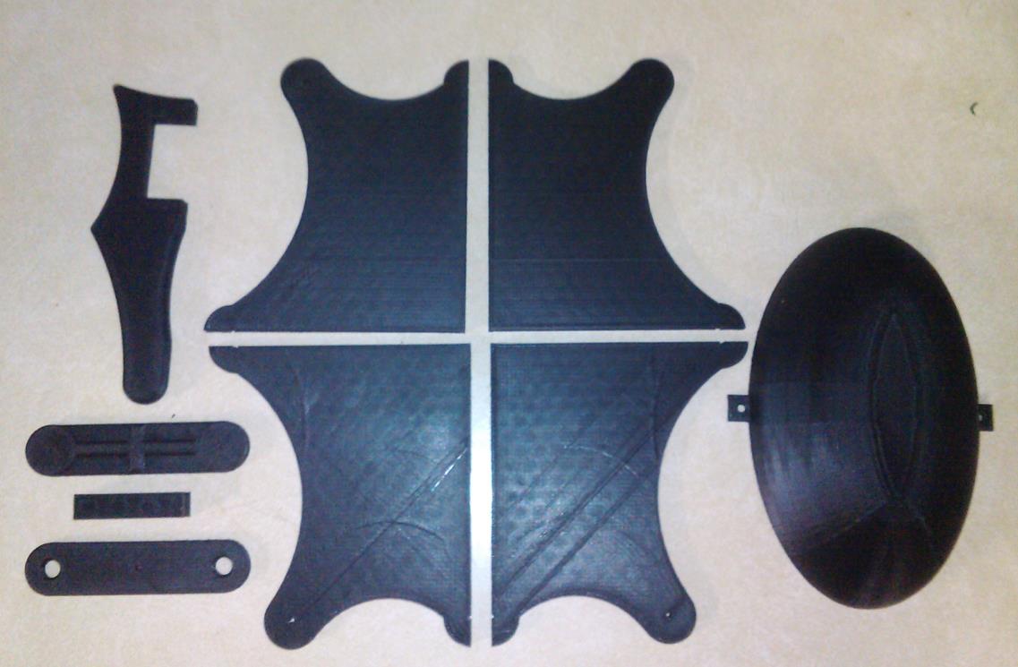
Figure 1: Thank you to Ali the manufacturing manager for printing the Hexapod parts. Here I have the Hexapod 3D printed parts ready.

figure 2

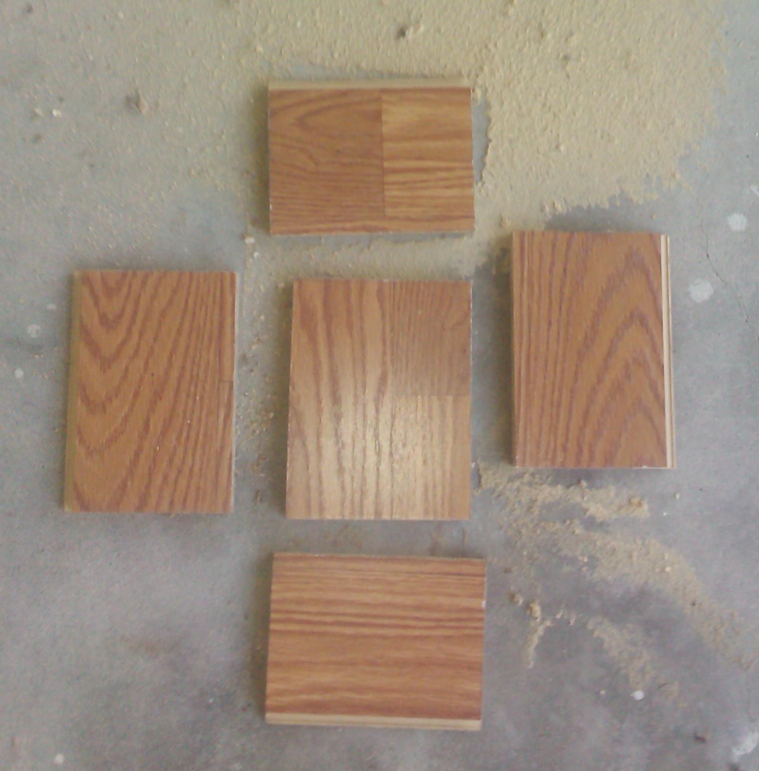
Figure 2: Here I measured (minimum of ½” of space on all sides of model see Figure 5) and cut the hardwood flooring using a sliding compound miter saw.

figure 3

Figure 3: Using the two free 12 in. Ratchet Bar Clamp I got from Harbor Freight by using a coupon to clamp the wood that I cut together, so I can drill the holes and put the screws in. Here I am using a M3-0.50 x 12 mm screws, than I used a drill bit size 2.50 mm to punch the holes.

figure 4

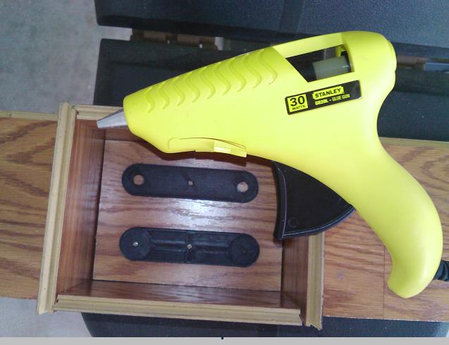
Figure 4: Next I used a 1.60 mm drill bit to drill the holes in the 3D printed parts and screwing the model down with a M2-0.45 x 12mm screw to prevent the 3D parts from moving. Also to prevent rubber from leaking out of the mold box, I used hot glue to stick it around the interior edges.

figure 5 a     figure 5b

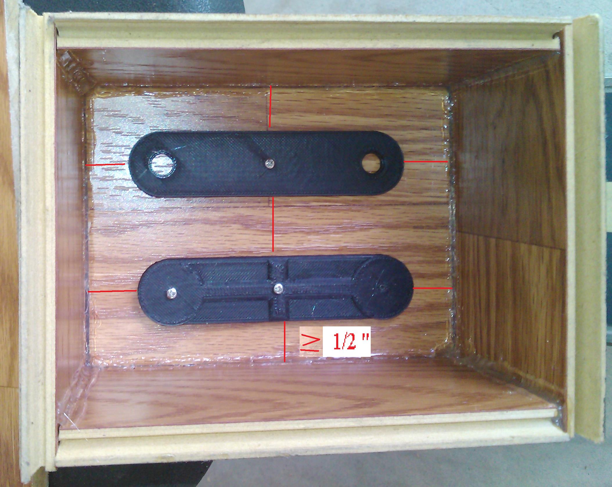
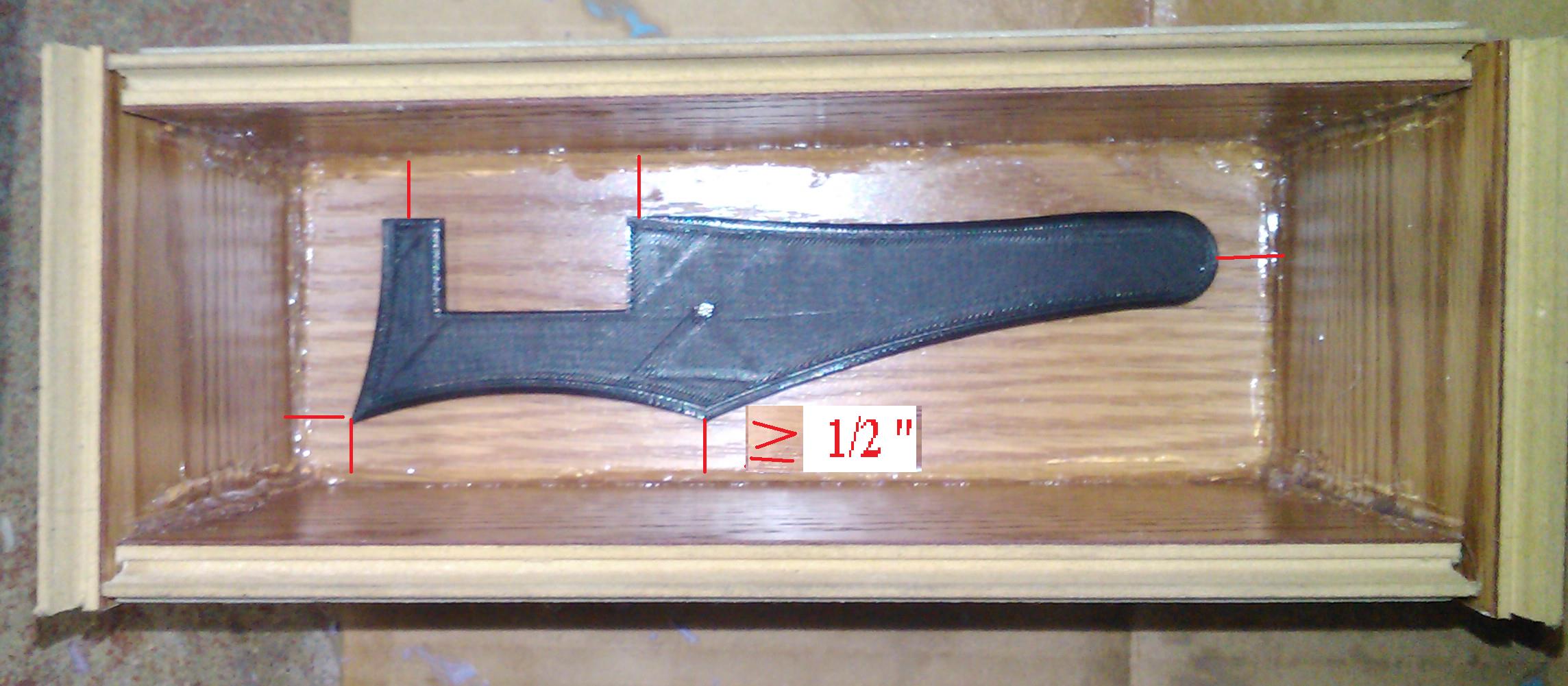
Figure 5a: Mold box done.                                      Figure 5b

Pouring Mold Rubber

figure 6

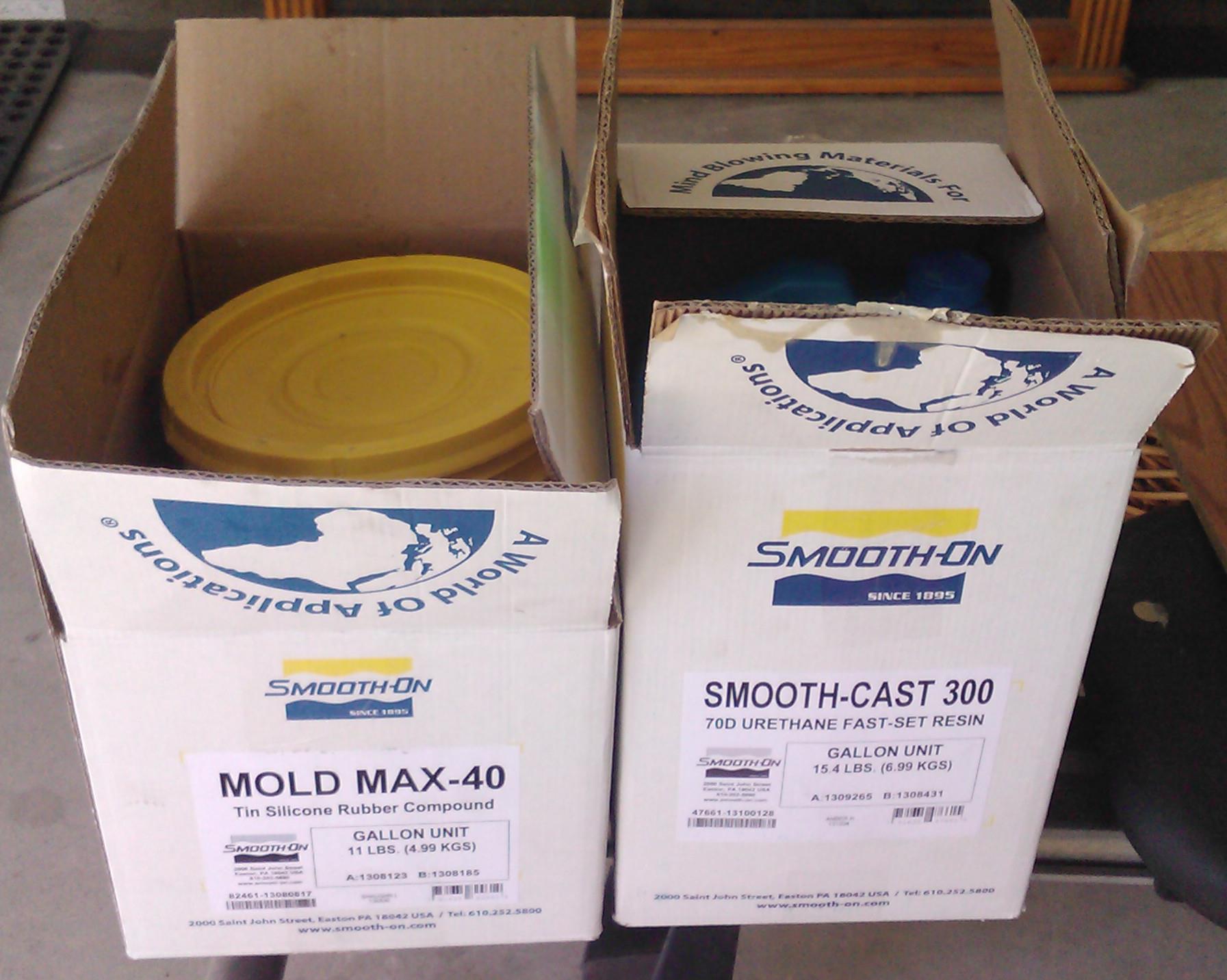
Figure 6: Once again, thanks to Ramon Luquin (Fall 2013 Hexapod Project Manager) for donating some mold and casting material to the Hexapod team.

figure 7 

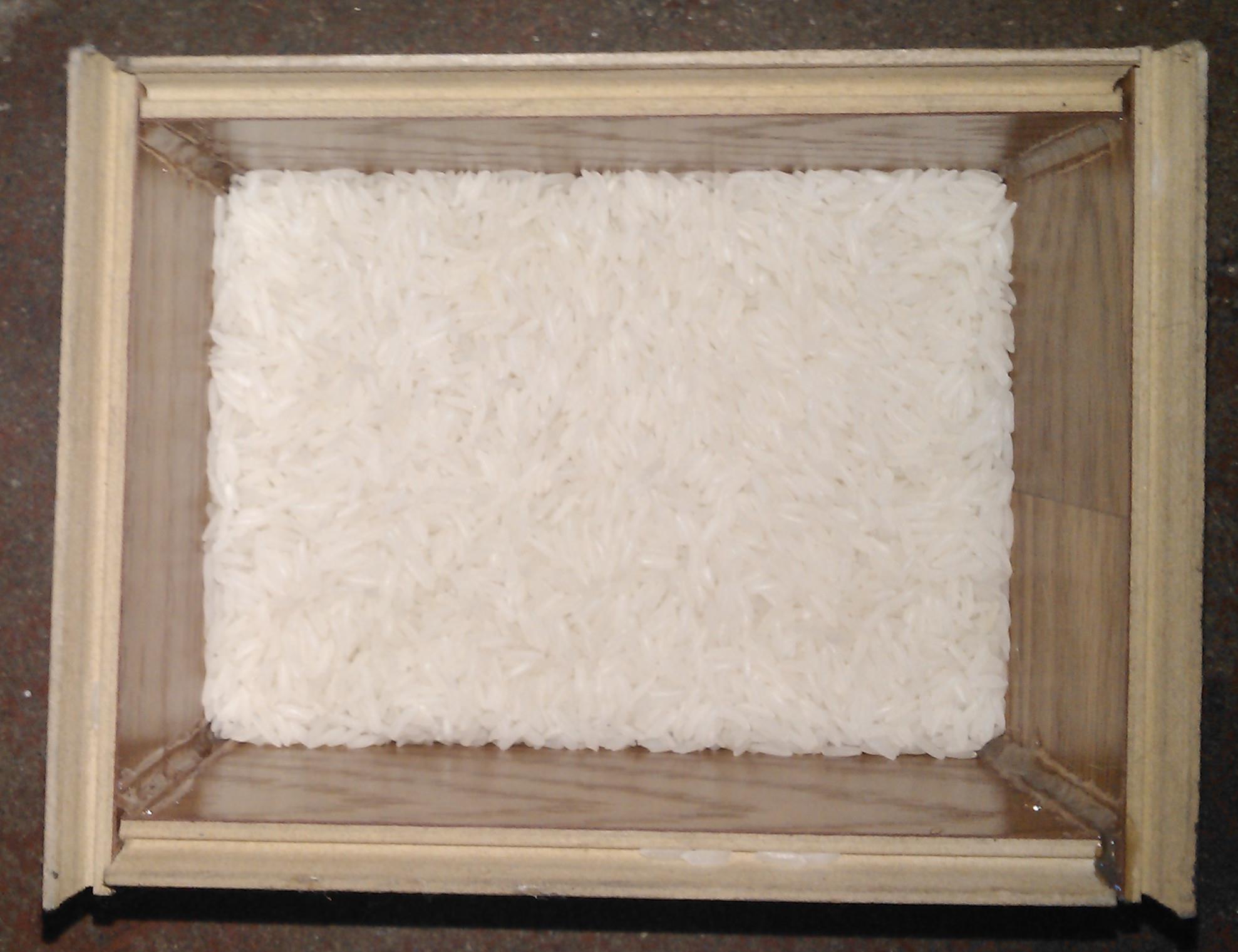
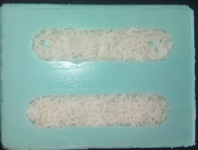
Figure 7: Here I’m using rice to estimate amount of rubber or you can go online at http://www.smooth-on.com/tools.php to use a Material Calculators “How much liquid rubber do I need?”

figure 8

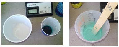
Figure 8: Using Mold Max 40.  It will be mixed in a 10:1 ratio. I am using 8 oz for Part A, 0.8 oz for Part B than mixing it together. Vacuuming is required to remove all the air bubbles. When mixing, just make sure to keep mixture stick on the bottom of the container and scrape the sides of the container. Than keep on swirling in circle until you get a solid green color.

As for OOMOO 30, I need mix a 1:1 ratio than I would use 4.4 oz for Part A and 4.4 oz for Part.  However for this particular kind, it’s not required to vacuum this product since it has a low mixed viscosity.

figure 9

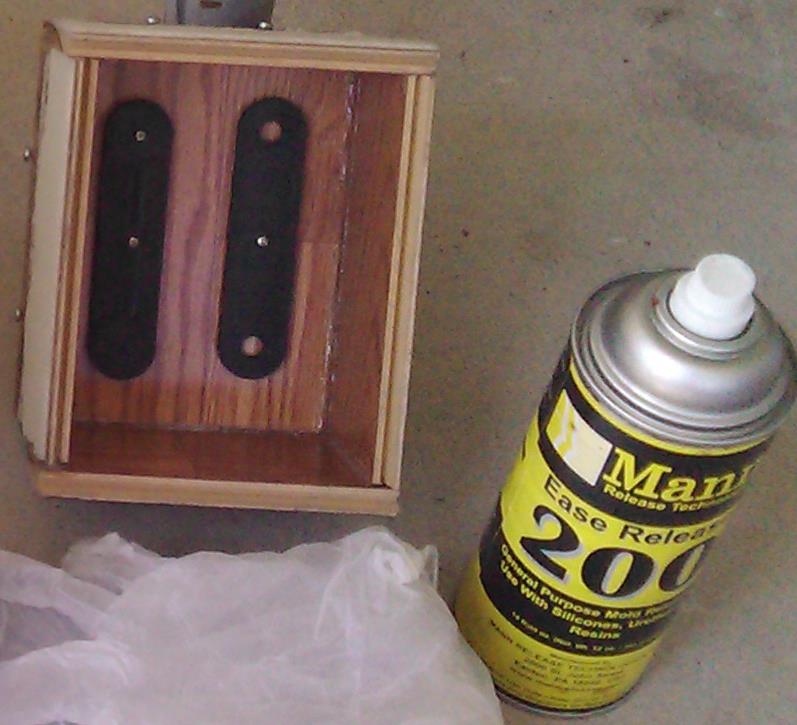
Figure 9: Spray a light-mist coating inside the molding box, so when you remove the rubber it does not stick to the model.

figure 10 

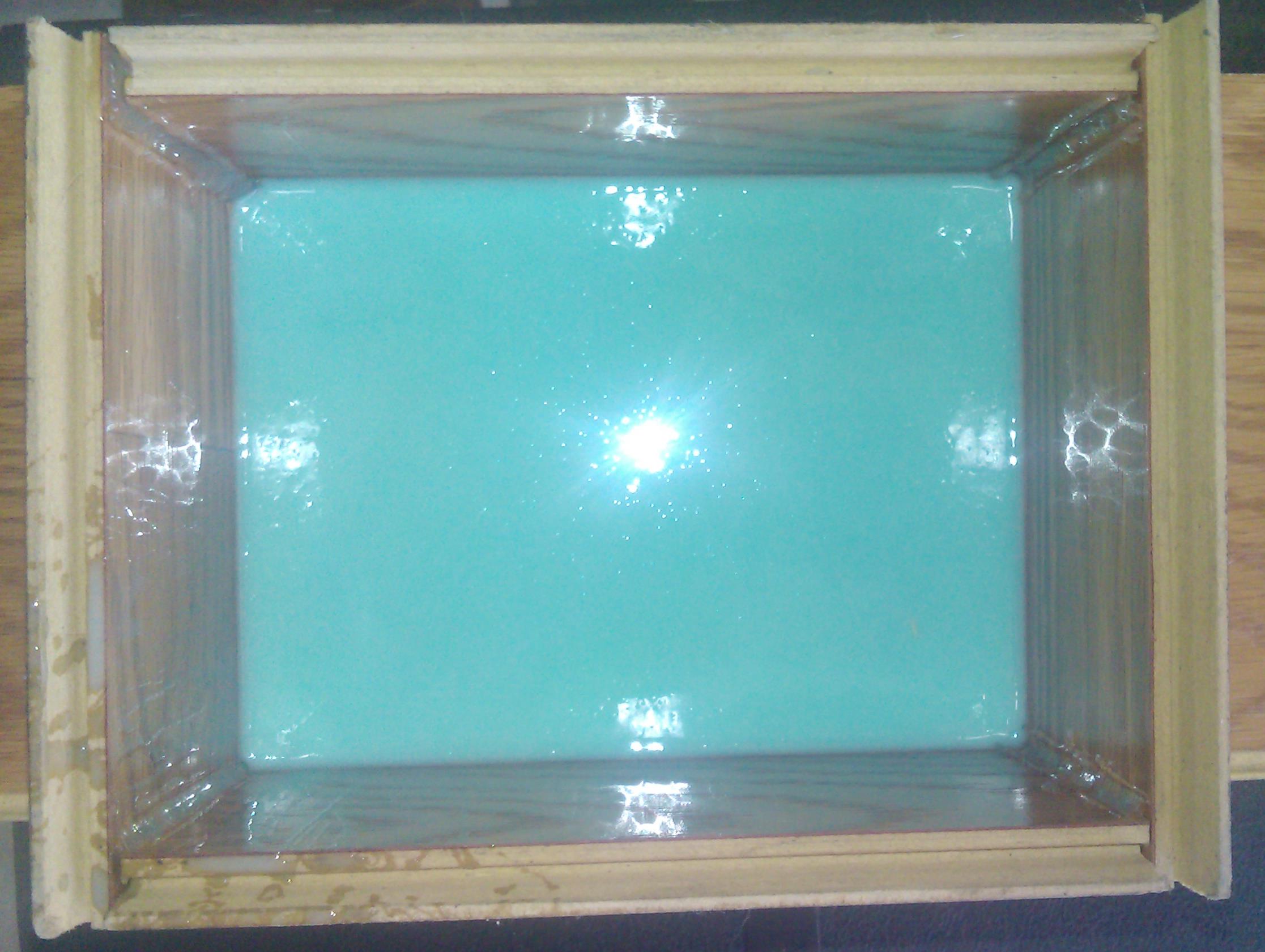
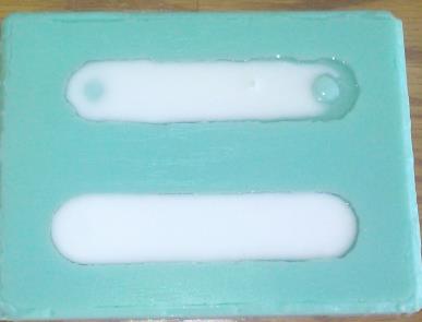
Figure 10: To prevent air bubbles. Pour the rubber into a corner of the mold box and allow the rubber to flow evenly throughout the model. Let it cure and rest for 24 hours.  OOMOO 30 only required 6 hours to form.

figure 11 

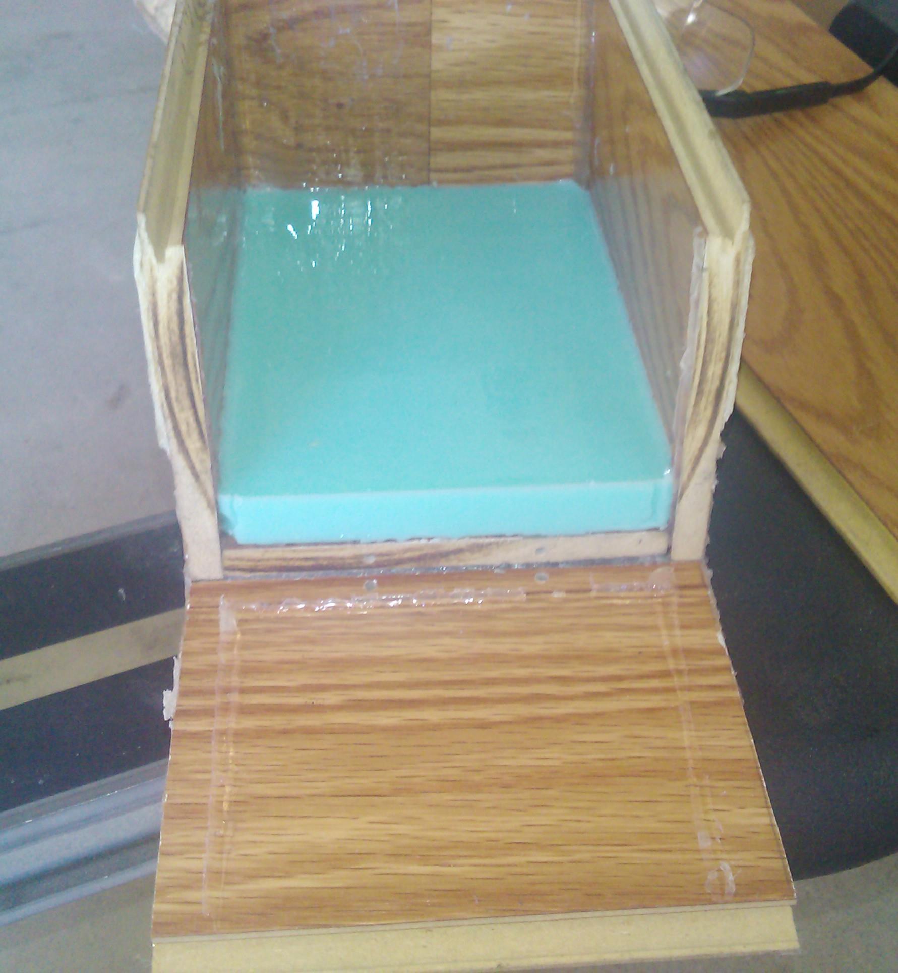
Figure 11: Finally, after rubber has cured, remove the retaining walls away from the cured mold.

figure 12 

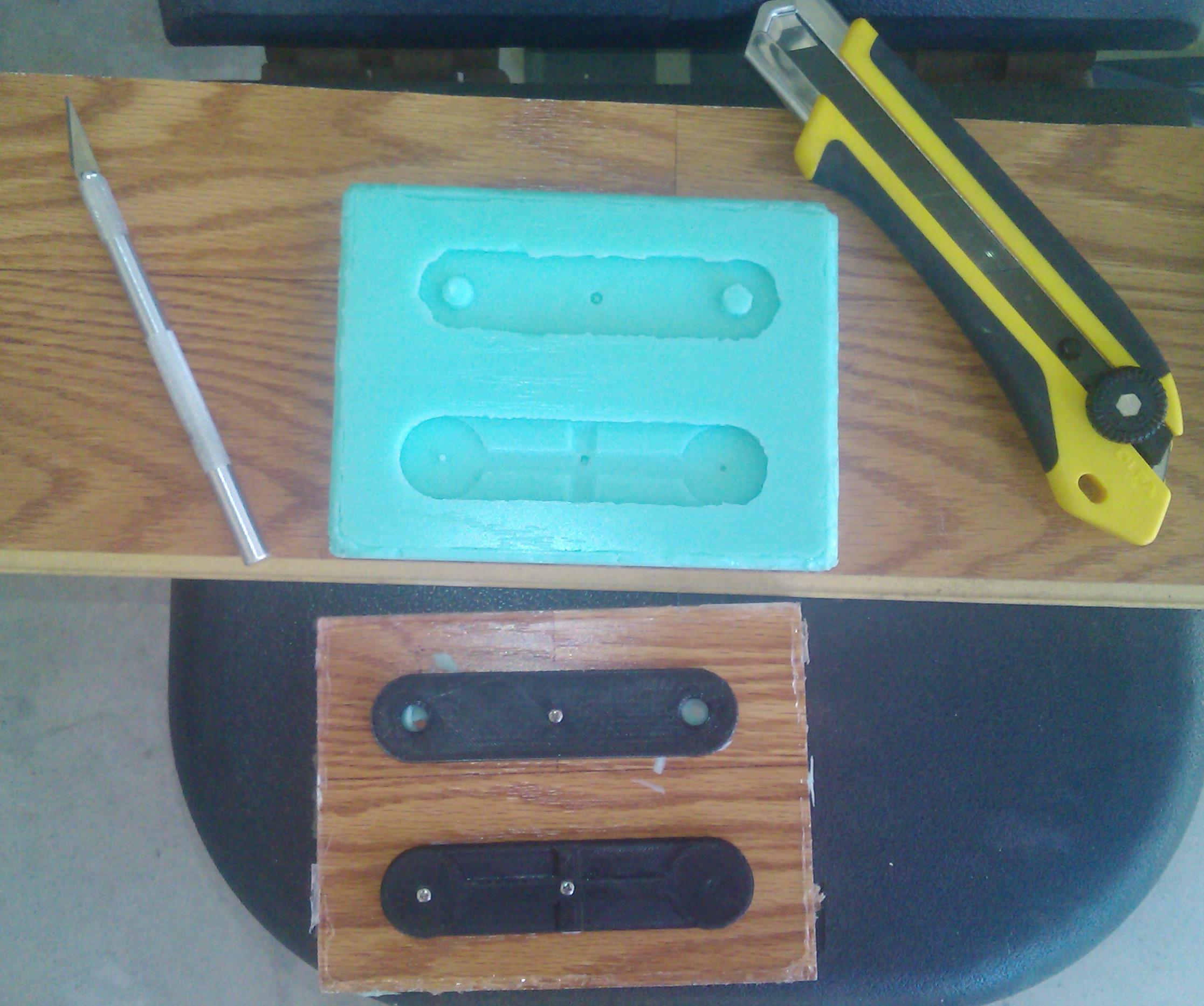
Figure 12: Molding done.

“HEXAPOD – the Movie” Trailer

By Mason Nguyen – Project Manager          

A short trailer that was filmed by our team during this semester!!!

https://www.youtube.com/watch?v=3NniqIkw-64&feature=youtu.be

Budget Report

By Mason Nguyen, Project Manager

For a project, it is important to have well prepared detailed budgets cost in order to meet its goals and objectives. Detailed budgets will be included with the name of the item, item quantity, production location, shipping cost and total cost. Here is our final budget report.

Untitled-1

Following from the presented mission objective budget that was stated here (https://www.arxterra.com/mission-objective/), our team managed and maintained the budget within $500 range. In comparison to previous projects, our budget seems to be the lowest because we used an ADK board where it has a built in USB slot. Link to ADK board (https://www.arxterra.com/hexapod-adk-board/)  

However, for the Arduino Uno it does not have a USB slot so the user needs to buy another board that has a USB slot and connect it them together.  In addition, the Arduino Uno does not provide enough space to connect all 18 pins for the servos. It requires the user to use two ADA fruit servo shields to connect all the pins together.  Our team budget could have been less than $500 since we only needed 18 servos to operate the hexapod but we added an additional servo as a phone holder to observe and scan the area. 

How to replace metal gears and burnt circuit board from broken servos

By Tien Dang

 Introduction
During the project (hexapod), we broke total of four servos. After observation and analysis from the broken servos, we able to detect and identify two problems of how the servos were broke down, while the servos are running. First problem we encountered is overload in power, and the second problem is overload in weight.  So we took some time looking inside of the broken servos and found few solutions way to fix them.

What does inside of a servo look like?
Servos usually contain three parts (metal grinding gears, motor and circuit board)

figure 1 

Figure 1: Take apart servo with a screwdriver

figure 2 

Figure 2: Metal gears

figure 3

Figure 3: Motor and circuit board

How to fix broken servos?
To detect which problem servo met, we connected the servo to the board as we testing the servo.

  1. Power overload

This problem is usually meet when we first buy the servo and test right away without adjust the voltage to 6V or limit the current that goes by the servo.

figure 4

Figure 4: Circuit board inside the servo

For the power problem, three cables (black, white, red) will usually falling off from the soldering node or the chip is tanned. If the soldering parts are failing off, simply re-soldering it, if the chip is burnt, we have no choice but to replace the whole board (use the broken gear servos to exchange the board)

2. Weight overload 

This problem usually occurs when the team is testing the hexapod movements (forward and backward). The weight distribution usually does not equal for each legs, all of the weight will be putted on the back legs (which simply cannot create enough force to push the whole body moving forward). This will result into two problems. One is current over-drain, and the other is broken gears metal.

figure 5

Figure 5: Broken gear metal

For the current over-drain problem, we can repair it by using the same methods as power overload. For the broken gear metal, we need to replace the gear. We can buy the new metal gears online at the website http://www.amain.com/advanced_search_result.php?keywords=metal+gear&x=0&y=0. Then we can exchange the broken gear with the new ones. Instead of paying $12.50 to buy a new servo, this method will save a lot of money since one metal gear only cost $0.99 up to $4.99 compared to $12.99.

Conclusion

After looking inside four broken servos, I was able to exchange metal gears and burnt board for two of the servos. They are working and running smooth like a brand new servo. In case if we stumbled into this problem again while demoing the project, I will be able to dismantle the servo apart less than 5 minutes and exchange the broken parts without taking the whole hexapod apart (like we did from beginning). Save time and money!

Here is the picture that I replaced and exchanged metal gear without take apart or re-wiring the robot.

figure 6

Figure 6: Exchanging the broken metal gear for one of the leg.

figure 7 

Figure 7: Broken metal gear in middle leg’s servo 

Casting the parts

By Vinh Kim, 3D model and manufacturing

 figure 1

Figure 1: Here we will be using Smooth-Cast 300.

 figure 2

Figure 2: I used rice to measure the volume or you could go online at http://www.smooth-on.com/tools.php to use a Material Calculators “How much liquid plastic do I need?”

figure 3 

Figure 3: Using the resin molding Smooth-Cast 300, we will be mixing .55 oz for cup A in one and .55 oz for cup B. During the mixing process, make sure to pour the liquid from cup A into cup B and blend it fast (the resin will harden in 3 minutes so make sure to mix it fast) and carefully pour the combined mixture into the rubber.

At this time, the resin will turn white, so let it cool down for about 15 to 30 minutes than take it apart. Now, you have to wait about 10 to 14 more hours, before the casted parts can be machined.

figure 4

Figure 4: Casting done.


Arxterra Coding

 By Chau To

  • Introduction:

This blog post will introduce how to code and connect the Arxterra control panel into the Android phone. The Android phone that the Hexapod will use is to connect the Arduino ADK via the USB port. In order to link between the Android phone and the ADK, the user needs to download the adb.h library. Please contact the instructor or the division manager for download link.

  • Arxterra command byte:

Basically, the Arxterra control panel will send the command to the Android phone and from through the phone; it will communicate with the ADK via the USB port. The command from Arxterra is 5 byte (the last 5 byte of the 16 byte command series). It’s stored in the array called “data”. This is the list of the byte that the Arxterra sent out; the “xx” means that these bytes will change every time the user presses the button.

figure 2

MOVEMENT CONTROLLER:

Forward:         01 01 xx 01 xx

Turn Right:      01 01 xx 02 xx

Backward:       01 02 xx 02 xx

Turn Left:        01 02 xx 01 xx

NOTE: This data only valid when the user presses stop between each command. For example, if user wants to turn right after walking forward, they have to press the stop button (the middle button).

figure 3

CAMERA CONTROLLER:

Left:                02 00 xx 00 xx

Right:              02 00 xx 00 xx

Hexapod does not use camera controller tilt up and tilt down, but the concept is very similar.

  • Coding:

The 1st byte data[0] is the command ID. Each controller will have a different command ID. Movement is data[0] = 01, Camera is data[0] = 02. So, we can compare the value of the command ID to control the robot.

The next step is to compare the 2nd value of the array data[1]. For movement, data[1] of forward and right turn in equals, and data[1] of backward and left turn is equal. Therefore, we will continue to compare the 4th value of data[]. The data[3] will be compared to decide that what movement the robot will need. With a couple of if…else statement, we can determine the action of the robot.

The data [2] and data[4] is varied overtimes because Arxterra was initially designed for the ROVER, and those byte were to control the speed of the DC motor. So do not worry about those bytes!!

Remember that you have to press stop before switching to a new command.

For CAMERA controller, the command ID is data [0] = 02. The third byte data[2] and the fifth byte data[4] is actually the angle when you convert from HEX to int.

  • Custom Command:

Since the Hexapod team this semester uses only 1 servo to control the camera (turn the camera left or right), we decided to create a custom command. The custom command is a very powerful tool to add a new desired controller. The custom command is provided on the Android Arxterra Apps on the phone. When the custom command is created, it will appear on the Arxterra website controller.

The custom Camera that I created will have a command ID of 0x04, initial value is 0, maximum value is 40 and minimum value is -40. Each increment by 1, the servo will move 2 degrees.

 figure 4

This is the Sample Code for the Arxterra testing:

#include <SPI.h>

#include <Adb.h>

#define FALSE 0

#define TRUE  1

// Commands to Numeric Value Mapping

//               Data[0] =   CMD TYPE | Qual

//                        bit  7654321   0     

#define MOV         0x01   // 0000000   1       

#define CHOICE      0x02   // 0000001   0                 

#define CAMERA      0x40

// Adb connection.

Connection * connection;   // the connection variable holds a pointer (i.e. an address) to a variable of data type Connection

// Event handler for the shell connection.

void adbEventHandler(Connection * connection, adb_eventType event, uint16_t length, uint8_t * data)    // declared void in version 1.00

{

  // Serial.print(“adbEventHandler”);

  // Data packets contain two bytes, one for each servo, in the range of [0..180]

  if (event == ADB_CONNECTION_RECEIVE)

  {

    Serial.print(“rover received command “);

    uint8_t cmd = data[0];

    uint8_t cmd2 = data[1];

    uint8_t cmd3 = data[3];

    uint8_t cmd_cam = data[2];

      if (cmd == MOV) {

      Serial.println(”          MOVE “);

      if (cmd2 == MOV){

        Serial.println(”  Forward or Turn Right “);

        if (cmd3 == MOV){ Serial.println(”  Move Forward  “);}

        else if (cmd3 == CHOICE){ Serial.println(”  Turn Right  “);}

        else { Serial.println(”  Stand  “);}}

      else if (cmd2 == CHOICE) {

        Serial.println(”  Backward or Turn Left “);

        if (cmd3 == CHOICE){ Serial.println(”  Move Backward  “);}

        else if (cmd3 == MOV){ Serial.println(”  Turn Left  “);}

        else { Serial.println(”  Stand  “);}}

      else {Serial.println(”  Stand  “);}

    }

    else if (cmd == CAMERA) {

      Serial.println(”      CAMERA  “);

      int fone_ang = int(data[1]);

      if (fone_ang <= 40){

        int ang = 90 – fone_ang*2;

        Serial.print(“Angle: “);

        Serial.println(ang,DEC);}

      else{

        int ang = 90 + (255 – fone_ang)*2;

        Serial.print(“Angle: “);

        Serial.println(ang,DEC);}

    }

    else {Serial.println(”  Stand  “);}   

 }

}

void setup()

{

  Serial.begin(57600);

  Serial.print(“\r\nStart\n”);

   //init_servos();

   ADB::init();     // source of OSCOKIRQ error

  // Open an ADB stream to the phone’s shell. Auto-reconnect

  connection = ADB::addConnection(“tcp:4567”, true, adbEventHandler);

  // insure motors are off and turn off collisionDetection

  // stopMotors();

}

void loop()

{

  ADB::poll();

}

Upload and Open the Serial Monitor (Ctrl+Shift+M) to test it.

SPECIAL THANKS TO VINH KHOA TON and TOMMY SANCHEZ !!!

Sub and System Requirements

By Chau To and Elaine Doan

Design:

  1. To maximize the speed of the Hexapod in order to match Rover speed at 0.2002 m/s:
    1. The weight and the size of Hexapod will be determined using Solid works model and stress test simulation will be performed. https://www.arxterra.com/how-to-perform-a-stress-test/
  1. The length of Femur and Tibia of the leg will be calculated to maximize the ideal step size of the Hexapod, which is 4 inches.( Ideally, Hexapod will take 2 steps in 1 sec and in order to match 0.2002m/s or 7.8in/s, each step needs to be 4 inches).
  2. A prototype will be built to verify that the model can match the speed with Rover.

Servos:

  1. In order to maneuver over obstacles and travel in the forest like settings, Hexapod will require 3 servos for each leg. Eighteen servos will be needed for 6 legs of the Hexapod. Servo type is https://www.arxterra.com/current-draw/.
    1. Based on the weight and size of the design, the torque will be calculated for the Hexapod speed and determine servo type. https://www.arxterra.com/current-draw/
    2. Verification of servo study is here: https://www.arxterra.com/a-better-servo-powerhd-1501mg-analysis/.
  2. To observe the environment via Android phone’s camera, one servo controlling the phone holder will be used, which help the user to scan the area with the Android phone mounted onto Hexapod.
    1. The angle sweep for the phone “turn-servo” is ( https://www.arxterra.com/current-draw/). The phone holder prototype will be built and test to verify the total view from the Android phone’s camera.

Microcontroller and Servo Controller:

  1. For the communication between microcontroller and the Arxterra Control Panel, the Hexapod will use the Arduino ADK microcontroller, which has a USB host interface to connect with an Android phone. ADK board will have more memory (Flash Memory, SRAM, EEROM) than the standard UNO to perform the complex programming for Hexapod movement such as racing with the Rover and maneuver through objects. ADK board also had enough digital output pins to support for 19 servos required for the Hexapod.
    1. Verify specs of the Arduino ADK at:  http://arduino.cc/en/Main/ArduinoBoardADK#.UyZ2EvldUz0

 Communication:

  1. The wireless control of the Hexapod is through using an Android phone app called ArxRobot.
    1. Verify the Android phone’s compatibility to the ArxRobot app by contacting Arxterra.

Link to Arxterra compatibility (https://www.arxterra.com/android-phone-complications-with-arxterra-robot-application/)

Power:

  1. The battery will be using is LiPo 5A pack.
    1. Trade-off study will be conducted to determine the type of battery and safety purposes.
    2. Maximum current test will be performed on one servo to determine the total power of the battery.
    3. 12 servos will need to be run simultaneously to verify that the battery can handle the performance of the Hexapod.

Current testing is available at https://www.arxterra.com/current-draw/.

  1. For safety purposes, Hexapod will use a voltage regulator to prevent damaging the Arduino ADK, and burning twenty servos. It will maintain 6V input as well as a steady current supply to the boards and servos. 
    1. Use oscilloscope and Multimeter to look at the output voltage and current of the voltage regulator in order to test and verify the stability output from the voltage regulator. Link to Voltage Regulator is here https://www.arxterra.com/voltage-regulator/.

Link to Mission Objective is here https://www.arxterra.com/mission-objective/


Completed schedule and test plans

By Mason Nguyen, Project Manager

In order to build a successful project, it is important that our team to develop an effective test plans and schedule to manage our assignments. Our test plans will be divided into four categories where each member is expected to perform and complete.

3D Model:

A hexapod model will be designed through our manufacturer Vinh Kim. He will be using Solid Works program to perform stress test, materials test and create initial 3D design for our hexapod.  The timeline to complete his assignment is 7 weeks. Down below is Vinh’s roadmap break down.

3D Modeling: 1.5 Weeks

  • Designing the Hexapod body, femur, tibia, and bracket using SolidWorks.
  • Creating a prototype model of the Hexapod using cardboard, cable ties and tape.

 Solid works and materials testing: 3.5 Weeks

  • Doing a trade-off studies using Silicone Rubber vs. Urethane Rubber.
  • Measuring the component and calculating the weight distribution.
  • Using SolidWorks Simulation Xpress Study to test the materials and perform a stress test on the tibia and bracket.

 Manufacturing: 2 Weeks

  • 3D printing the Hexapod body parts.
  • Molding the Hexapod body parts out of rubber.
  • Casting the Hexapod parts using Urethane.
  • Assembling the Hexapod.

 Power:

To support the hexapod movements, servos will serve as the primary pillar for the hexapod to walk. Meanwhile, the battery will be the main component to power up the hexapod. To understand more about servos, several testing experiments will be conducted to test its functionality such as angle, rotation, current and torque.  This assignment will be performed by the project manager and it will take 10 weeks to complete. Also components will be ordering based on the trade-off study from the servos and battery.

Servo testing and requirements: 3.5 Weeks

  • Comparing servos (price , size and power)
  • Trade-off study of servos
  • Testing servos torque, angle and current drawn

Battery testing and requirements: 2.5 Weeks

  • Comparing batteries (price, size and power)
  • Testing power allocation of battery.

Ordering Supplies: 4 Weeks

Programming:

Programming will be the most difficult task due to many requirements of the servos angle and rotation. To complete this assignment, our team computer engineer Chau To will be given 10.2 weeks to run various tests and calculations.  His roadmap is defined below.

Servo calibration testing: 2.5 Weeks

  • Matching the angle swing of each servo in degrees (from 0 to 180 degrees).
  • Calculate the delay time and servo’s angle for Hexapod movement.

Software testing: 8 Weeks

  • Writing code for Hexapod movement including WALK, RESERVE, TURN LEFT, TURN RIGHT, PHONE CAMERA CONTROL functions.
  • Implement and Trouble shooting.
  • Link to Artexia Android Apps. 
  • Troubleshooting for entire system.

Communication:

Using an android phone, the hexapod will be controlled wirelessly from Arxterra interface. Tien Dang who’s our communication engineer will be responsible to perform the Arxterra coding and testing integration. His assignment is expected to complete within 8 weeks. He also will be helping out Tommy with Arxterra interface. His road map is defined below:

Arxterra testing requirements: 4 Weeks

  • Learning about Arxterra new version of Arxterra. 
  • Installing the app on the Android phone.

Arxterra coding: 4 Weeks

  • Testing Arxterra code.
  • Arxterra phone compatability test.
  • Linking Arxterra web page from laptop to the android.

figure 1

As shown in the schedule, the team has performed and completed all of our tasks. Our final finishing touch will be demoing process and a short movie clip to wrap up our project. 

Hexapod System Diagram

 By Chau To

This blog post contains the system block diagram, fritzing schematic diagram, breadboard diagram, and a bonus MATLAB code for angle calculation of the Hexapod movement.

Hexapod system block diagram:

figure 1Fritzing schematic diagram:

Hexapod connected servo directly from Arduino ADK Digital I/O pins.

figure 2

 Fritzing Breadboard Diagram:

The digital pins we used are pin 30 to 47 for leg servos. Pin 26 for Camera servo.

figure 3

The protection circuit such as:

BONUS:

This is the bonus MATLAB code for my “angle calculation” blog post (available at: https://www.arxterra.com/hexapod-forward-and-backward-movement-calculation-and-algorithm/)

This code calculated the angle where the shoulder, femur, tibia have to make and compensate with each other so that the hexapod can move forward or backward steadily.

Please read the link for blog post provided above to understand the input and output parameters of this function:

function [new_a,del_a,new_b,del_b] = cal_ang( T,F,alpha,beta,theta )
%Inputs parameters: T, F, alpha, beta, theta
%T = length of Tibia
%F = length of Femur
%alpha = inital angle of Tibia
%beta = inital angle of Femur
%theta = inital angle of shoudler

%Outputs:
%The New and the adjustment angle for alpha
%The New and the adjustment angle for beta
A = T*sind(alpha)+ F*cosd(beta);
x = A – A*cosd(theta);
new_a = asind((T*sind(alpha)+x)/T);
del_a = new_a – alpha;
y = T*cosd(alpha)-T*cosd(new_a);
new_b = asind((F*sind(beta)-y)/F);
del_b = beta – new_b;
fprintf(‘The new alpha is: %.2f\n’,new_a)
fprintf(‘The adjust in alpha is: %.2f\n’,del_a)
fprintf(‘The new beta is: %.2f\n’,new_b)
fprintf(‘The adjust in beta is: %.2f\n’,del_b)

Solutions to Wi-Fi connection issue

Members:
Vinh Khoa Ton: Biped team, Control & Image Processing
Tien Dang: Hexapod, Communication

Chau To: Hexapod, Computer systems & Software
Mevan Fernando: 3D Bio Printer, Sensors, Actuators & Powertrain
Robert Licari: Communication

Objective by Vinh Khoa Ton:

Hexapod team and Spiderbot team need to run their robots on a track field that does not support internet connection. Our team’s goal is to find a way for them to get access to the Wi-Fi connection so they could control their robots remotely using Arxterra control panel. The solution should have minimum cost. The internet connection should be stable (no disconnection or lost signal) with enough bandwidth for at least two mobile phones and two laptops, and the range of Wi-Fi is enough to cover the track field.

Some considered solutions

Wi-Fi Antenna by Tien Dang

http://arxterra.com/wifi-antenna/

Wi-Fi Range Extender by Chau To

http://arxterra.com/wi-fi-range-extender/

Buy a Wi-Fi/4G access point by Vinh Khoa Ton

http://arxterra.com/buy-a-wi-fi4g-access-point/

Main solution – Smart Phone Hotspot by Mevan Fernando and Robert Licari

http://arxterra.com/smart-phone-hotspot/

Conclusion by Robert Licari

In simplest words, the best and easiest WLAN (Wireless Local Area Network) that can be produced in our testing grounds is the smartphone hotspot capability that is virtually a company standard. In an area that demands the use of a Wi-Fi connection in this manner, we have verified that this solution covers our requirements of speed, cost, bandwidth, and range.