Stepper Motor Study

By: Adolfo Jimenez (Manufacturing)

Verified By: Jordan Smallwood (Project Manager)

Approved By: Miguel Garcia (Quality Assurance)


Table of Contents

Introduction

In order to test the articulation of the solar panels before they were assembled onto the chassis an EasyDriver stepper motor driver was used to run and test the motors, and thus by extension the solar panels. Stepper motors can move an exact amount of degrees (or steps) when programmed to do so. This gives us total control over the motor, allowing us to move it to an exact location and hold that position. This is done by alternating power sent to 2 separate coils inside the motor at fractions of a second. A stepper motor combined with a motor driver and microcontroller allows us to dictate the speed and amount of steps taken in any direction making them ideal for our solar panel articulation system.


Parts Used

  • Bipolar Stepper Motor (ROB-09238)
  • EasyDriver – Stepper Motor Driver (ROB-12779)
  • Arduino UNO
  • Breadboard, Wires, 10k Resistor (x2), 12V Power supply

Figure 1: Typical Stepper Motor

Figure 2: Sparkfun Easy Driver


Assembly

First, the board needed to be assembled, that was a quick and easy job requiring the soldering of the 17 included header pins onto the board. The next step was wiring the entire setup, to do this we first needed to identify which of the four wires pertained to each coil wire pair within the motor. Looking at the datasheet for this stepper motor we can see that the red and green wires form one coil, while the yellow and blue form another. To test this, an LED can be connected to a wire pair on each lead. If the LED blinks while manually turning the motor shaft then those two cables indeed form a coil. The first coil pair should be plugged into Coil A+ and Coil A-, while the second coil pair plugs into Coil B+ and Coil B-. After further research it was discovered that there is no polarity on the coils, so you need not worry about plugging in a coil backwards onto the board. As per the specifications on the datasheet for the motor, a 12-volt power supply was selected to power the motor. All remaining connections can be seen in the following fritzing diagram:

Figure 3: Fritzing Diagram for Simple Stepper Motor Operation


Code

With the physical circuit built the following code was uploaded onto the Arduino UNO to begin controlling the motor. When the code is running, it waits for a button press (a LOW on Arduino pin 2 or 3) and then begins to rotate the stepper motor for the programmed number of steps. A push button switch was added between Pins 2, 3, and ground, with an accompanying 10K pull up resistor used for each pin at 3.3V. For this set up, pin 3 associated with the button on the left (LOW on pin 3) turned the motor clock wise, the button on the right (LOW on pin 2) rotated the motor counter-clockwise.

Figure 4: Code for Simple Operation of Stepper Motors


Conclusion

Utilizing this described setup I was able to test the stepper motors and begin working on the solar panel articulation for our rover. Messing with the code I found that using the motor at slower speeds appeared to provide me with more torque as spinning it at a slower RPM provided the greatest resistance against pressure applied on the shaft by squeezing it with my fingers. One thing to really note is the current adjustment potentiometer on the EasyDriver. I recommend that while the code is running, with a small screw driver slowly turn the potentiometer one way or the other. Depending on the type of motor you use (mainly its coil resistance) you may notice a difference as different current values might operate the motor much more smoothly than others.


References

  1. https://www.sparkfun.com/datasheets/Robotics/SM-42BYG011-25.pdf
  2. http://www.schmalzhaus.com/EasyDriver/Examples/EasyDriverExamples.html
  3. https://www.sparkfun.com/tutorials/400
  4. https://learn.sparkfun.com/tutorials/easy-driver-hook-up-guide?_ga=2.95969304.586601746.1525205163-1420080731.1522797085

Spring 2018 3DoT Hexy: Decision on Picking Materials and Fabrication Method

By: Raymundo Lopez-Santiago (Mission, System, and Test)

Verified by: Eduardo De La Cruz (Project Manager and Manufacturing Engineer)

Approved by: Miguel Garcia (Quality Assurance)

Introduction

The purpose of this post is to determine what material and method of fabrication we will end up going with for the fabrication of our prototype and our final model.

Related Requirements

Level 1 Requirements

  • For quick production of the prototype, the preliminary project shall be restricted to six hours of total printing time with a 2 hours limit for each single print.
  • The robot shall incorporate 3D printed parts to demonstrate the feasibility of the 3DoT board for 3D printed robots.
  • The spiderbot shall have an allocated budget of $250, however to compete with the existing robot toy market we shall try to minimize the cost of production as much as possible.  

Level 2 Requirements

  • The robot shall use 3D printed chassis and legs. This follows from the project level requirement about using 3D printed parts.

Update May 06, 2018

This task has been well defined in the past by multiple groups, for the most part, the same type of fabrication methods tend to be picked, as well as the same type of materials for production of small robot toys. The pattern is:

For complex parts: 3D printing

Reasons:  

  • cost and time of fabrication.

Materials most often used:

  • ABS (acrylonitrile-butadiene styrene) due to cost and weight of material.
  • PLA (polylactic acid) due to higher quality. Used only on final model

For final prints:

  • Highest quality ABS and Acetone smoothing, click here for instructions on how to do it.

For flat parts: Laser Cutting

Reason:

  • easy access to a FSL MUSE laser cutter in Prof. Hill’s office.
  • Cost (you just have to worry about the cost of the material).

Materials most often used:

  • Baltic birch plywood due to cost and weight of the material.
  • Acrylic due to higher quality of material.

If interested in reading trade studies on these materials, and other materials tested, reference the resource material provided below.


Conclusion

For the most part, we have already established in our mission requirement list that we will be using 3D printed parts to make our robot. We will most likely follow this requirement due to the fact that most of our 3D printed parts will be to complex for laser cutting. However, we will remain open to the possibility of laser cutting. If we do end up laser cutting parts for our project, we will use birch wood because of the cost and weight of the material, in comparison to other materials such as aluminum or acrylic.

Resources

  1. https://www.arxterra.com/spring-2017-spiderbot-2/
  2. https://www.arxterra.com/spring-2016-3dot-david-alternative-printing-for-small-parts/
  3. https://www.arxterra.com/material-trade-off-study/

Custom PCB for Solar Panels

Author: Diane Kim (Division Manager of E&C Hardware)

Verified By: Jordan Smallwood (Project Manager)

Approved By: Miguel Garcia (Quality Assurance)


Table of Contents

Introduction

The second PCB is for the solar panels which consists of the connection for the stepper motor drivers (3), current sensors (6), and GPIO expander. We are using the stepper motor from Sparkfun therefore we decided to go with the stepper motor driver associated with it—the EasyDriver. Although we wanted to implement the circuit itself, the IC that is used for the EasyDriver was not available, therefore we are going with the shield. To decrease the pins from the EasyDriver to the ATmega2560, we are using the I2C bus for the EasyDriver and the current sensors.


Stepper Motor Driver Connection

The connection from the EasyDriver to the ATmeag2560 are the MS1, MS2, DIR, ENABLE, and STEP. The Eagle file for the EasyDriver schematic can be found on Sparkfun’s website. The 3 stepper motor drivers are placed side-by-side horizontally.

Figure 1: Placement of the Stepper Motor Driver

Figure 2: Placement of Motor Drivers on Solar PCB

  • MS1 and MS2

MS stands for micro-step and is used to determine the resolution of the step. For our specific design, we will be setting both MS1 and MS2 to ground or both to low since we don’t need high resolution to fold and unfold the solar panels.

Figure 3: Truth Table of MS1 and MS2 Resolution

  • DIR & ENABLE

The DIR pin is a logic input that determines the direction of the stepper motor. The ENABLE pin is a logic input that determines whether the IC drives the motor. These two inputs will connect with the Atmega2560 by the I2C bus.

  • STEP

STEP is a logic input that is triggered when the pin goes from high to low. The STEP is connected between all three motor drivers since they will all be operating at the same time.


I2C Bus

I2C connection uses the two connections SDA and SCL to connect between the master and the slaves. If we didn’t go with the I2C connection, we would have needed 7 wires from the stepper motor driver to the ATmeaga2560. By using the GPIO expander, we connect DIR and ENABLE for all 3 stepper motor driver to SCL and SDA. For our circuit, we are using the TCA9534APWR chip from Texas Instruments. Each I2C bus needs a pull-up resistor for both SDA and SCL. In addition to the SDA and SCL from the GPIO expander, we are adding the SDA and SCL from the current sensors to the I2C bus. We are using the 1NA3221 Breakout Board from Switch Doc which has four programmable addresses.

Figure 4: I2C Bus connection of Stepper Motor (DIR and ENABLE) and Current Sensors)


Final Version of the PCB

Figure 5: Final Version of PCB with Copper Ground and Power Planes

Figure 6: Final Version of PCB without Copper Ground and Power Planes


Conclusion:

The Solar Panel PCB was never tested due to the solar panel mechanism never being completed.


References

  1. Eagle File: https://drive.google.com/open?id=1-hPQAabUNwHn-SUBNcfJ6V6lTwZHwjUo under SolarPanelShield.brd and .sch
  2. I2C Bus: https://learn.sparkfun.com/tutorials/i2c
  3. Stepper Driver: https://www.sparkfun.com/products/12779

Custom Chassis PCB

Author: Diane Kim (Division Manager of E&C Hardware)

Verified By: Jordan Smallwood (Project Manager)

Approved By: Miguel Garcia (Quality Assurance)


Table of Contents

Introduction

Unlike many of the other projects that are required to use the 3DoT board, we will be using the ATMega 2560 due to a large amount of connections. Since many of the interconnections are from pin to pin, specifically the motor drivers, we have made a custom shield to route many of these signals. 

Table 1: Side view of the Design for the Custom Circuit


Aside from the connections to the peripheral devices that are mentioned above, the custom PCB for the chassis has the buck converter that will convert the 12v from the battery to 5v to supply power to the ATmega2560.


Design of the PCB

Buck Converter

Through a different experiment, we confirmed that we will be using the LM2596 buck converter. Since we will be converting between a fixed voltage of 12v to 5v, we are using the fixed output design from the datasheet.

Figure 1: Typical Schematic of the Fixed Output Buck Converter

Based on the datasheet, the Cin , Cout, and inductor value was determined. The capacitors also have to be low-ESR or impedance for the circuit. The traces that are drawn with bolded lines must be kept short and thick for better results.

  • Cin: 470uF/35v
  • Cout: 220uF/25v
  • Inductor: 68uH/3.10A

Figure 2: Eagle Schematic of the LM2596

Connection for the Motor Driver

Figure 3: Dimension of Pololu dual VNH5019 motor drive

We are using the Pololu dual VNH5019 motor driver for the Pathfinder. Since we are limited to a 5×4 cm (WxL) board, due to limitation’s of the PCB fabrication machine we are using, we have decided to place the connectors so that the board doesn’t exceed the maximum size. The drivers are placed vertically so that the width of the PCB doesn’t exceed 5 cm.

Figure 4: The Overview of how the motor drivers are placed The black outline is the line of dimension of the shield so that it doesn’t exceed 5 cm.

Connection’s of the other peripheral systems

We initially thought about making the HM-10 Bluetooth module a part of our PCB circuit, but we instead decided to use the breakout board and use connectors. Since the RX of the Arduino can only take in 3.3v and the TX of the HM-10 outputs 5v a voltage divider was used. To get 3.3v from 5v, we used 1k and 2k resistors.

Figure 5: Level shift resistor for the HM-10 connection to RX of Arduino Mega

  • The current sensors are used to measure the amount of current from the motors. Although there are current sensors in the motors, the lower limit of the amount of
    current is not low enough for our no-load protocol. Therefore these current sensors will be connected to the motor drivers and the motor’s pin for the current will be routed through these current sensors. We used the Adafruit INA169 DC current sensor breakout board.
  • Other peripheral devices are the ones mentioned above: motor drivers (3), shaft encoders for the motors (6), ultrasonic sensors (2), servo motors (2), LEDs (2), fan, HM-10 (Bluetooth), current sensors (6), and stepper motor drivers (3). The connection is based on the interface matrix. The connectors are placed on the outer part of the shield so that the motor drivers do not cover the connections.

Final Version of PCB

Figure 6: Eagle File for Final Chassis PCB with ground pour

Figure 7: Final Chassis PCB without Ground Pour


The board was very simple to design since it essentially connected all the systems together, however, there were some considerations that needed to be accounted for. The size of the board was restricted to 4″ by 5″ due to the fabrication machine used. Since the motor drivers had to be placed horizontally and the board was a shield for the ATmega2560, the positions of the connectors were fixed and some of the traces had more resistance than the shorter wires. In addition, the ground and the power
planes needed to be laid out so that there is a good connection. This means that ground vias were added and the trace for the power was thicker than the traces for transmitting data. Another problem that arose was the connection between the pads and the connectors. The connectors did have a connection but it was easily disconnected if a small force was applied to it.


References

  1. EAGLE File: https://drive.google.com/open?id=1-hPQAabUNwHn-SUBNcfJ6V6lTwZHwjUo under MotorDriverShield_aaproved.brd and .sch
  2. Buck Converter: http://www.ti.com/product/LM2596
  3. Motor Driver: https://www.pololu.com/product/2502

Spring 2018 3DoT Hexy: Power Budget

By: Raymundo Lopez-Santiago (Mission, System, and Test)

Verified by: Eduardo De La Cruz (Project Manager and Manufacturing Engineer)

Approved by: Miguel Garcia (Quality Assurance)

Introduction

This blog post covers 3DoT Hexy’s power budget. 3DoT Hexy’s power budget was determined using the version 6.xx power budget template. The template has been filled out with max current drawn from each component obtained from datasheets. Values will be updated as soon as they are measured. There may be a possibility that we will not need a Texas Instruments boost converter to power our two micro metal motors at 5V. Further testing will be concluded before a decision is made. In the meanwhile, the boost converter was not included in this revision template.

The complete 3DoT Hexy power budget spreadsheet can be seen by clicking the following link: 3DoT Hexy Power Budget.

Update 04/17/18

After improving 3DoT Hexy’s gear system, a 5V boost converter will not be required for the project since the robot can operate efficiently at 3.6V.

Components used in the 3DoT Hexy robot include:

  • (3) Light Sensor – Si1145
  • (1) Ultrasonic Sensor – HC-SR04
  • (1) I2C expander – PCA9544A
  • (1) Gyroscope – ITG-3200
  • (3) IR LEDs
  • (2) Extra LEDs
  • (2) Micro-Metal Motors – FIT0481

Fig. 1: 3DoT Hexy Project Power Budget

Conclusion

This blog post covers 3DoT Hexy’s power budget. See Fig. 1. One recommendation when using the template is to make sure values for current are in mA. Maximum mission duration is xx. Our estimated mission duration is xx minutes. There is enough margin to compensate for a few more minutes of operation.

References

  1. https://www.arxterra.com/2016-spring-3dot-david-final-project-blog-post/
  2. https://docs.google.com/spreadsheets/d/17oXC8C9Apr0KN9fGo3VRT38ZHFaBRNQnUWpWSYL1bdw/edit#gid=205608523
  3. https://drive.google.com/file/d/18xenQLRR–v6t-eWHHrI-9tyA8uVhRLa/view
  4. https://drive.google.com/drive/u/0/folders/1eoo7je4grnLRUqKFYUU2fdz6X-0pWykb

Spring 2018 3DoT Hexy: Resource Report (Cost, Power, Mass)

By: Raymundo Lopez-Santiago (Mission, System, and Testing)

Verified by: Eduardo De La Cruz (Project Manager and Manufacturing Engineer)

Approved by: Miguel Garcia (Quality Assurance)

Introduction

This blog post covers 3DoT Hexy’s Resource Report which include cost, power and mass.Values for the battery and 3DoT board were initially estimated based on the final blog post of 3DoT David. Values for each component or device are updated as the project is further developed.

Resource Reports (Updated March 15, 2018)

Mass Report Fig. 1: Mass Report 

For the mass report, the allocated mass for 3DoT Hexy is 450 grams. This is determined using different weights until the robot operated at 3.7V is no longer able to operate. See blog post (Mass Allocation Post). Most parts/components are measured, but values will be updated as needed. A small home digital scale is used to measure all mass for each part.

Power Report 

Fig. 2: Power Report 

For the power report, the allocated current comes from the battery used in this project which is 1100mA. This value is around 85% of the max current able to be supplied from the RCR123A battery. Values are initially estimated based on datasheets for minimum and maximum current draw f

or each device used. The maximum current draw is assumed to be worst case scenario and that is what is used for power estimates for each component. A section is included to compare the total expected current draw obtained from datasheets and total measured current draw. All measurements for current draw are done using a breakout current sensor.

Cost Report 

Fig. 3: Cost Report 

For the cost report, based on customer requirement our project allocation cost is $250.  At the moment we have got approval from the customer to allocate a max of $300 if needed. Most parts are already purchased, but values will be updated as needed. This table is covers all cost per part as well as provides links to all parts. A section added is to include parts covered by company stock. Even though some parts are provided, an expected price for those parts are included in the case someone else needs this information to know the total cost to build this robot. Total cost is broken up into cost covered by The Robot Company and expected cost from purchased parts.

Conclusion

Based on all spreadsheets presented in this blog post, we are in good shape to not exceed any parameters defined for each the cost, power and mass allocation. One recommendation is to start filling out all spreadsheets as soon as possible. Keeping up-to-date documentation will save a lot of time.

References

  1. https://www.sparkfun.com/products/14451
  2. https://www.parallax.com/product/28015
  3. https://www.digikey.com/product-detail/en/dfrobot/FIT0481/1738-1261-ND/7087158
  4. https://www.sparkfun.com/products/12829
  5. https://www.adafruit.com/product/1981
  6. https://www.arxterra.com/2016-spring-3dot-david-final-project-blog-post/
  7. https://www.frys.com/product/5016445?source=google&gclid=Cj0KCQiA2snUBRDfARIsAIGfpqGw6ov6eExenZ0MzyByUMZLA4PL2T_D5V22oT1b9NsDdywbOCx8tOcaAuw_EALw_wcB
  8. https://www.amazon.com/gp/product/B00V66YJQI/ref=ox_sc_act_title_1?smid=A2KD6YPQW2NHJU&psc=1

Spring 2018 3DoT Hexy: Prototype Part Adjustments/Modifications

By: Eduardo De La Cruz (Project Manager and Manufacturing Engineer)

Approved by: Miguel Garcia (Quality Assurance)

Table of Contents

Introduction

The purpose of this blog post is to demonstrate how all parts designed in Solidworks needed to be modified to have a functional prototype. In doing this blog post, we learned that different materials function better than other materials in certain situations.  Specifically, in parts that experience a lot of movement and contact with adjacent parts.

Related Requirements

Level 1 Requirement

  • In order to minimize manufacturing cost, and packaging cost the robot shall be able to be constructed from subassemblies within 10 minutes.
  • The robot shall incorporate 3D printed parts to demonstrate the feasibility of the 3DoT board for 3D printed robots.

Improving Prototype Design (May 07, 2018)

After designing and testing our prototype, we saw that there were many areas that we could improve upon to make our design better.  Areas such as the gear holding system and our gear-to-femur joints needed to be re-evaluated due to customer concerns with the prototypes design. Among other things, we also saw that most testing with the prototype was done  flawlessly between 4.5 to 5V. However, due to the unavailability of the booster shield due to design constraints discussed in  “Spring 2018 3DoT Hexy: Booster Shield Layout” . We will have to operate 3DoT Hexy at the battery rating of 3.7V. In order to achieve the same performance we were getting at 4.5-5V with 3.7V we will have to re-evaluate our current design and minimize friction between moving parts as much as possible. The professor had multiple ideas to make this possible, as well as other ideas to make our design better. Among them, the most promising ideas were to add bearings into the gear shafts, and add bushings to the gear-to-femur joints. Below are implementations of these suggestions, as well as other solutions we came up with to improve the performance of our design.

Modifications to our Cam System

In order to improve our gear design’s performance at 3.7 V we decided to integrate bearings into the bores of our gear. This should improve performance while at the same time addressing one of the customers concern over the current machine screw design. The main issue addressed by the customer, was bore warping in the gears due to the machine screw thread being in contact with the plastic gear bore. We decided to integrate 3 mm x 6 mm x 2.5 mm bearings to the gear bores, which we outsourced from VxB bearings.


Figure 1: 3 x 6 x 2.5 mm bearings 

How we did it

The bearing’s outer diameter was bigger than the bore diameter of the gears, so what we did was use a drill press to resize the bore holes. For better fitment, drilled boreholes were sized to the outer diameter of the bearings and forced in using a plastic hammer. We did this for all the gears.


Figure 2: Installing bearings to gears 

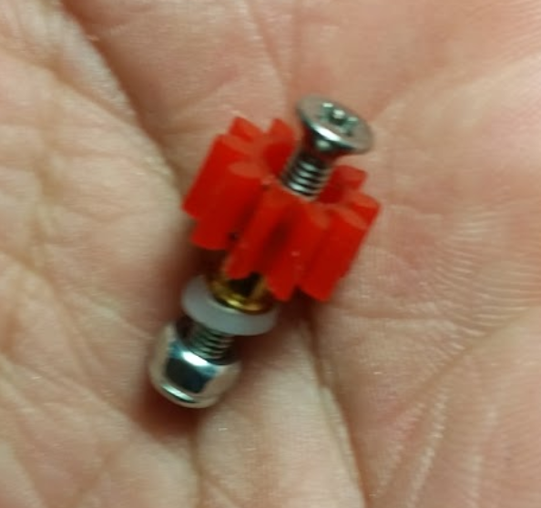
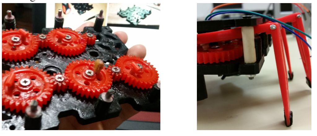
The gears were attached to the chassis of our spider using 16mm flat head machine screws, brass bushings, washers, and nylon lock nuts.

Figure 3: Gear Assembly 

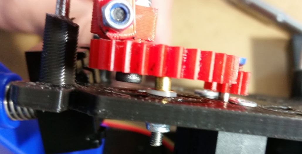
Figure 4: Gear Assembly

From the above figure, we can see that the brass bushing is used to pinch the bearing’s inner ring allowing only the outer ring to rotate.

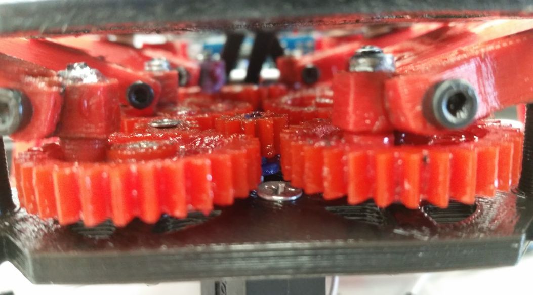
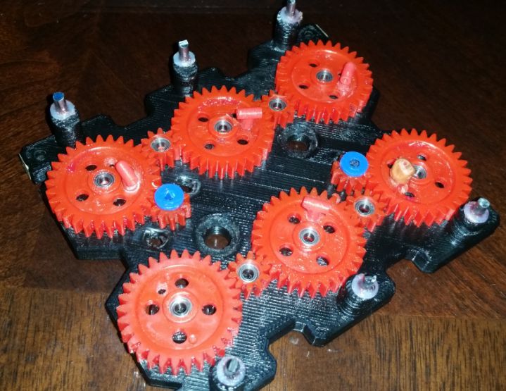
Figure 5: All bearings installed


Modifying our Gear-to-Femur Joints

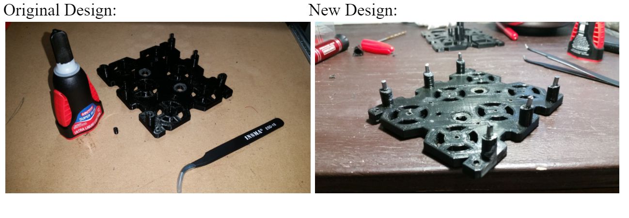
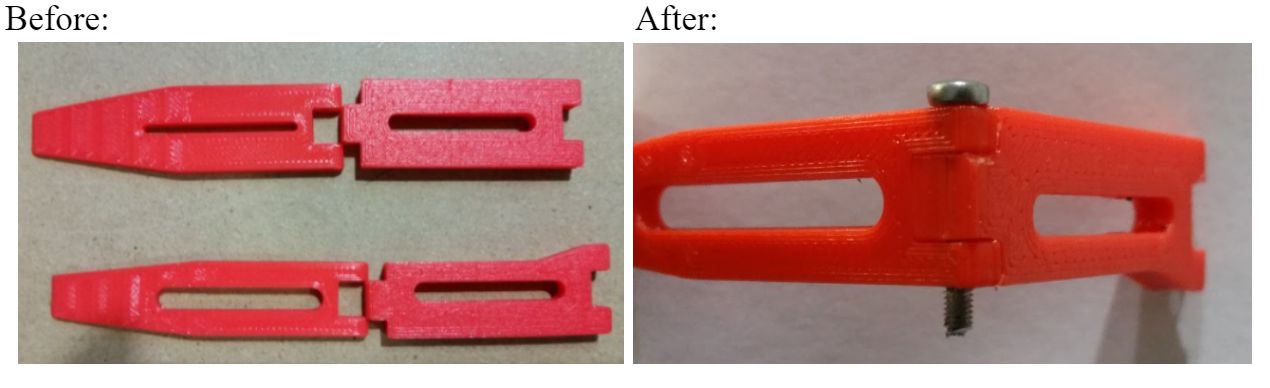
The gear-to-femur joint design in our prototype was very flimsy due to having too much play. This play was coming from using cotter pins and from using screws to hold the joint to the gear. A solution the professor had was to add bushing to the holes and run machine screws and lock nuts to make a more sturdy joint. Manufacturing decided to pursue this solution because implementing this design solution would enables us to control the amount of play required to run our robot at 3.7 V. Nevertheless, implementing this solution requires redesigning the joint as shown below.  

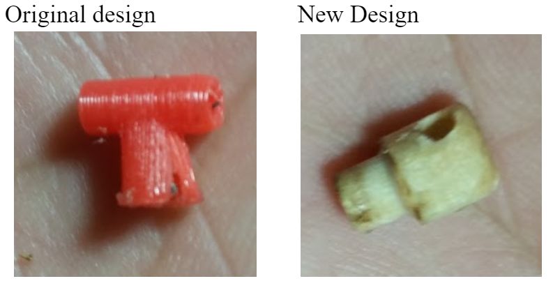
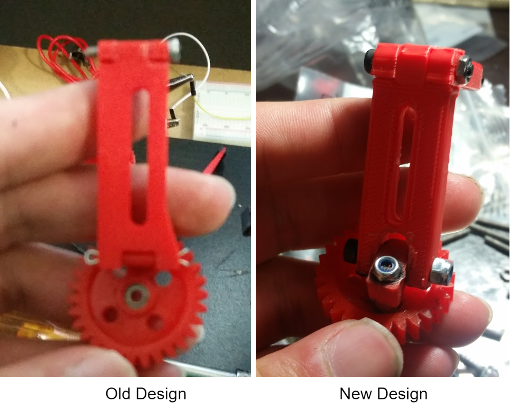
Figure 6: Old vs New Joint Design 

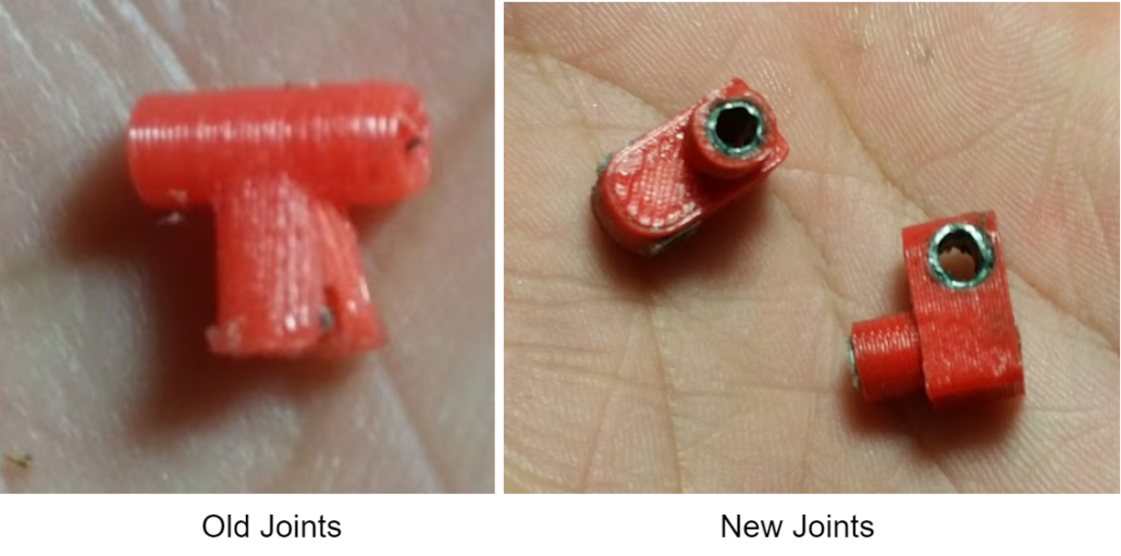
Figure 7: Closer look at old vs new joint 

Dimensions for the new joints can be found by clicking here.

As can be seen above, the new design will have individual holes to provide the 2 degrees of freedom required by our design. Very small aluminum bushings were inserted into these joints. As advised by the professor, Mcmaster carr was the best place to go to find these bushings. However, due to being unable to find the desired specifications for the inner and outer diameter for the bushings (3 mm ID, 4mm OD), time and cost. The manufacturing department decided to make them himself since he has had experience in the past shaping metal. Using an aluminum sheet, the manufacturing engineer was able to make aluminum bushings that would fit into the hole of the joints within a few hours for testing. 

Figure 8: Making Aluminum Bushings 

As shown above, making aluminum bushing is pretty easy, if you have the right tools. First,cut a piece of aluminum to the required perimeter length (C=2*pi*r).  Second, shape the small sheet of aluminum into a tube using an aluminum rod and pliers. Three, cut excess material using wire cutting pliers or a dremel (if you have access to one). Sand and polish the tubes to remove all dents and to smooth the material.


Below is the final assembly of our new design. As can be seen the design looks more sturdy than our old design, because it is. The new joints are definitely much less  flimsy than the old design, and can be adjusted by tuning the cap screws to the amount of play desired for best performance.   

Figure 9: Final Assembly

Prototype Part Adjustments/Modifications (April 05, 2018)

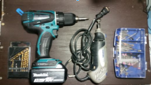
All components mentioned in our 3D model blog post, for Hexy Mk-01, were fabricated using a 3D printer.  Parts that needed to be modified were fixed using a power drill and a Dremel tool for: cutting, grinding, sanding, and shaping the material.

Figure 10: Power tools used 
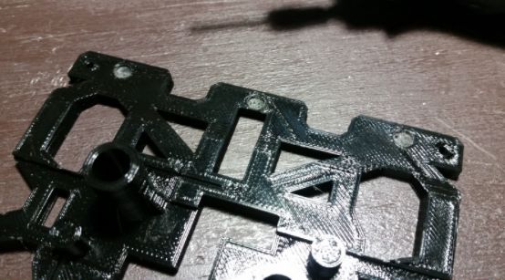
Chassis

Bottom Plate

Removed all shafts

We removed all shafts from the bottom plate design because 3D printed. 3 mm shafts were very thin and fragile.  The manufacturing engineer would have to constantly glue on the broken shaft pieces. A better solution for this is making 3 mm holes at the shaft positions and inserting 3 mm stainless steel rods for the leg guides. Similarly, gear holder shaft were replaced with 3 mm holes and will insert machine screws and nuts to hold the gears down. We also increased diameter of the wire holes by 2 mm using a dremel tool. Therefore, in the Solidworks file revision, all shaft extrusions will be converted to holes.

Figure 11: Replacing all shafts with holes 

Added spacers to the base of all the leg shafts

This was done in order to raise the overall height at which the legs would rise.

Figure 12: Added white spacers to shafts

Made holes for motors on the underside of the bottom plate

3 mm holes for motor boxes on the underside of bottom plate were added. This was done because the thickness of the bottom plate was preventing the motor shafts from having a good contact with the gears they connect too. Future revision of Solidwork files will require reducing the thickness of the bottom plate.  

Figure 13: Adding holes to underside of bottom plate 

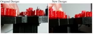
Figure 14: Left – original shaft clearance, Right – new shaft clearance

Top Plate

Modified Resting holes for leg guide shafts

The resting holes for the leg guide shafts were too small, so we had to increase the diameter of them by approximately 1.5 mm using a dremel tool.

Figure 15: Modifying top plate holes

Legs

Femurs

Sanded femur joint to tibia

Due to making the dimensions of the joint between femur and tibia the same size in both ends, mating the femur to the tibia was not possible. Therefore, the femur insert had to be sanded down using a dremel to enable the femur and tibia to mate correctly.

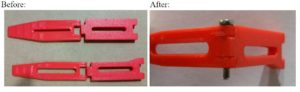
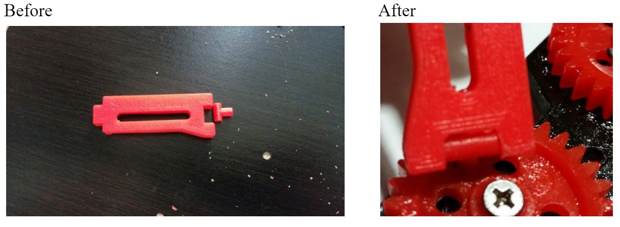
Figure 16: Before and after images of mating leg joint 


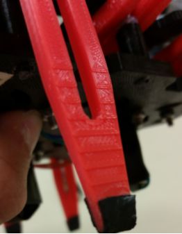
Modified femur-to-gear joint junction

The edges on the underside of femur-to-gear joint junction were rounded. This was done because this end would tend to get stuck on the screw during rotation of the gear. We also increased the diameter of the hole to 2.5 mm in order to easily insert cotter pins

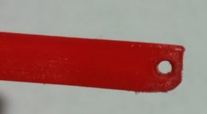
Figure 17: Modified femur edges and hole

Tibias

Adding grip

The tibia designed would bond easily to femurs after femur joint was modified. The only issue discovered was that the current design of having plastic tips would make Hexy susceptible to sliding while walking. Therefore, we decided to glue thin 10 mm x 5 mm x 2 mm pieces of rubber to the tips of the legs to increase the grip Hexy will have while walking.

Figure 18: Adding grip to tips

Femur-to-Gear Joints

Sanded junction between gear joint and femur

The same issue we had with the femur-to-tibia junction came up with the femur to gear joint. The dimensions of both mating points were designed with the same measurements causing them to not fit together as they should. The solution was to sand down the junction between the joint and the femur for better fitment.

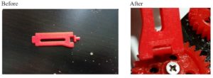
Figure 19: Adjusting gear joints for fitment

Modified Gears

Added 2 mm holes on the gears in order to insert the screw that will hold the femur-to-gear joint in place.

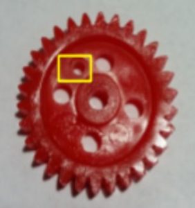
Figure 20: Adding hole to gears 

Testing Alternative gear-to-femur joint solutions

The current joint design was not very reliable. Do to the thin design of the borehole walls (where the screw is to be inserted), the joint would split open when a screw would be inserted. Liquid glue had to be added to the joint to hold it in place. Two solutions proposed by the manufacturing department were to either: redesign the joint and 3D print one with thicker borehole wall, or make them out of more durable materials, such as wood. Below is an image of a wooden joint fabricated by the manufacturing engineer. We will attempt to redesign joints to look like the wooden sample which is thicker. We might even try 3D printing them for easy manufacturing. If 3D printing these joints doesn’t work we will make them out of wood.  

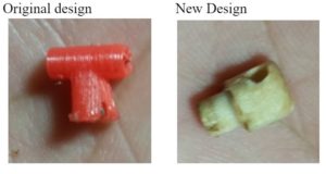
Figure 21: Two types of gear-to-femur joints 

Spacers

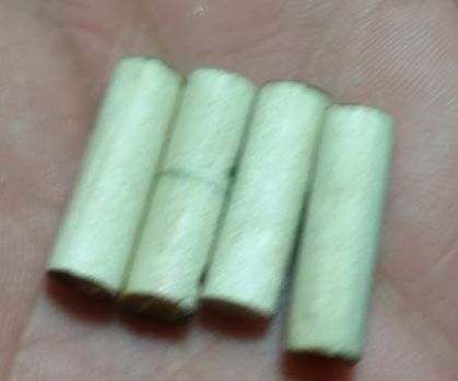
Four 20 mm spacers were fabricated out of wood tubes for this prototype and will be replaced by nylon spacers in a future revision.

Figure 22: Wooden spacers 

Driving Gears

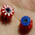
Our plan for making the connection between the 10T driving gears and the motor shaft is to do one of the following:

  1. Insert a bushing to 10T Ajax gears to compensate for the different bore diameter of the Ajax gears and the diameter of the gear shaft.
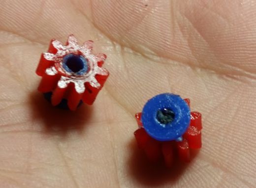
Figure 23: Method 1 
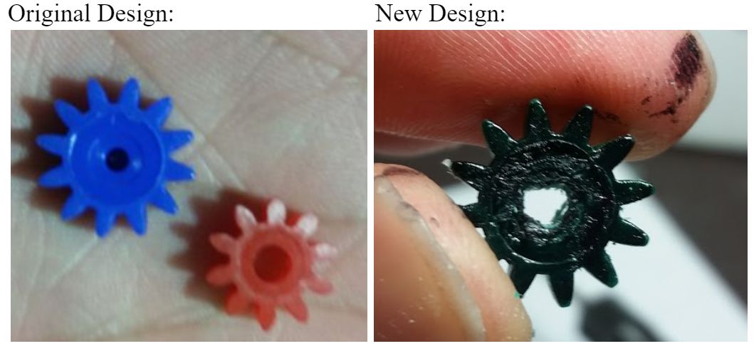
  2. Purchase 10T gears with a smaller bore diameter and shape a D that matches that of the gear motor shaft. This is done to lock the gear to the motor shaft while spinning. Figure 24: Method 2 

Conclusion

Both designs have been built and tested. From the test we saw that both methods work the same and don’t differ in performance when driving the motion of the cam system. We will use method A due to having the same gear color as the rest of the cam system, as well as for providing the least amount of play when inserted to the motor shaft. We will use method B as a backup in case we have issue with method A later in the design.


Spring 2018 3DoT Hexy: Decision on Motor Type Selection

By: Kris Osuna (Electronics and Control Engineer)

Verified by: Eduardo De La Cruz (Project Manager and Manufacturing Engineer)

Approved by: Miguel Garcia (Quality Assurance)

Introduction

The purpose of this blog post is to introduce the different types of motors that are at our disposal. We will compare and contrast each type of motor, and conclude the post with a final decision on which type of motors are best suited for our Spiderbot design.

Brushed DC Motor  

Is used commercially in toys and also in industrial use. Inside are brushes that rub on a copper ring so that current goes through the coils as the motor spins while surrounded by positive and negative magnets.

Pros: Inexpensive and lightweight.

Cons: Very electrically noisy, needs extra circuits and connections for controlling, an difficult programming for small movements.

Figure 1: Brushed DC Motor


Brushless DC Motor

These motors are close to the brush motors except that they don’t make as much noise as them. These are use in fans, drones or multicopters.

Pros: Quiet

Cons: Needs extra connection and circuit to control the motor.

Figure 2: Brushless DC Motor 


Stepper Motors

Is a motor that moves in steps unlike the brushed and unbrushed DC motors. Since it moves in steps it has precision control. It is used in 3D printers, robotics and printers.

Pros: Precise repeatable positions, speed control, great low-speed torque and great ‘holding torque.’

Cons: Low efficiency, needs encoder for reference and needs extra circuit board to use on Arduino.

Figure 3: Stepper Motor


Servo Motors 

Is a motor that uses negative feedback to control motor speed or position. They use very precise motion control. These are the most commonly used in electronics. Used for robotics, animatronics and electronic cars, boats or planes.

Pros: Low cost, variety and simple to control.

Cons: Limited range of motion goes from 0-180 degrees can become jittery if trying to hold a position.

Figure 4: Servo Motors 


Continuous Rotation Servos

Are similar to the normal servo motors except that it has more mobility it can go 360 degrees and go in reverse. It contains a built in H bridge so no extra circuits were needed. Used in robot drive trains.

Pros: Inexpensive, small and easy to control

Cons: Not designed for large loads.

Figure 5: Continuous Rotation Servo Motor


Final Decision

Micro-motors

Figure 6: Micro-motors 

We decided to use a micro brushed motor  for our design. This is due to 3DoT David using the same type of motor. Their motor trade off study shows we will use the 3.7V 50,000 RPM Small Colorless Motor 716. These motors are extremely cheap at $1.95 each compared to $10-20 for servo motors.

Resources

  1. https://learn.adafruit.com/adafruit-motor-selection-guide/dc-motors
  2. https://learn.adafruit.com/adafruit-motor-selection-guide/brushless-dc-motors
  3. https://learn.adafruit.com/adafruit-motor-selection-guide/rc-servos
  4. https://learn.adafruit.com/adafruit-motor-selection-guide/continuous-rotation-servos
  5. https://www.seeedstudio.com/37V-50000RPM-Small-Coreless-Motor-716-p-1884.html
  6. 3DoT David Motor Trade off
  7. https://learn.adafruit.com/adafruit-motor-selection-guide/stepper-motors

Spring 2018 3DoT Hexy: Work Breakdown Structure

By: Eduardo De La Cruz (Project Manager and Manufacturing Engineer)

Approved by: Miguel Garcia (Quality Assurance)

Introduction

Below is the Work Breakdown Structure (WBS) for our project. The diagram is broken down into task each division engineer will be responsible for in the production of the final product. These assignments are based of the task matrix we developed as a class. Engineers can use this diagram as a reference for what they need to do. For a more detailed explanation of what each task consists of, consult the task matrix.

Figure 1: Work Breakdown Structure


Eduardo De La Cruz – Project Manager and Manufacturing Engineer 

Due to having only three members per group, the Manufacturing Engineers of each group was assigned the task of project manager. Therefore Eduardo will be responsible for completing all the manufacturing and managerial task to ensure mission success.

The task shown above are broken down into top level task. All task that fall under each top level task will be the task each engineer will be accountable for. Top level task are organized in the order of priority. Therefore,

Top level task:

As Project Manager Eduardo will have to:

  • Prepare the project planning documentation
  • Prepare all design documentation
  • Project Launch Documentation

As Manufacturing Engineer Eduardo will have to:

  • Create the Mechanical Drawings.
  • PCB layout
  • Design the 3D Models.
  • Manufacture Parts and Assemble final model.

For specific details on what each task contains, see the work breakdown structure chart.


Kris Osuna – Electronics and Control Engineer 

Kris Osuna will be responsible for designing, programming, and for doing all research for the hardware we will be using. His top level task are organized in order of priority:

Top level task:

  • Electronic Design
  • Trade Studies/Research
  • Microcontroller and PCB
  • Programming/Control

For specific details on what each task contains, see the work breakdown structure chart.

Raymundo Lopez Santiago – Mission, System, and Testing

Raymundo Lopez Santiago’s top level task will be to work on the system design, software, and hardware testing.

Top level task:

  • System Design
  • Software (for Arxterra interfacing)
  • System Testing

For specific details on what each task contains, see the work breakdown structure chart.

References

  1. Fall 2017 Goliath preliminary project plan 

Motor-Mock Up

By: Jordan Smallwood (Project Manager)

Approved by: Miguel Garcia (Quality Assurance)


Table of Contents

Introduction

One of the requirements of the Pathfinder is to determine whether a no-load condition is present, we needed to define what that condition is. In order to test the characteristics of our motor a simple experiment was conducted. The idea is that we wanted to control the load to the motor under a constant voltage and extract the current from the Arduino.


Setup

Appropriate connections were made to interface the Arduino to the VHN 5019 motor drivers so that we could read the output voltage from the onboard current sensors. To communicate with the Arduino through MATLAB we needed to install an add-on package called, “MATLAB support package for Arduino Hardware”. This add-on is very simple to use and eliminates the need for uploading code through the Arduino IDE. It allows for direct control of the Arduino through the serial port and MATLAB has predefined functions that allow for this.


Software

Figure 1: Code for Plotting Motor Current Draw

The code is very simple, it is a while loop that compares the current time with the limited time. While in the loop it reads the analog voltage from the current sensor and then stores that value in a vector that has a corresponding time stamp. After this you can apply some smoothing features to the plot such as an n-point moving average so that we don’t see all the discontinuities.


Results

Figure 2: Results from Motor Mock Up


After applying a 25 point moving average this is the result. I applied a resistance to the wheel with my hand about every 5 seconds or so and as you can see, the spikes are where the load was applied. This is very good information for us since we know that the motor under no-load is about 30 mA. In addition, these motor’s have much less current draw than the previous motors on the Pathfinder. In order to get accurate results when applying this to the final mission, we will need to apply an averaging filter to ensure we don’t turn off the motors when they are actually experiencing a load.


References

  1. https://www.mathworks.com/videos/plotting-live-data-of-a-temperature-sensor-using-arduino-and-matlab-121317.html
  2. https://www.mathworks.com/hardware-support/arduino-matlab.html
  3. https://www.pololu.com/product/2502