AT-ST Mass Report

By: Joseph Cho (Mission, Systems, and Testing)

Verified By: Intiser Kabir (Project Manager)

Approved By: Miguel Garcia (Quality Assurance)

Table of Contents

Introduction

This blog post will show the mass of the AT-ST and include the ways that the masses have been initially estimated. All of the parts have been measured for the final mass report.

Mass resource report

Figure 1: Mass Report

Description:

Mass of the AT-ST has been estimated by the given masses on the retailers. The 3D printed parts were estimated by rough calculation shown below. PCB mass was estimated by comparing the size to the 3DoT board size.

All of the parts have been measured on the AT-ST. The total mass came out to be 256.80 grams. There are some parts that have been listed as 0 grams because they have been put together in the body weight.

Measuring the Mass

Figure 2: Scale used to measure the mass

Description:

Ozeri pronto digital scale was used to measure the mass of our components. The scale had to be placed on a leveled surface and calibrated by pressing “TARE” button. The weight of the parts was rounded to the nearest gram. I would recommend a scale that has more accuracy for lower masses.

Theo Jansen Leg Dimensions

Figure 3: Theo Jansen leg concept

Description

With the Theo Jansen leg dimensions, we are going to estimate the volume of each legs to find the mass of the legs. The Theo Jansen legs will have a width of 3.96875 mm and thickness of 3.825mm.

Theo Jansen Leg 3D mechanical drawings (from mechanical drawing blog post)

Figure 4: Theo Jansen Leg 3D mechanical drawing

Body (housing for 3DoT and PCB)

Figure 5: Estimated Body Volume

Calculations

Figure 7: Mass Calculations for supports and Joints

Figure 8: Total Mass for one Leg and Joints

Figure 9: Total Mass Calculation for body (box)

Description:

The legs and body calculations were done by estimating the volume of the 3D printed parts and multiplying their density to them. Since 3D prints do not fill the parts completely with the material, the estimate of the mass will be higher than the actual weight. The mass of the AT-ST 3D printed parts will be around 253 grams for the box and 120 grams for the legs.

Resources

  1. http://www.strandbeest.com/beests_leg.php
  2. http://www.psyclops.com/tools/technotes/materials/density.html
  3. https://docs.google.com/spreadsheets/d/1l4bPs0FaRDSLj46PryDBNb4UZcGDcVGFgoV37JaNrXk/edit?usp=sharing

Goliath Spring 2018 – Mechanical Drawings

By: Daniel Guerrero (M&D Engineer)

Verified By: Ernie Trujillo (Project Manager)

Approved By: Miguel Garcia (Quality Assurance)

Figure 1 – Preliminary sketches for the Goliath Tank.

The reason behind this design was to follow the concept of the spring 2016’s design, to create a box shell of the tank as a preliminary design and attempt to fit all of the equipment inside. I tried to steer away from just a simple box for this design and tried to follow the general shape of the German 302 goliath tank. As for the placement of all the gaps in this design, I was aiming to have it accessible enough to configure all of our equipment into the design. For this first edition, I kept the size to five inches in length by four inches in width and about three inches in height.


Goliath Spring 2018 – Interface Matrix

By: Ryan Nguyen (MST Engineer)

Verified By: Ernie Trujillo (Project Manager)

Approved By: Miguel Garcia (Quality Assurance)

The interface matrix shows how each subsystem of Goliath connects to the ATmega32U4 microcontroller. The top header consists of the sub-systems, the left column has the name and pin number of the ATmega32U4. The matrix maps out how each pin is connected.


From the ATmega32U4, the version 6x 3 dot board specifies 16 pins that students can use for their robots. The first matrix shows the two PCBS of Goliath that will be connected to the three dot board, the top header shield, and the front sensor shield.

Figure 1 – Interface matrix of ATmega32U4

The second matrix shows how the components of the sensor shield will be connected; Goliath uses two UV sensors, as well as a range finder to navigate the maze.

Figure 2 – Interface matrix of front sensor shield

Lastly, Goliath uses a gyrometer, connected to the top PCB, to determine turning in the maze.

Figure 3 – Interface matrix of top header shield

Goliath Spring 2018 – Fritzing Diagram

Written by Milton Ramirez (E&C Engineer)

Verified by Ernie Trujillo (Project Manager)

Approved by Miguel Garcia (Quality Assurance)

Figure 1 – Fritzing Diagram for the Goliath Tank.

Parts

  • Pro Micro
  • Motor driver
  • Gyro
  • Range-finder  
  • Multiplexer
  • Bluetooth
  • Color sensor
  • Battery


Description

This a prototype of how we will connect the parts we are going to use, but some of these parts might not make the final design. In this prototype, our processor will be the pro-micro instead of the 3Dot board, since Professor Hill is still working on the 3dot board. Also, for that same reason, we will have to use a Bluetooth circuit for our prototype since the 3dot has Bluetooth implemented in it. We will probably have to use this configuration for most of our testing since we won’t get the 3dot until later in the semester. Also, we have a motor driver to control our motors. We are also using a multiplexer for our sensor, which is a Gyro sensor and a color sensor. Then we also have a range-finder, which this and the color sensor are floating outside on purpose, because the color sensor goes in the bottom of the Goliath. The range-finder will be somewhere in the front. Also, the specific part number is not included since that will also change for the last design.

References

  1. http://fritzing.org/home/
  2. https://www.sparkfun.com/products/12587


Goliath Spring 2018 – Planning and Scheduling

By: Ernie Trujillo (Project Manager)

Approved By: Miguel Garcia (Quality Assurance)

Table of Contents

Introduction

To achieve mission success for the Goliath Tank, a Gantt Chart was created by the Project Manager; the chart depicts all the pertinent tasks that need to be completed before attempting the mission through the maze. With the Gantt Chart, the Project Manager was able to take the tasks from the Task Matrix and display it in a visual chart that depicts the amount of time that is allotted per task and during what time of the semester this task will be worked on.

Figure 1 – Gantt Chart (1/3), these tasks mainly focus on being prepared for the Preliminary Design Review


Figure 2 – Gantt Chart (2/3), tasks that are pertinent to implementing the hardware to the Goliath.


Figure 3 – Gantt Chart (3/3), tasks that focus on software implementation and final verification of the Goliath.

Broad Layout of Project Schedule

Phase 1 (Research), Weeks 1-5:

  • Look through blog posts from prior semesters on Arxterra website for useful information that the current team can implement.
  • Begin developing level 1 & 2 requirements to meet mission objectives and customer expectations.
  • Begin layout for all tasks required to reach mission success at the end of the 16th

Phase 2 (Preliminary Design Review), Weeks 6 – 8:

  • Achieve a thorough schedule to lay out all tasks required to be complete by the team to bring the project to fruition.
  • Accomplish preliminary tasks: preliminary 3D model, system block diagram, Fritzing diagram, mechanical drawings, resource reports, work and product breakdown structure.

Phase 3 (Rapid Prototyping), Weeks 9 – 12:

  • Design multiple iterations of Goliath Tank to make the final product more efficient.
  • Create a program that will integrate all systems that are in the system block diagram. Also, ensure that the program will have the robot operate in a manner that meets mission objectives.
  • Have E & C Engineer work on creating and finalizing custom PCB.
  • Have MST Engineer work on Arxterra custom command and telemetry (Application side)

Phase 4 (Final Product & Mission Success), Weeks 13 – 16:

  • Finalize Goliath Tank 3D model and ensure that all systems are working properly.
  • Complete Project Video that shows the progression of project and implementation of the Engineering Method.
  • Complete Final Blog Post which displays a comprehensive overview of the Goliath project from start to finish.
  • On the day of the Final, demonstrate that the Goliath can navigate through the maze and meet all the L1 & 2 requirements.

References

  1. https://www.projectlibre.com/
  2. Task Matrix

Goliath Spring 2018 – System Block Diagram

By: Ryan Nguyen (MST Engineer)

Verified By: Ernie Trujillo (Project Manager)

Approved By: Miguel Garcia (Quality Assurance)

System Block Diagram

Figure 1 – System Block Diagram for the Goliath Tank.

The system block diagram illustrates how components of the Goliath communicate and connect with each other; from the control panel that uses Wi-Fi to talk with the mobile app to the wheels and treads. More detailed specific components such as the HM11 Bluetooth model is added, and various parts on the PCB parts are laid out; more items are expected when the E&C engineer completes trade-off studies. The 3DoT board houses a rechargeable battery that powers the motor driver and the Atmega32U4, which in turn powers the PCB. The number of pins is listed to demonstrate a rough idea of how many pins are required and create a rough layout for the interface matrix.

Spring 2018 3DoT Hexy: Booster Shield Layout

By: Kris Osuna (Electronics & Control Engineer)

Verified by: Eduardo De La Cruz (Project Manager and Manufacturing Engineer)

Approved by: Miguel Garcia (Quality Assurance)

Table of Contents

Introduction

3DoT Hexy needs to have a 5V source to power the micro metal gear motors and UV LEDs. We are using a booster to get 5V from a 3.7V battery source. Using the software Eagle CAD and the TI WEBENCH tool a schematic and PCB is being made. The original booster we purchased used a 9-ball grid array. This caused a lot of problems. Placing the chip on the PCB editor showed that it starts with clearance errors. This is due to the balls being so close to each other. With Professor Hill’s advice I approved all clearance errors and moved forward.

Requirements

  • Must have an output voltage of 5V and an output current of 1.1A

Materials

  • Eagle CAD software
  • TI WEBENCH interactive tool

Update 3 (April 19, 2018)

We will no longer be using a booster shield for a variety of reasons. 3DoT Hexy has been improved and can move with the load at 3.7V. We will no longer be using the UV LEDs at 5V instead we will be using IR LEDs at 3.3V.

Update 2 (April 13, 2018)

We changed the booster package to a SMD chip. The PCB board was made with no errors and awaits final approval.

Figure 1: Booster shield with the SMD chip produces no errors.

Update 1 (April 13, 2018)

The Eagle CAD DRC check kept producing errors. Placing polygons on the connecting balls resulted in error. Placing routes at different angles produced errors. Placing a route with the minimum width of 10 provided errors. We are looking at different solutions for this problem.

Figure 2: The TI WEBENCH interactive picture provided the schematic to use and even provided an Eagle CAD schematic file.

We were able to find the dimensions of a blank 3DoT board, as a reference for our PCB design:

Figure 3: Blank 3DoT Board 

Link to

  1. Blank 3DoT PCB

The current PCB still being worked on due to errors, nevertheless, we have provided a preliminary design of our schematic and PCB. The finished schematic and PCB will be uploaded when they are finished.


Figure 4: Booster Shield Schematic 

Figure 5: The dimensions of the blank 3DoT PCB shield were obtained and used for our PCB


Resources

  1. EAGLE Training

Spring 2018 3DoT Hexy: Sensor Shield Layout

By: Kris Osuna (Electronics & Control Engineer)

Verified by: Eduardo De La Cruz (Project Manager and Manufacturing Engineer)

Approved by: Miguel Garcia (Quality Assurance)


Table of Contents

Introduction

This blog contains the sensor shield PCB layout that will be sent out for fabrication. The PCB must contain these parts: I2C multiplex, connection to UV sensors, connection to LEDs connection to ground and power. The UV sensors, LEDs and booster are not going to be directly on the PCB. These items are going to be connected through wires so headers are going to be needed to connect them. Having so many headers provided a unique challenge. The headers take up a lot of space so they must be arranged carefully. I placed all similar headers together to reduce any confusion with silk layer text to clearly identify what sensors go where. It is important to know which sensor is at which header so that the software and hardware can communicate efficiently.

The very first initial draft had many minor issues that first time EAGLE CAD users will encounter. Power and ground routes should have a width of 16 and others have a width 10. I suggest using the polygon tool to create power and ground planes. I did not consider the size and price of the PCB. The first version was very large and very expensive. A helpful tutorial can be found under the resources. I highly suggest working on the schematic and PCB as soon as possible. The PCB will go through many revision before getting a final approval. It is very time consuming and then fabrication takes even longer.

Related Requirements

Level 1 Requirements

  • The robot will need to navigate remotely through a custom-built maze (built by AoSa image), memorize the path it took, start over, and autonomously travel through the path it took.
  • The robot shall avoid collisions if it encounters other robots while navigating through the maze. This involves detecting the robot, retracing steps back, and moving to a room that allows the other robot to have a safe passage.
  • The robot shall use a v6.43 3DoT board.
  • The robot shall demonstrate the capabilities of the 3DoT micro-controller for DIY hobbyists.

Level 2 Requirements

  • The robot shall use a single RCR123A 3.7 V, 650mA rechargeable Li-ion battery to power the 3DoT board, which will power the drivetrain and all attached peripherals.
  • The robot shall use 2 UV sensors connected to a custom PCB.
  • The robot shall use a HC-SR04 ultrasonic sensor to handle robot avoidance.
  • Ultrasonic sensor shall have a range of 0.5-meter radius to detect and respond accordingly to other robots.

Materials

  • Eagle CAD software

Version 4 (April 19, 2018)

Final Sensor Shield Version

Fabian sent me the PCB design back with minor changes and permission to send to fabrication. PCB was sent to Oshpark for fabrication with ‘Super Swift Fab’ option for quicker service. ‘Super Swift Fab’ was chosen because we are running out of time, which is why I suggest starting this process as early as possible.

Figure 1: The final PCB design 

Figure 2: Left: Front of our fabricated PCB, and Right : Back side of our fabricated PCB 


<’h3′ class='av-special-heading-tag ' itemprop="headline" >

Parts:

  • 4-Channel I2C
  • Gyroscope
  • 8-pin header
  • Five 4-pin headers
  • 6-pin header

PCB now contains these parts: 4-channel I2C, gyroscope, connection to UV sensors, an 8-pin header, five 4-pin headers and a 6-pin header. The 8-pin header will connect to the 3DoT board, which will provide power, ground and four digital pins. Three of the 4-pin headers will connect to the UV sensors. A 4-pin header will connect the ultrasonic. The last 4-pin header will connect two controllable LEDs. The 6-pin header will connect to 3 LEDs. All headers are now labeled to reduce confusion. Waiting for approval from Fabian to send to fabrication.

Figure 3: Sensor shield version 3 

Version 2 (April 09, 2018)

Parts:

  • 4-Channel I2C
  • Gyroscope
  • 8-pin header
  • Five 4-pin headers
  • 6-pin header

A gyroscope was added to the design for turns. 5V power was taken out and all power will now come from the 3DoT battery. The 16-Channel I2C is now a 4-Channel I2C to save space and connections. Power and ground planes were added for convenience. The additions of planes reduced a lot of routes and cleaned the design.

Figure 4: Sensor shield version 2 

Version 1 (March 22, 2018)

The current PCB is still being worked on. The current schematic image (link 1) and PCB image (link 2) can be found under the links section. The finished schematic and PCB will be upload when they are finished.

Parts: 

  • 16-Channel I2C
  • 8-pin header
  • Six 4-pin headers
  • 2-pin header
  • 6-pin header

Figure 5: Circuit Schematic 

Figure 6: PCB Layout 

Resources

  1. EAGLE Training


Spring 2018 3DoT Hexy: 3D Model (Preliminary/Revisions/Final)

By: Eduardo De La Cruz (Project Manager and Manufacturing Engineer)

Approved by: Miguel Garcia (Quality Assurance)

Table of Contents

Introduction

This blog post contains detailed explanations for the 3D components generated in Solidworks. This post does not contain any dimensions on how to make them in solidworks. If interested in the dimensions of specific parts please see “Spring 2018 3DoT Hexy: Mechanical Drawings” . Our first iteration which is also our preliminary design will be labeled as Update 1: 3DoT Hexy Mk-1 (Prototype).  Revisions will be made within this blog post, and will appear under the table of content as “Update n” followed by the date updated. 

Related Requirements

Level 1 Requirements

  • The robot will be designed to be a toy for people ages 8+.
  • In order to minimize manufacturing cost, and packaging cost the robot shall be able to be constructed from subassemblies within 10 minutes.
  • The robot shall incorporate 3D printed parts to demonstrate the feasibility of the 3DoT board for 3D printed robots.
  • For quick production of the prototype, the preliminary project shall be restricted to six hours of total printing time with a 2 hours limit for each single print.

Level 2 System Requirements

  • The robot shall use 3D printed chassis and legs. This follows from the project level requirement about using 3D printed parts.

Update 3: Final 3D Model – Hexy Mk-02 (April 29, 2018)

Chassis

Bottom Plate 

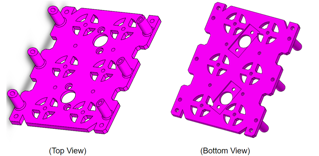
Figure 1: Final Bottom Plate Design 

Design Changes

  • Removed the two wire tubes/wire holes.  This was done due to the inability to route all our wires through the two 8 mm holes (which we could not make bigger due to space). As well as, due to the interference of wires with our hardware because we had to place our hardware in the middle of the top panel too. Alternative methods were found to route our wire to the bottom plate below.
  • Reduced the width of our bottom plate by 12 mm. Since we removed the wire tubes from our bottom panel we were able to make our cam system fit in a smaller space making our design more compact than before.
  • Removed front and back extrusions. These extrusion were removed to provide support for the front sensor enclosure and the rear cable tube, which will be discussed shortly
Top Plate 

Figure 2: Final Top Plate Design 

Design Changes

  • Redesigned extrusions to give easy access to all screw in the bottom plate. In previous revisions of the top plate we saw that not all screws on the bottom plate could be easily reached with a screw driver. Therefore, a solution was to place holes over the screws to eliminate the need of removing the top panel for screw adjustments.
  • The area along the middle was configured to the width of the 3DoT board ~35 mm.
  • Added more space along the front to provide a mounting point for the sensor enclosure.
  • Added decorative fangs to the front to give is the aesthetics of a spider.

Legs

Femurs 

Figure 3: Final Femur Design 

Design Changes

  • Increased size of femur-to-tibia joint to prevent layer splitting in the PLA material.
  • Outer femurs, femur-to-tibia joints where re-designed to have an angled offset to provide more stability/balance while walking. The prototype design was having issue stabilizing its weight as it walked. After reviewing methods to solve this issue we found that the previous Spiderbot (3DoT David) had the same issue and solved it by offsetting the femur-to-gear joint in a similar way as shown below. If interested in seeing their solution see “Spring 2016: 3DoT David Design Evolution”.   This solution enabled us to configure all joints to the same width, therefore all legs will have the same tibia design.
Tibia 

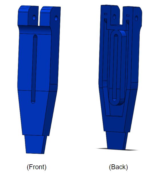
Figure 4: Final Tibia Design 

Design Changes

  • Increased size of the Femur-to-Tibia joint to prevent PLA layer splitting.
  • Redesigned bottom tips to have thin rubber sheets rap around the tips for grip support while walking.  In a similar way as shown in the  Design Modifications Post.

Gear-to-Femurs Joints

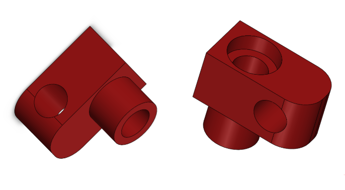
Figure 5: Final Gear-to-Femur Design

Design Changes 

  • Increased Size of the joint and shape to provide exact fitment to femur end.
  • Increased hole size to 3.5 mm. As recommended by the customer, we will be fitting a 3 – .5 OD bushing with ID of 2.5. We will insert a 2.5 mm screw to increase stiffness of the femur-to-gear joint while at the same time allowing the femur to go up and down.

Sensors Enclosure

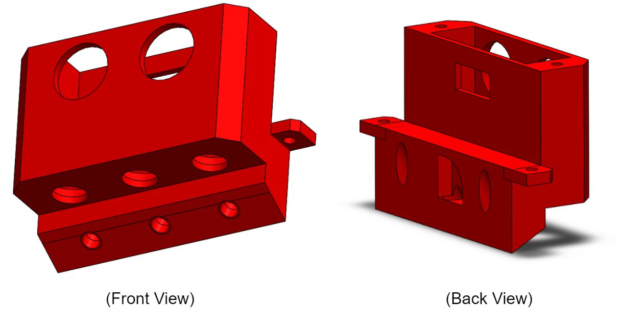
Figure 6: Sensor Enclosure Design

The hardware enclosure will house: One, 3 Pin Ultra Sonic Sensor, Three, Si1145 light sensors, and 3 LEDS. The Ultra sonic and light sensors will be inserted through the top opening, and the LEDs will be inserted through the rear. The bottom hole mounts will connect to the bottom plate and the top hole mounts will connect with the top plate.

Hardware Enclosure

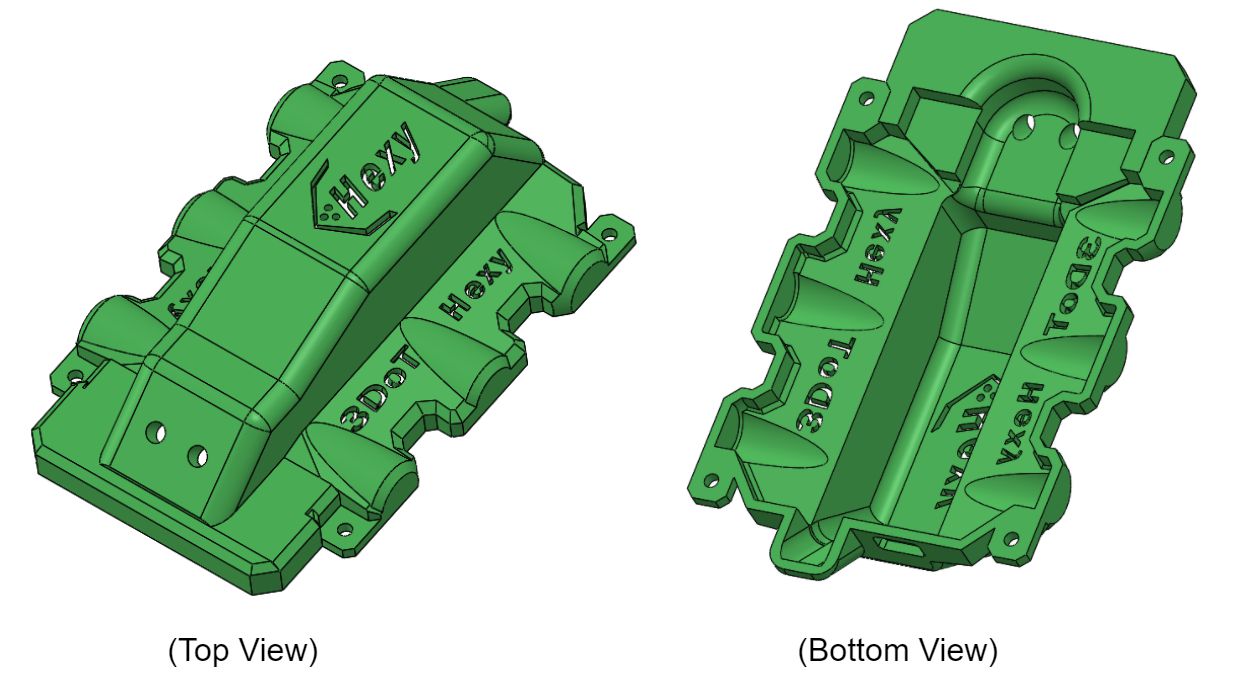
Figure 7: Hardware Enclosure Design 

The top enclosure will give Hexy a better appearance, while at the same time concealing the hardware of our robot. The cover will have have openings for two LEDs that will act as eyes for our robot. There will be unique patterns designed in the top panel for our company logo and product name.

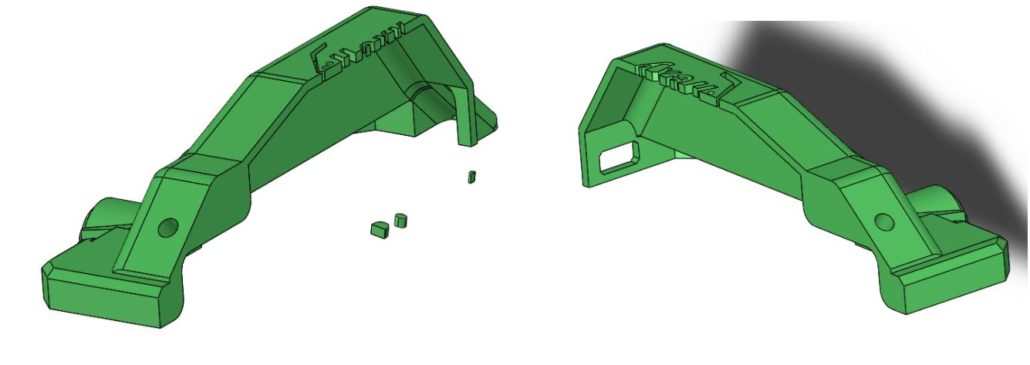
Figure 8: Hardware Enclosure Split in Half 

Do to the size of the cover, we will be splitting it into two parts in order to not exceed the 2 hour limit on single prints.


Figure 9: Wire Tube Design

The wire tube will act as our new method to route wires from the top to the bottom plate. The opening is 15×18 mm and should be big enough to route all a=our wires to the bottom plate without interfering with our design.

Final Assembly

The final assembly is depicted below with the colors we plan on working with.

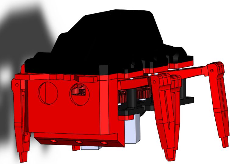
Figure 10: Final Assembly Front View

Figure 11: Final Assembly Rear View 


Figure 12: Final Assembly Side View 

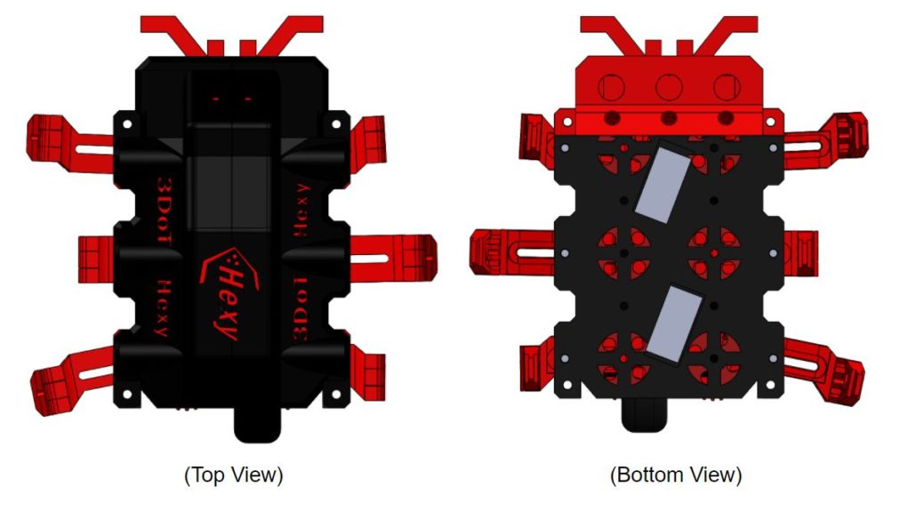
Figure 13: Final Assembly Top and Bottom View 


Update 2 (April 17, 2018)

Top Plate

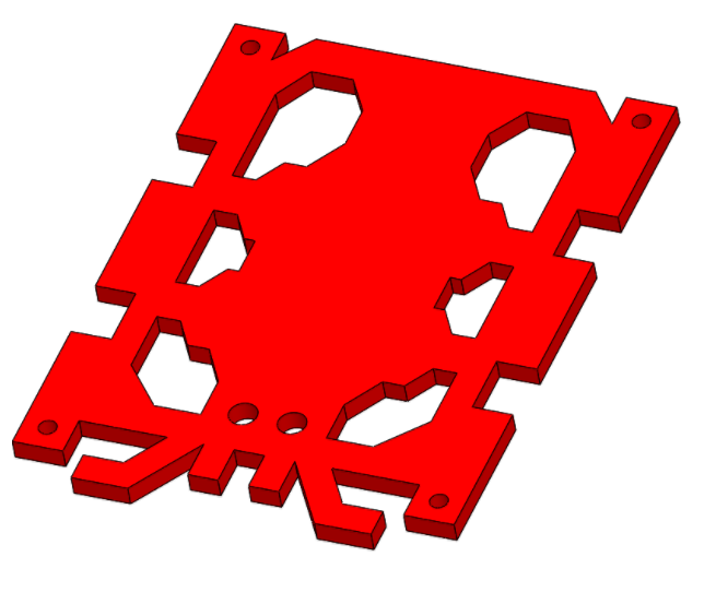
Figure 14: New Top Plate Design 

Design Changes

  • Removed gear popping mechanism from top plate. Will just add spacers to the underside of the top plate to prevent driving gears from popping.
  • Added a face and holes for LEDs which will act as eyes for our spider. As requested by the customer, our Spiderbot needed to incorporate something to the top to make it stand out more and attract the eyes of the consumer.
  • Center width is designed to fit the 3DoT Board which is ~ 35 mm
  • Removed holes for wire routing. New hardware enclosure will include a route for wires. Also, having the wires routing through the center of the top plate would interfere with placement of hardware.

Hardware Enclosure

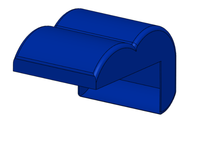
Figure 15: Hardware Enclosure 

The hardware enclosure will conceal our hardware (as most toys typically due) and will have a design similar to that of a spider’s abdomen

New Design Assembly

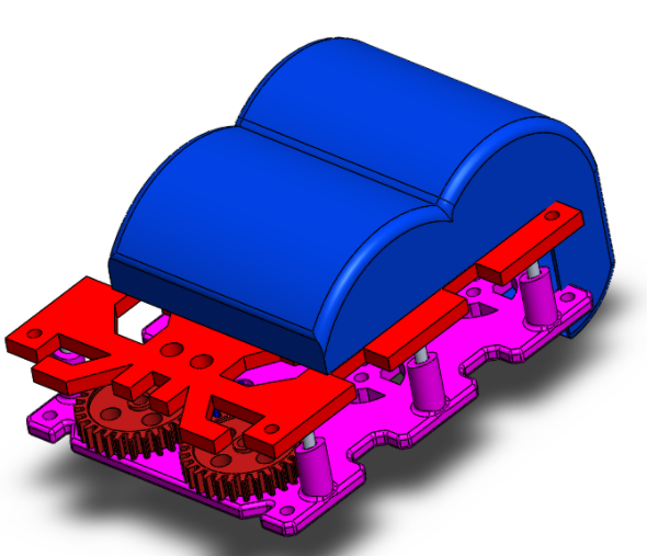
Figure 16: New Design 


Update 1 (April 10, 2018)

After reviewing our design with the professor and by analyzing the quality of Hexy Mk-01 we came up with the following design solutions that will solve the existing problems we have.

Chassis

Bottom Plate

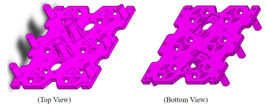
Figure 17: Bottom Plate 

Design Changes: 

  • Removed all shaft extrusions for gears and leg guides. The reason for doing this is that these thin extrusions turned out to be very fragile when 3D printed, as explained in the assembly and fabrication blog post for 3DoT Hexy Mk-01. In multiple occasions, the manufacturing engineer (me) had to glue these thin shafts back in place. A better solution for this is to get rid of all the shafts and leave holes to insert more durable materials. Such as aluminum rods for the leg guide shafts and screws for the gear shafts.
  • For the leg shaft guides, we decided to make 3.5 mm holes and insert 3 mm aluminum rods which will be cut at the desired height.
  • For the gear shafts, we will leave 3.5 mm holes and do one of the following:
    • Use bearings, 3 mm machine screws, and nylon locking nuts to hold gears in place.
    • Use push rivets and gear inserts to hold gears in place.
  • Driving gear holes will be sized to 13 mm (biggest holes shown above) in diameter for easy insert of driving gear with motor attached from the bottom plate (driving gear is 11 mm in diameter).
  • Holes for leg shafts will be 3 mm in diameter (diameter of aluminum rods).
  • Wires tubes designed in the top plate will be shifted to the bottom plate and will have a height of 20 mm.
  •  Corner holes should be 3.5 mm in diameter.
  • Bottom plate thickness reduce by 2 mm to raise level of motors from ground.
  • Add extruded cuts for motor boxes that are 1.5 mm deep, as shown in the bottom view above.
  • Add holes for motor box mounting screws 3 mm in diameter.
Top Plate

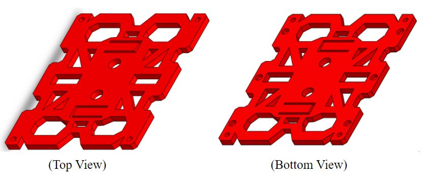
Figure 18: Top Plate

Design Changes: 

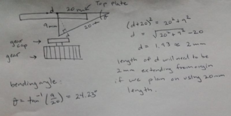
  • Due to higher than expected 3D print times, we will redesign the top plate in order to have it be fabricated using a CNC machine. To do this, we will eliminate all extrusions that were present in 3DoT Hexy Mk-01. We will shift our wire tubes to the bottom plate and use a different technique to prevent the driving gear from popping off. A solution proposed by the manufacturing department is to make a three sided rectangular shaped cut out on the top plate and bend it to a degree such that the rectangle is preventing the driving gear from popping as shown below:

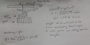
Figure 19: New Design for driving gear, gear capture 

  • Resized corner holes to 3.5 mm.
  • Resized leg guide holes to 5 mm in diameter with 2 mm depth.

Legs

Femurs

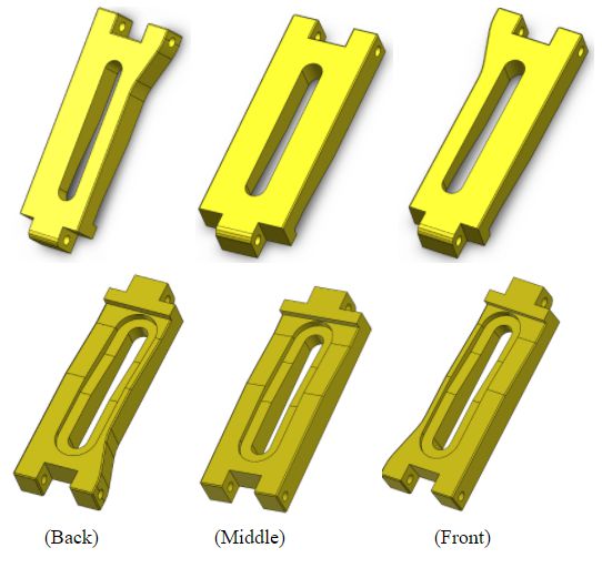
Figure 20: Three Types of Femurs we will use


Design Changes: 

  • Shifted holes that connect to gear joint 2 mm inward to prevent cotter pins from braking through material.
  • Rounded junction where femur-to-gear joint goes to implement new femur-to-gear joint design.
  • Increased depth of extrude cut contour on the underside of femurs by 1 mm in depth.
  • Increased all hole diameters to 2.5 mm.
  • Increased length of tibia-to-femur joint by 2 mm.
  • Rounded edges that tend to come in contact with the screws holding gears in place.
  • Increased femur thickness by 2 mm to give screw holes a better placement and to reduce the probability of inserted screws ripping through material.
Tibias

Figure 21: Two types of tibia

Design Changes: 

To all:

  • Increased tibia thickness by 2 mm to give screw hole a better placement so that when screw is inserted it wont rib through the material.
  • Got rid of narrow tips of legs and replaced them with 4.5 x 3 x 9 mm holes (length/width/depth) in order to add rubber inserts in the tips of the legs.
  • Increased hole size to to 2.5 mm.

Outer Tibia:

  • changed dimensions of center extruded cut to match that of the middle tibia, in order to make all legs have the same profile.

Gear-to-Femur joint

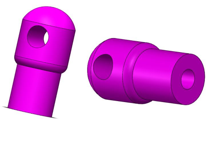
Figure 22: Gear-to-femur joints


Design Changes: 

Note: This design is based of the wooden joints designed during the rapid prototype.

  • New joint will be greater in diameter in the bottom (5 mm) this will provide enough space for 2 mm screw (which is the same as the diameter of the hole) to screw in without splitting open the material.
  • The hole which will connect femur to joint will be 2.5 mm.
  • The top is rounded to provide clearance for femurs when they are raced.
  • The diameter at the bottom is smaller than that of the top due to the smaller clearance available in gears when joints rotate on gears.

Prototype – 3DoT Hexy Mk-01 (March 15, 2018)

Note: Explanations will be a derivative from the explanations given in the preliminary design  document (under the mechanical drawing section). For measurements of each component that will be mentioned read the mechanical drawings document.

Chassis

The chassis of 3DoT Hexy will house: the cam system and legs, mounts for all electronic components, the lifting mechanism, and a safe passage for wires that must connect from the bottom panel to the top panel.

Bottom Plate

Figure 23: Bottom Plate 

This design is based of Sprint 2016’s 3DoT David design. The bottom plate will house the cam system that will mimic 3DoT Davids 3:1 gear ratio design, read “ Spring 2018 3DoT Hexy: Gear Design” document.  Ten shafts with 4mm diameter will be located at 21.125mm from the center axis. We will extrude cut patterns to reduce 3D print times while at the same time giving our design a unique and appealing view to distinguish it from 3DoT David. The lifting guides for the femurs will be angled. This is done in order to provide a smooth transition from ground to peak heights during the legs extension. For the holes found along the center axis: big holes will be used to run wires from top to bottom panel, and smaller holes will be used for driving motor connections. The design will have more holes upon determination of the position of the custom PCB board, battery, and 3DoT board.


Top Plate

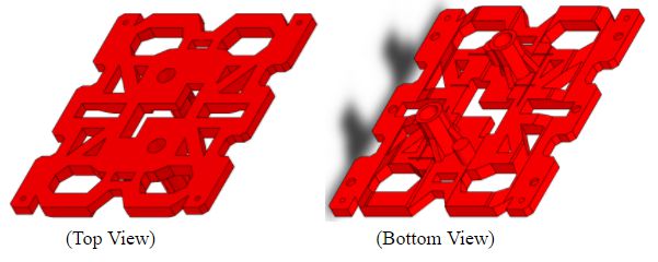
Figure 24: Top Plate 

The top plate will share the same design as the bottom plate to give 3DoT Hexy a better appearance. It will be configured as a universal design, by this we mean that there will be no holes for mounting electronic components, and positioning of components can go wherever desired. Upon determination of all components being used and of their dimensions, the top plate will be reconfigured to accommodate those components in a future revision. For the most part, the top plate will be flat and showing only the extrusions. Looking at the bottom view, the small protruding shafts will be our gear captures (to keep the driving gears from popping) and the two tubes are there for wire management  from top panel to bottom panel. There are holes in each corner for the screw mounts that will hold the top and bottom panel together, and there are three 1 mm deep holes on each side in which the shafts of the lifting guides will sit. We will extrude cut patterns to reduce 3D print times while at the same time giving our design a unique and appealing view to distinguish it from 3DoT David. Lastly, it may be hard to see but the thickness of the plate increases as we move closer to the center of the plate (look at mechanical sketch), this is done to provide support for the femurs when they are in there inner state of motion. If that change in thickness wasn’t there, gravity will push the femurs up making the system unbalanced when walking.

Legs

Femurs

Figure 25: Three Types of Femurs 

As explained in “Spring 2018 3DoT Hexy: Improving 3DoT David Design”, the femurs will house a groove which will provide the transition from ground level to peak height level of the legs.

Tibias

Back/Front

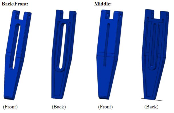
Figure 26: Two types of tibias

The legs will be wider than those of 3DoT David due to the increase width, which is needed to increase contact point of femur-to-tibia joint. The result we can expect from this is increased 3D print times due to larger surface area of tibias. To try to fix this issue we trimmed the width of the tibias by 2mm (from 6mm to 4mm) and decided to shell/hollow out the tibias and cut out excess material by making an opening right down the middle. The legs have a 2mm holes that will align with the 2mm hole of the femur. Thread will be created through this joint and a screw will be placed through femur-to-tibia joint to prevent them from moving. The design of the middle tibia is different from that of back and front tibia, the reason for this is mainly due to aesthetics. Since the middle tibia will support most of the weight, it made sense to make it look stronger than the outer tibia. For this reason, a thinner extrusion and overall wider profile was assigned to the middle tibia. 

Additional Parts

The only other component that will need to be 3D printed will be the T-joints that connect the big gears to the femurs:
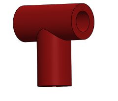
Figure 27: T-joints 

Dimensions for the T-joint are given in the mechanical sketch document

Cam Assembly

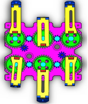
Figure 28: cam assembly generated in Solidworks 

Like 3DoT David’s Design, our model will follow a tripod stability model to keep the robot balanced while walking and to mimic a spider’s movement. The driving gear will be the blue D-shaped bore gears.

Completed Assembly of Hexy Mk-01

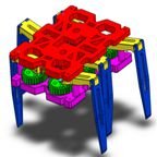
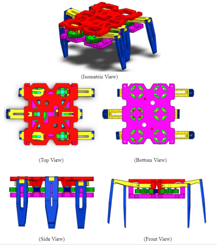
Figure 29: Finished Assembly of 3DoT Hexy Mk-01 for prototyping 

Simulation

Simulation of System Can be found by clicking the bottom link:

https://www.youtube.com/watch?v=DXkc-AGq5vk


Resources

  1. Spring 2018 3DoT Hexy: Mechanical Drawings
  2. Spring 2018 3DoT Hexy: Decision of Movement Mechanism
  3. Spring 2018 3DoT Hexy: Improving 3DoT David Design
  4. Spring 2018 3DoT Hexy: Determining Gear Design
  5. Spring 2018 3DoT Hexy: Preliminary Design Review


Goliath Spring 2018 – Preliminary Budget

By: Ernie Trujillo (Project Manager)

Approved By: Miguel Garcia (Quality Assurance)

Introduction

The customer allotted $200 towards the Goliath Tank project. At this moment, the total expenditure of the project cannot be confirmed as the cost for the PCB and the 3D prints designs are unknown. Also, since the definitions of the maze are not complete at this moment, there is a chance that some sensors will be added to the list while others are removed. About 60% of the budget has been established while the remaining funds will be used for the last few parts that will be needed to complete the Goliath Tank.

Figure 1 – Excel spreadsheet for the components needed for the project.

The spreadsheet provides most of the parts that will be required for mission success. (Will be updated to include all the parts) Included is useful information to the team such as the quantity, cost, and link to the part.

Figure 2 – Totals and general overview of the project budget.

Sources:

  1. https://docs.google.com/spreadsheets/d/1X2e8fMk9zH4d6ugtWx0KzsvcbpDvAjY_uL_h4tcDotE/edit?usp=sharing