By:
Piyush Jain (Project Manager)
Zachary Bruyn & Yasin Khalil (Electronics & Controls)
Natalie Arevalo (Manufacturing)
Melwin Pakpahan (Missions, Systems, & Test)
Program Objective
By: Piyush Jain (Project Manager)
The objective of Project BiPed is to design and manufacture a miniature bipedal robot. The BiPed shall incorporate a Theo Jansen leg design, use a single DC motor and mini servo for walking and turning, and shall use a similar joint mechanism as the 2017 Spring Velociraptor [1].
The model of the BiPed shall use the same principle mechanics as Theo Jansen models, with the design inspired by the 2017 Spring Velociraptor. The difference between the design shall be:
- The head shall be removed and the tail replaced altogether with a different system of allocating the mass to retain a proper center of mass.
- Replace clunky hip design with something more compact which has a smaller turning radius.
Mission Profile
The mission of Project BiPed is to design the BiPed to navigate a predesigned maze [1]. The BiPed shall be able to navigate the maze with user input from the Arxterra App/Control Panel. The BiPed will be able to memorize the user-defined path and will be able to navigate it autonomously. In addition, the BiPed will acknowledge other robots while traversing the maze and avoid collisions.
References:
[1] http://web.csulb.edu/~hill/ee444/2%20The%20Mission.pdf
Requirements and Verifications
Program Level 1 Requirements
By: Piyush Jain (Project Manager)
L1-1: The Biped shall be finished by Wednesday, December 13, 2017 [1]
L1-2: The Biped shall not exceed a budget limit of $250.00
L1-3: The Biped Shall be a toy robot.
Project Level 1 Requirements
By: Piyush Jain (Project Manager)
L1-4: The BiPed shall navigate the maze with user-defined inputs.[2]
L1-5: The BiPed shall memorize said user-defined path and navigate it autonomously.
L1-6: The BiPed shall navigate the maze in seven minutes or less.
L1-7: The BiPed shall navigate the maze without colliding into other robots.
L1-8: The BiPed will be controlled by a 3DoT board.
L1-9: The BiPed will be able to walk on cloth, linoleum, and paper.
L1-10: All electronic components shall be able to be disassembled and reassembled within 20 minutes.[3]
L1-11: All 3D printed robot components shall be printed in less than 6 hours, with no single print session taking longer than 2 hours.[3]
References:
[1] http://web.csulb.edu/gobeach/depts/enrollment/dates/registration.html
[2] http://web.csulb.edu/~hill/ee444/2%20The%20Mission.pdf
[3] http://web.csulb.edu/~hill/ee400d/Project%20and%20Mission%20Objectives.pdf
System/Subsystem: Level 2 Requirements
By: Melwin Pakpahan (Missions, Systems, & Test)
L2-1: Operate using the Arxterra Android/iPhone application. This includes navigating the maze, with and without user input, as well as turning and walking. L1-4
L2-2: Have Bluetooth communication which will sync with the Arxterra Android/iPhone application L1-3
L2-3: Be integrated with all the appropriate libraries to communicate with all electronic devices. L1-8
L2-4: Use a gyroscope/accelerometer to help navigate its way through the maze. L1-4
L2-5: Use a proximity sensor to detect and avoid other robots in the maze. L1-7
L2-6: Design the BiPed’s feet size to be approximately 3″ by 2.5″. L1-3
L2-7: Design the BiPed’s hip size to not exceed 3″. L1-3
L2-8: Design the BiPed’s center of mass shifting system to not exceed 5″ in length and width. L1-3
L2-9: Choose a motor which will provide enough torque to support the weight of the BiPed. L1-6
L2-10: Design the BiPed to be less than 1.5 pounds. L1-6
L2-11: Be powered by one RCR123A Lithium Polymer Battery which will operate for a minimum of 10 minutes before recharge.
L2-13: Utilize one mini servo for turning and one for the mass shifting mechanism. L1-6
L2-14: Be wired in a manner which is professional and shall not interfere with when navigating the maze. L1-6
L2-15: Have two leaf springs on each foot, for stability and flexibility of the feet. [1] L1-9
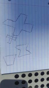
Design Innovation
By: Piyush Jain (Project Manager)
Working from the previous semester’s built BiPed chassis, the team came up with potential problems we might encounter. With respect to the customer’s demands, our main problems were turning the Biped, while maintaining a small turning radius, and the static walk, with the feet in close proximity, all while maintaining a proper balance for the BiPed. We decided we would focus on turning the BiPed as that is the biggest challenge. From our creativity exercise, we surmised different methods of turning including : having a 3″ or less turning gears for the hips, having a joint system similar to humans, and removing the turning gear all together and attaching wheels to legs to drive the BiPed through the maze. The first two methods were thought up during the brainstorming approach, while the last one was thought up during the attritube listing. After going over all our options, we decided to design a turning gear which will be less an 3″ because that will give us the greatest control in how the BiPed turns.
System/Subsystem Design
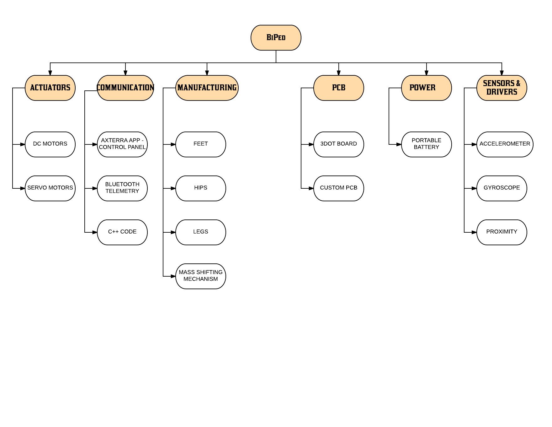
Product Breakdown Structure
By: Piyush Jain ( Project Manager)
Power
The Biped shall be powered by a singular portable CR123A Lithium Polymer Battery. The battery shall power the 3DoT board, 1 DC Motors, 1 Servos, I2C, and the Accelerometer/Gyroscope.
Actuator
The actuators for the BiPed are 1 DC Motors and Servos. The DC Motor will control the leg movement for walking, while the servo will control the turning mechanism.
Communication
The Software for the BiPed will be in C++ and written in Arduino sketch. The code shall control the motor functions and communicate with the Bluetooth module. The module will be controlled via the Arxterra control panel, synched to an Android or iPhone.
Manufacturing
With the chassis prebuilt, we will focus on creating an optimal design for the hip and feet. The hip shall be able to turn with a small turning radius, to fit within the parameters of the maze, while the feet shall be designed to stabilize the structure. In addition, the center-of-mass distribution shall be manufactured as to maintain a center of balance when walking and turning.
PCB
Our design will incorporate two PCB boards. The first will be the 3DoT board, provided by Professor Hill, which will contain the microcontroller and shall control the servos and motors. The second will be the custom PCB board which shall control everything else.
Electronic System Design
System Block Diagram
By: Zachary Bruyn (Electronics & Control)

The Microcontroller has inputs of the battery and input sensors. The battery shall power the BiPed and the Input Sensors; accelerometer/gyroscope and proximity sensor help to navigate the BiPed thru the maze. The Actuators; DC motors and servos help to physically move the BiPed. The communication device includes the Arxterra application, control panel, Android/iPhone, and Bluetooth device give the user the ability to control the BiPed.
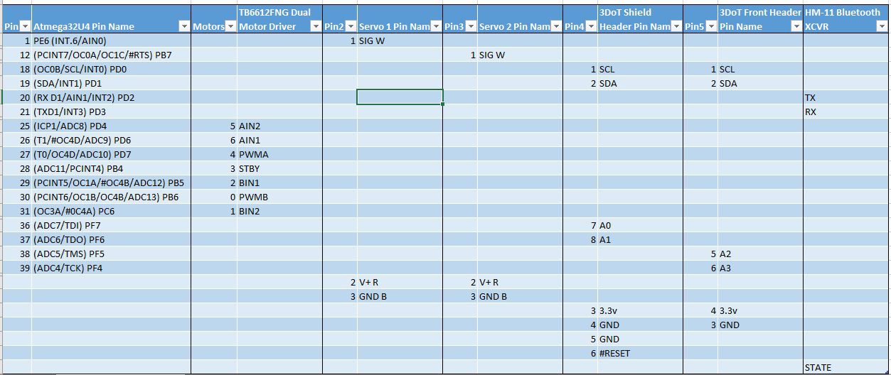
Interface Definition
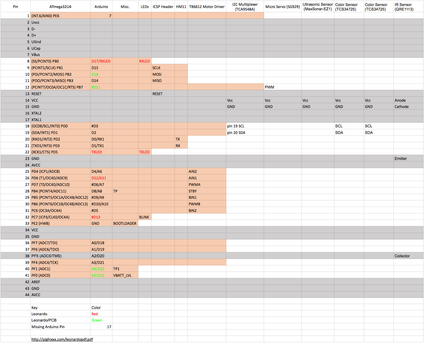
By: Melwin Pakpahan (Mission, Systems, and Test)
The interface definition shown below defines the pins of the ATmega32U4. The microcontroller has a modest selection of programmable pins to configure. In the future, trade-off studies will be conducted to determine which resources would best suit components and how to configure them accordingly [1]


Reference:
[1] https://www.arduino.cc/en/Hacking/PinMapping32u4
Mechanical Design
By: Natalie Arevalo (Manufacturing)
The overall design of this semester’s BiPed project can be broken down into four major sections: feet, legs, hips, and center-of-mass shifting mechanism.
The project as a whole can be seen as an iteration of the Spring 2017 Velociraptor project or modification of the Velociraptor project into a BiPed. As a result, the design of the BiPed will be kept as top-heavy however the head-tail component of the velociraptor will be eliminated. Although the body of the BiPed will be kept heavy to keep its moment of inertia small, the weight will be kept confined to the center-of-mass shifting mechanism as well as the servos and motors. In addition, stability in the legs and feet will be increased by using different materials as that of the previous project for the feet as well as by making the feet bigger to better distribute the weight along to using different springs.
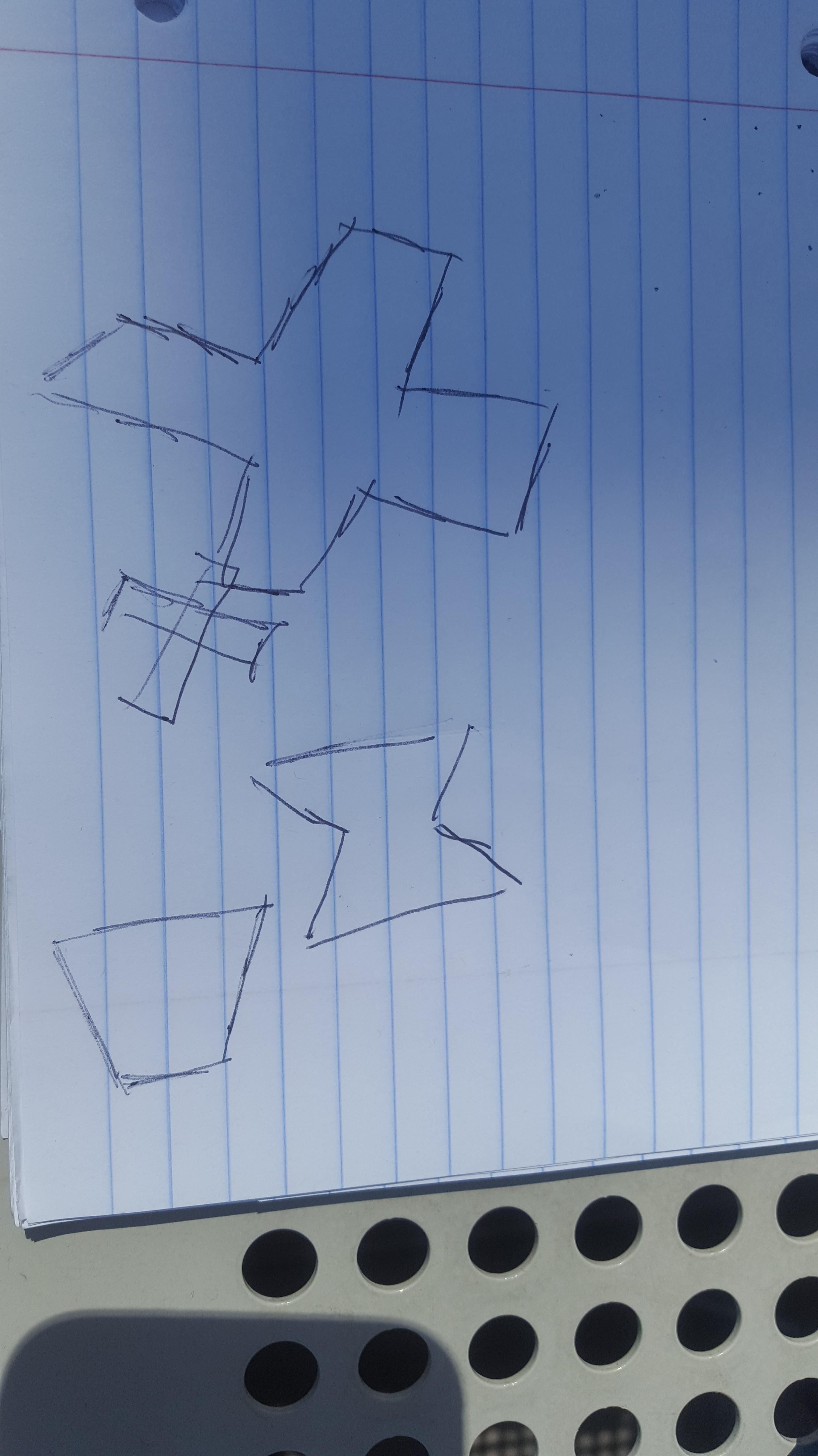
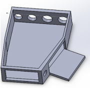
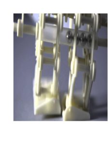
Feet
The size of the feet will be increased so that the weight of the top-heavy robot can be better distributed as it’s walking. Additionally, the shape of the feet was also modified to minimize the amount of material to be used in the manufacturing. Since most of the weight of the robot will be exerted on the corners of the feet, just like how the weight of humans is placed on the toes and heels of the foot, the shape was kept with four major corners.
Back of envelope design
A trade-off study in conjunction with a simulation in SolidWorks will be later conducted to determine which design will work the best for the BiPed. Furthermore, the feet will be incorporated into the BiPed so that they can hinge as the robot takes a step. To increase the stability of the feet and therefore the ankle part of the robot, a leaf spring will be used in place of a traditional spring. The leaf spring will provide the better stability while still maintaining enough flexibility for the foot to flex at every step taken.
Legs
The leg design from the Spring 2017 Velociraptor project will be kept the same. The design used previously is the linkage system found in the Theo Jansen Walking Biped. The linkage system already mimics the kinetics behind walking. Furthermore, the design eliminates the need for taking into account the hinge movement of the knee since the leg rotates at the hip and creates that movement on its own.

Leg Design Model from Wiki [1]
Reference:
[1] https://en.wikipedia.org/wiki/Jansen%27s_linkage#/media/File:Jansen%27s_Linkage.svg
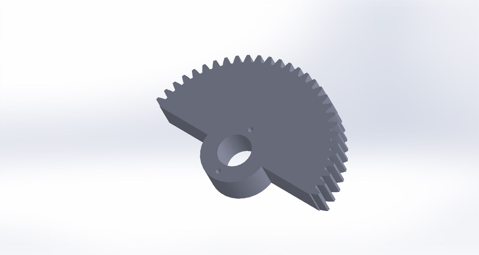
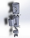
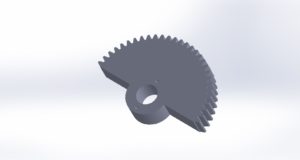
Hips
The hips as a whole are being made smaller in width so as to make them have a tighter look them. This is going to be accomplished by making gears in the hips that allowed the velociraptor to turn have a smaller radius. Additionally, the space between the universal joint and the rotating disk of the hip/leg will be made much smaller. With these two modifications, the hips will be made smaller in diameter which will decrease the distance of rotation during turning as well as decrease the time it takes the robot to turn and therefore navigate the maze. A quick Solidworks model is provided below based on preliminary talks on the optimal design.
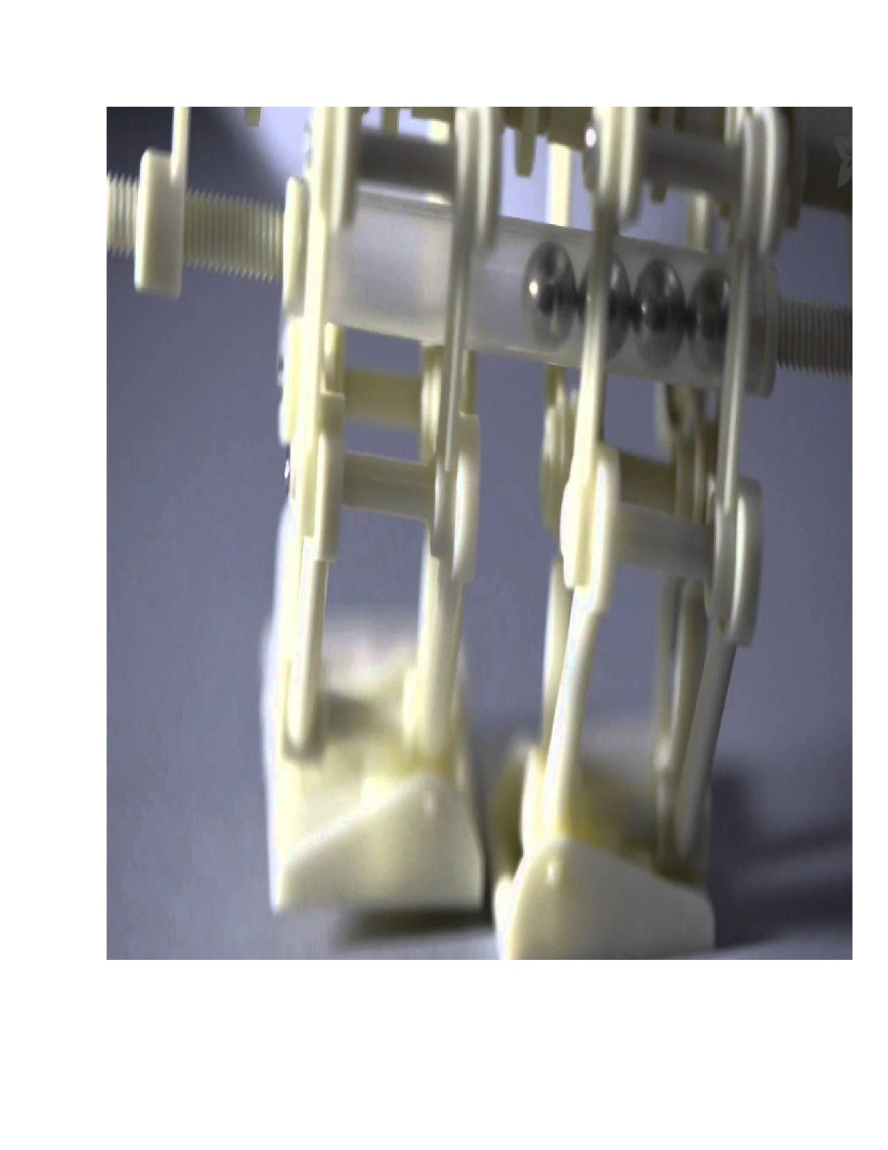
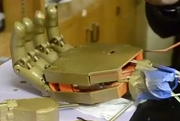
Center-Of-Mass Shifting Mechanism
In order to modify the velociraptor design into a BiPed, the head-tail component was completely eliminated. As a result, a center-of-mass shifting mechanism had to be created in order to shift the center of gravity of the BiPed as it is turning so that the toy will not fall over during this motion. The inspiration for the mechanism came once again from the Theo Jansen Walking Biped. The weight shifting mechanism used in this robot can be seen here:
Essentially, this mechanism would be implemented in an automated version instead of a purely mechanical way. A weight will be placed as part of the body of the robot that will be slowly shifted by a motor to the opposite side of the pivot point of the BiPed as its turning. The modeling and simulation of this mechanism will be done in the future.
Design & Unique Task Description
By: Piyush Jain (Project Manager)
The BiPed shall incorporate a single 3.7v battery which shall power the BiPed through the three maze trials. The battery will be able to be recharged in between the trials. The BiPed shall use one mini servo and one DC motor to help turn and perform a static walk. The turning mechanism shall employ a small turning radius. The static walk shall ensure that the feet are kept in close proximity.
BiPed Tasks
- Conduct trade-off study to choose the optimal DC motor and servo for given parameters. – October 11th
- Create the fritzing diagram to test the breadboard. – October 10th
- From the fritzing diagram create PCB on Eagle CAD. – October 16th
- Using Arduino IDE to create control algorithm for the servo and DC motor – November 29th
- Design Center of Mass part to maintain balance during walking, turning and stopping. – October 29th
- Design lightweight and efficient models for the legs and hip. – October 15th
- Configure proximity sensor to detect other robots while traversing the maze. – October 6th
- Create Interface Diagram which is compatible with both 3DoT chassis and BiPed. – October 11th
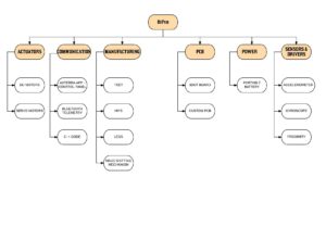
Work BreakDown Structure
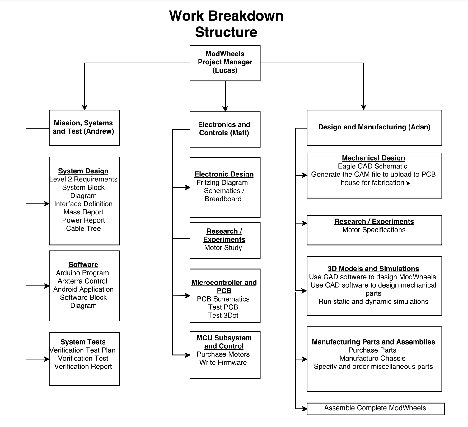
By: Piyush Jain ( Project Manager)
The Work Breakdown Structure displays in an easy to read manner for the tasks which need to be completed by the respected division engineers. It details the kind of work which has to be done, moving forward, in order to have a successful BiPed by December 13, 2017. The tasks were derived from the Lv 1 requirements agreed upon by the customer.

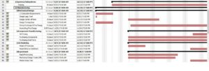
Project Schedule
By: Piyush Jain (Project Manager)
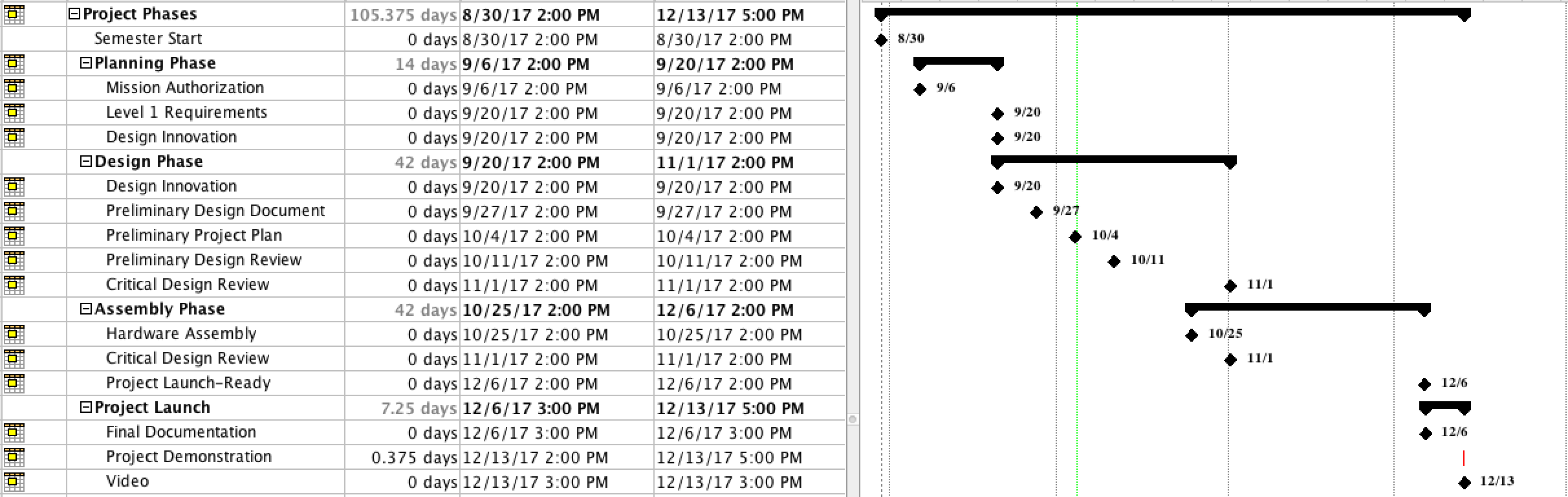
The Project Schedule details the project timeline from a Top-Level/Subsystem Level perspective. The Top Level consists of four main sections; Planning Phase, Design Phase, Assembly Phase, and Project Launch. These four sections help to guide the project towards mission success by breaking the work down into realizable goals.
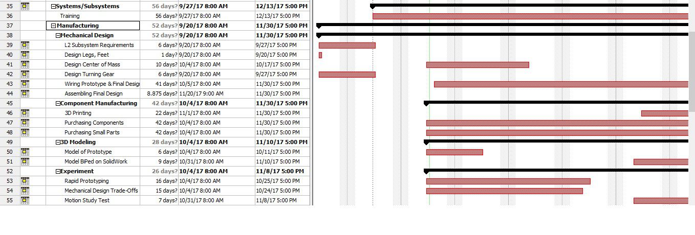
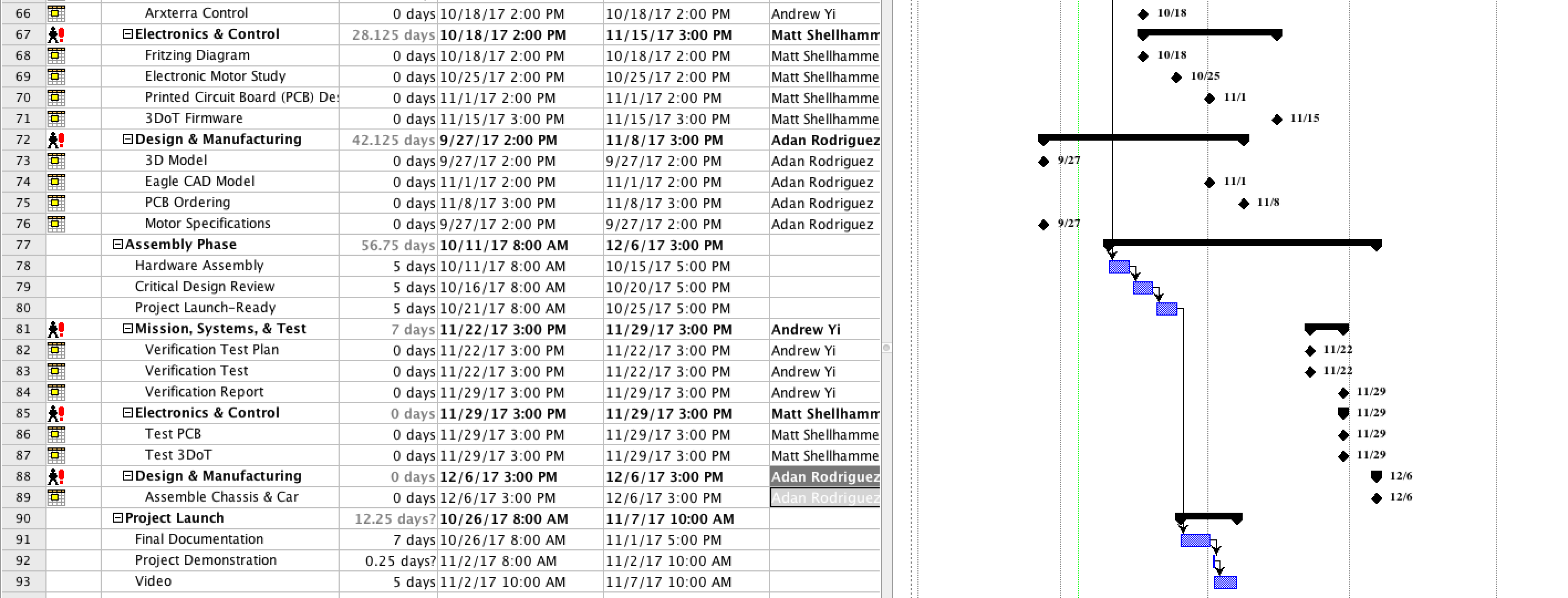
The System/Subsystem Level was designed to complement the Work BreakDown Structure. It details the specific work which needs to be done by each engineer in their specific division. It allots specific time to each task such that the project will be completed by December 13, 2017. It is broken down into the Manufacturing, MST, and E&C division.
Top Level Schedule

System/Subsystem Level Tasks


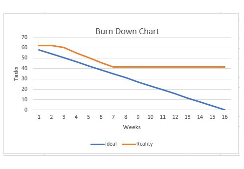
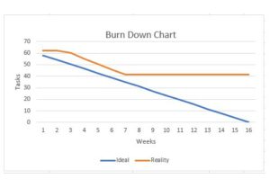
Burn Down
By: Piyush Jain (Project Manager)
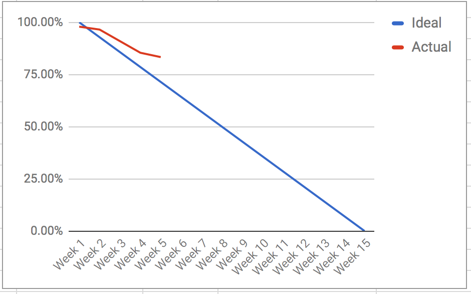
The Burn Down Schedule shows the amount of work needed to be completed in order for the mission to be a success. The blue linear line shows the ideal schedule for the amount of work per week. The orange line indicates the actual work to be done. As shown, the work increases in loads as the semester progresses.
System Resource Reports
By: Melwin Pakpahan (Missions, Systems, & Test)
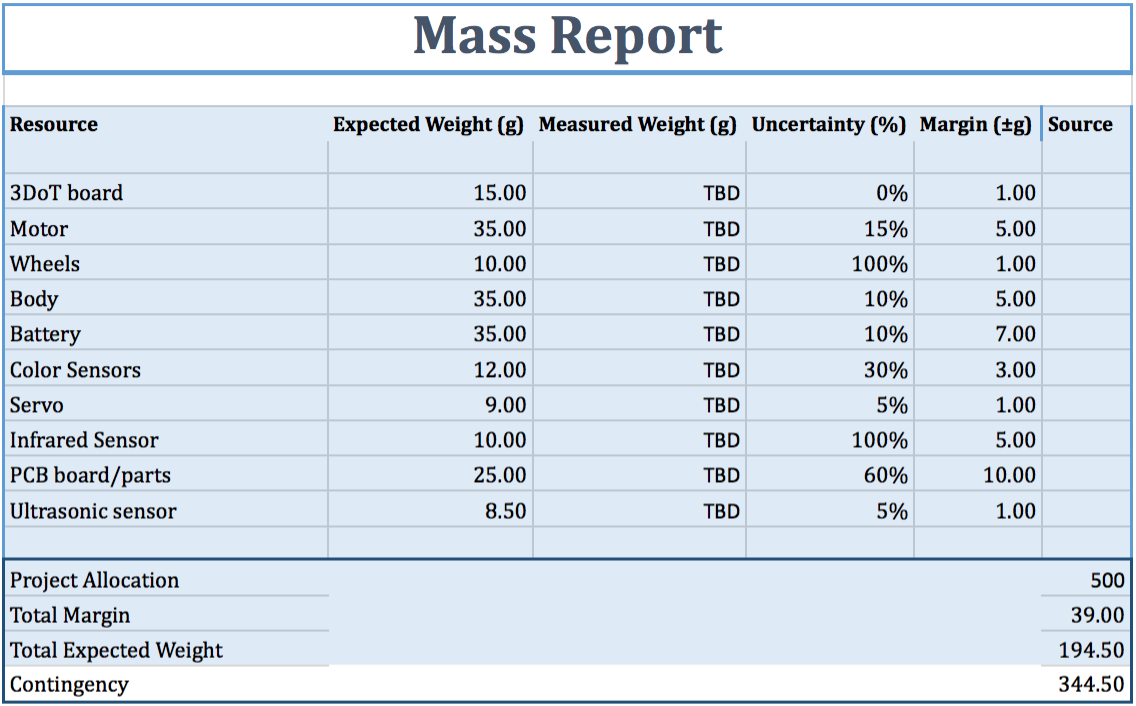
The Lv 2 requirement for the BiPed is to be under 850 grams or roughly 1.5 pounds. This was selected so the BiPed would be able to traverse the maze in a timely manner. A rough mass report was generated to guide us to hit our Lv 2 requirement. According to this report, we are well under the 850 grams. Our biggest item of uncertainty is the frame of the BiPed. It is estimated to come in at 300 grams, which is 200 grams less than the previous semesters’ design.

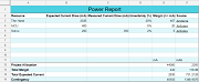
A preliminary power report is provided below. The power report is missing much of the Electronic & Control engineering work because we had many problems with the engineer. By October 25th, 2017 we shall have an updated power report.

Project Cost Estimate
By: Piyush Jain (Project Manager)
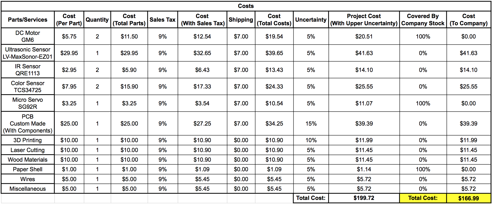
The main program requirement for this BiPed is that it shall not exceed $250.00. A project budget cost was formulated with this requirement in mind. As seen by the image below, we are well below the limit of $250.00. We are able to reduce the cost of this project by obtaining several times from Hill, including the DC motor and mini servo. Also, the sensors decided will be of low cost and optimal performance. The main cost of the project will be the frame of the BiPed because we decided to incorporate a more compact, yet sturdy design. The item of most concern is the custom PCB. Even with a $10 estimate, based on a quick research, we will need to conduct a more in-depth research as to which companies can provide us a high quality, low-cost single board.