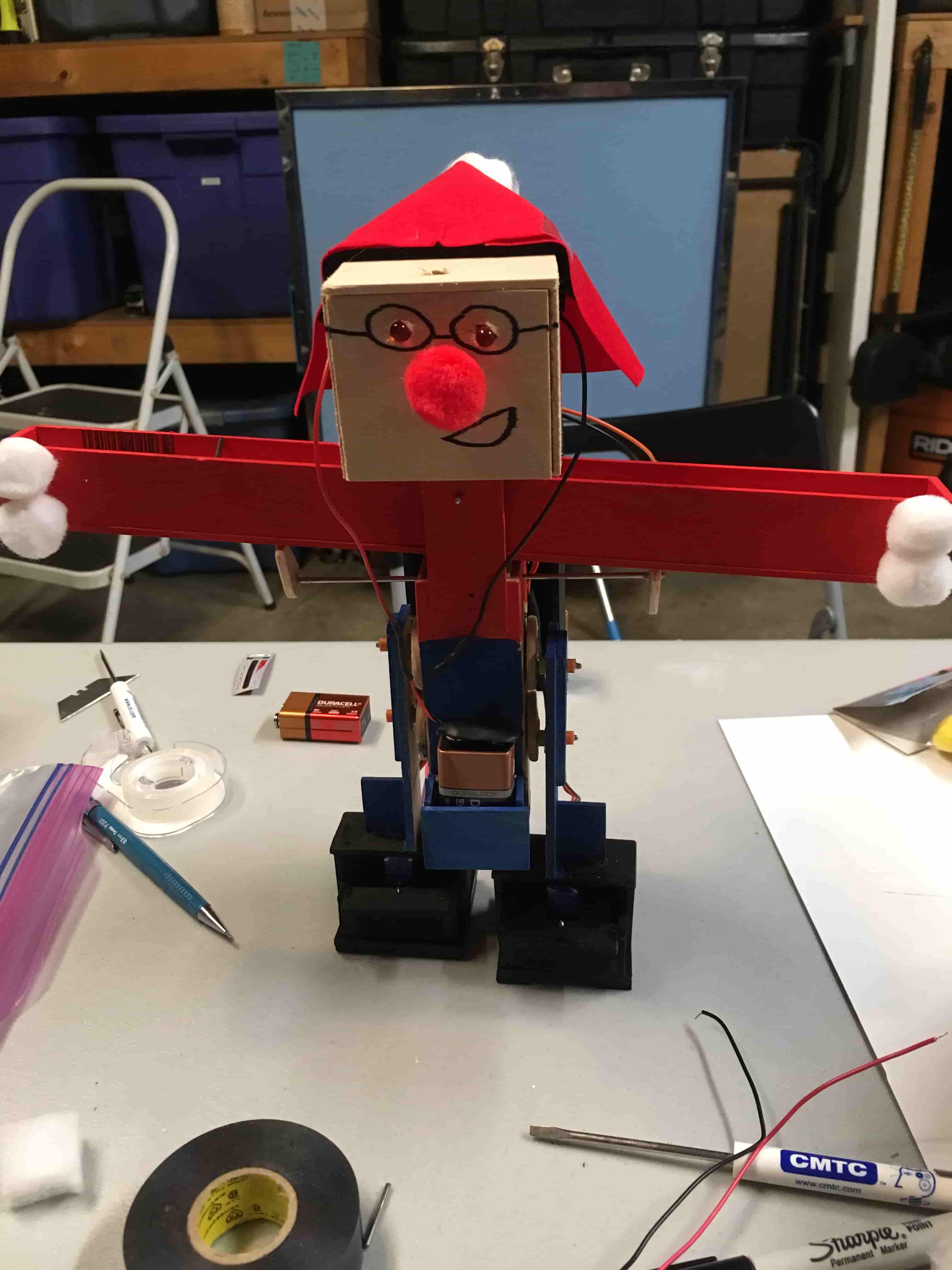
By Martin Diaz (Project Manager)
Edgardo Villalobos (Solar – Design and Manufacturing Engineer)
Anthony Dunigan (Chassis – Design and Manufacturing Engineer)
Renpeng Zhang (Electronics and Control Engineer)
Abdullah Albelbisi (Missions, Systems, and Test Engineer)
Executive Summary
By Martin Diaz (Project Manager)
Program Objective
1. Articulating custom solar panels which are able to track the sun and enter/exit a cocoon state. The panels will be modular allowing the remote identification (telemetry) and astronaut replacement of a broken module. Additional telemetry requirements include providing information on articulation angles, panel voltages, charging current, and battery fuel level. A cocoon state shall be used during simulated launch, dust storms, and operation over steep terrain.
2. Form factor of the solar panels will be identical to the panels on the Spirit and Opportunity Mars rovers. Sizing of the panels will be consistent with the existing chassis and meeting the form factor of the Mars rovers. Specifically, the size of the panels relative to the size of the chassis will be identical to the mars rovers (scaled model).
3. Electronic slip differential 6-wheel Drive for turning and traversal of rough terrain, specifically, the outside and inside wheels will turn at different speeds while turning, plus wheels under no load conditions will stops spinning.
4. Demonstration of GPS navigation mode with obstacle avoidance (articulating LIDAR sensor)
5. The Mission Objective is to traverse the same course defined for the Fall ’16 Pathfinder.
6. Based on the fixed size of the articulating solar panels, efficiency, sun’s path during time of mission, and the mission objective, the project will propose charge time and batteries for the rover. Margins must be identified.
7. No modification to the pathfinder rover shall preclude future High Desert operations (High temperature materials with cooling system as needed). a. Wheels b. Pan/Tilt platform c. AC Unit
Mission Profile
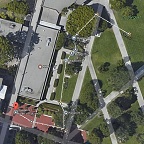
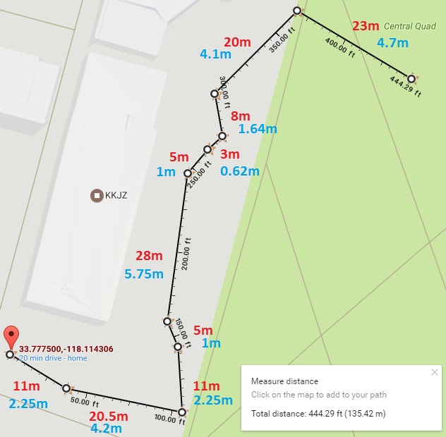
The S’17 Pathfinder will commence it’s Mission by first exiting a “cocoon state” in front of CSULB’s library, then traversing .09 miles to it’s destination charging station. To reach it, the Pathfinder will need to traverse up and down a set of 3 steps. GPS Navigation mode will use 11 predefined checkpoints including start and finish L-L coordinates. Along the way, the Pathfinder will operate in articulation mode, in which the solar panels will track the sun and provide current telemetry of each of it’s 36 cells to a sync’d Arxterra App user within Bluetooth range.
Key Features
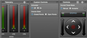
Custom Arxterra Control Panel
- Buttons for opening and closing panels
- Buttons for entering and exiting panel articulation mode
- Meters that show each solar cells output voltage
Proper Rocker Bogie Suspension System
- Obstacle Climbing
- Keeps all wheels in contact with ground in uneven terrain
Cocooning and Articulating Solar Panels
- Solar panels can fold up and down by use of stepper motors and worm gear.
- Solar panels will move up and down to find a better position for increase sunlight.
Solar Cell Telemetry
- Solar Cell Current Telemetry that can be viewed through Arxterra control panel.
Pan and Tilt system for lidar sensors
Electronic Slip Differential
- Inside and Outside wheels will spin at different speeds
- Any tires under no load will stop spinning
Autonomous GPS navigation and Obstacle Avoidance
- In autonomous mode the pathfinder will travel to the next coordinate and avoid obstacles along the way.
Rotary encoders to measure each wheel rpm
- Wheel rpm will be monitored and used in electronic slip differential program.
Level 1 Requirements
- L1.1 Pathfinder shall travel a .09 miles course. Course includes going up a set of 3 stairs at 70 degree inclination and down a set of 3 stairs with a downward slope of 70 degree.
- L1.2 Pathfinder shall launch from cocoon state. Solar panels folded upward at 85 degrees from base.
- L1.3 Pahtfinder shall allow user to manually execute “enter cocoon state” program module via arxterra App to enter into cocoon state at any time.
- L1.4 Pathfinder shall all user to manually execute “exit cocoon state” program module via Arxterra app to exit cocoon state at any time. 85 to 210 angle.
- L1.5 Pathfinder shall allow user to execute “articulate state” program module which is available after the pathfinder has completed the “exit cocoon state” sequence in order to articulate the solar cells directly at the sun limited to the full bend of each wing, which is between 210 and 85 degrees relative to the solar panel base. articulate state is based on an “articulate state” program module which precisely actuates each wing’s stepper motor module’s parameters which include time of day, GPS location, orientation, and local sun trajectory.
- L1.6 Pathfinder shall provide updates of solar panel articulation angles which come from the ‘articulate state” program module.
- L1.7 Pathfinder will provide solar panel voltages and charging current by capturing each modular panels electrical output separately.
- L1.8 Two side panels, a butt panel, and a base panel shall be modularly encapsulated and wired.
- L1.9 From factor of the solar panels will be identical to the panels on the spirit and opportunity.
- L1.10 Electronic slip differential 6 wheel drive shall be implemented by an “ESD” program module.
- L1.11 Wheels that are not in contact with terrain shall be actuated by “ESD” program module to stop spinning by using currents that match free spinning wheel characteristics as inputs.
- L1.12 Pathfinder shall demonstarte obstacle avoidacne during course traversal by articulating 2 lidar sensors via pan and tilt system. The lidar sensors will provide input and be controlled by the waypoint navigation program module used during the fall 16 semester
- L1.13 Pathfinder will utilize “waypoint navigation” program module for autonomous GPS navigation
- L1.14 Rocker bogie system shall be improved by closely modeling the suspension mechanics behind the mars exploration rovers, curiosity and spirit.
- L1.15 Pathfinder will not hinder future use of pathfinder in high desert condition by modification of wheels, pan/tilt platform, and AC unit.
- Pathfinder will be ready to demonstrate mission profile and project objectives by may 12th, 2017
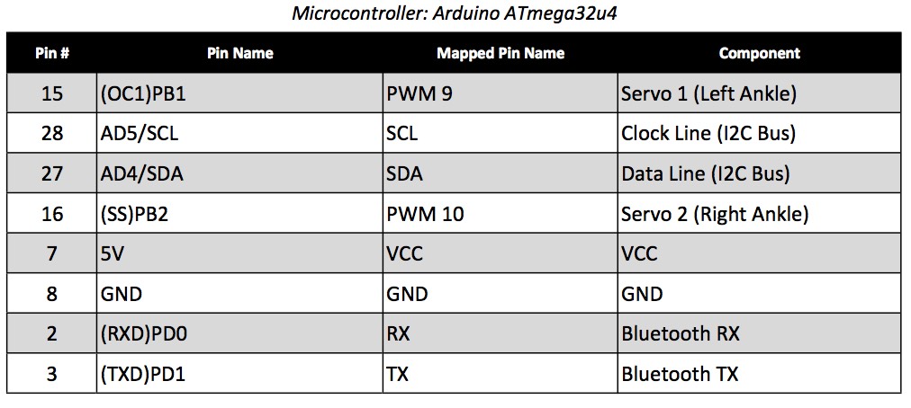
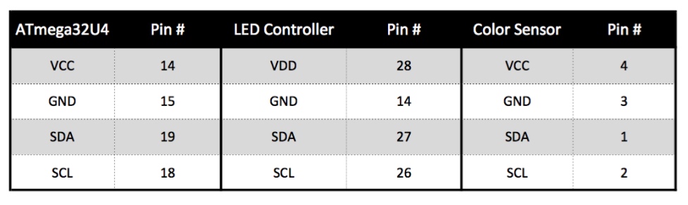
System Design
By Abdullah Albelbisi (Missions, Systems, and Test Engineer)
System Block Diagram
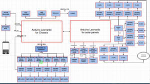
Mission Command and Control
We have used Axterra app to develop a custom command to control ( “Cocoon state”, articulate state”, telemetry)
“Cocoon State” : is a state where we can control the panels to either close or open. The initial benefit from cocooning is to prevent the solars from harm causing by natural effect. We control it
by pressing either “cocoon on” or “cocoon off” on the Axterra app.
“Articulate State” : is a state to allow the solar panels to follow the most dense direction of light to produce power and charge the battery. It can be controlled by pressing either “on” or “off” on the Axterra app.
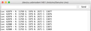
“Telemetry” : 12 custom telemetries have been assigned to address a visual amount of energy is being produced by every 3 solar cells.
Experimental Results
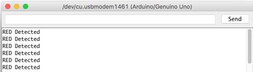
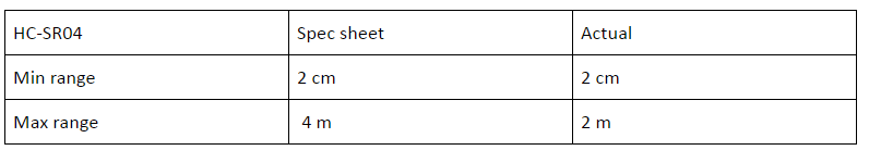
HC-Sro4 Ultrasonic Sensor Test
Wheel Forces Calculations
Solar Current Sensor Experiment
Stepper Motor Control
Solar Panel Voltage Calculations
Encapsulation Trade Off Study
Solar Manufacturing
By Edgardo Villalobos (Solar – Design and Manufacturing Engineer)
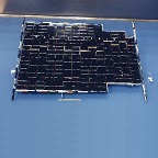
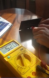
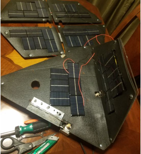
As a requirement, the Pathfinder was to have a solar panel in the shape of the solar panels on the Spirit and Opportunity Rovers that would charge the 12V 7Ah battery onboard the Pathfinder. The wings on the solar panel needed to be able to open and close to a cocoon state and also articulate to the sun. Another requirement on the solar panel was to obtain the voltage differential from each of the solar cells to make it easier to pinpoint the location of the non-functioning cell.

The previous semester’s solar panel group had made the wings out of aluminum, which I found to be a little too heavy for the worm gear mechanism used to make the wings open and close. I replaced the aluminum wings with plexiglass in order to lighten the load, which I now know was a mistake as the plexiglass was not strong enough and will not withstand the heavy heat.
The solar panel consisted of 36 6V 100mA encapsulated solar cells that were arranged in series and parallel in order to achieve the right amount of voltage and current to charge the battery in a timely manner. The rule of thumb with solar panels is that the voltage required to charge the battery needs to be one and a half times bigger than the voltage of the battery in order to stay consistent. The cells were arranged to achieve 18 volts. Each panel consisted of two rows in parallel and three cells in series in each row, theoretically making a total of 18V 200mA. The whole solar panel theoretically achieved 18V 1.2A. The solar cell array was then attached to the first two terminals of the solar charger that was placed on the Pathfinder.

In order to fix the worm gear issue, a box with ball bearings could be made to hold the worm gear and spur gear together for a tighter grip. Another solution is to make the size of the gears larger. The problem here is that the weight of the wings was causing the hinge to bend away from the worm gear. In order to get the ball bearing box to work, the placement of the wings and hinges would also need to change. The gears could also use a little oil/grease for easy movement.
Another problem with the wings is that they don’t fully close onto themselves as the material on top of the wings gets in the way. A solution to this could be the use of L-hinges. Although the L-hinges aren’t the nicest to look at, they do provide room for overlap.

In conclusion, I was unable to get the solar panels articulating/cocooning mechanism to function correctly. With the little changes I described will make it work.
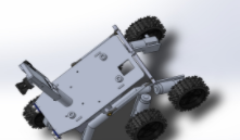
Chassis Manufacturing
By Anthony Dunigan (Chassis – Design and Manufacturing Engineer)
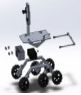
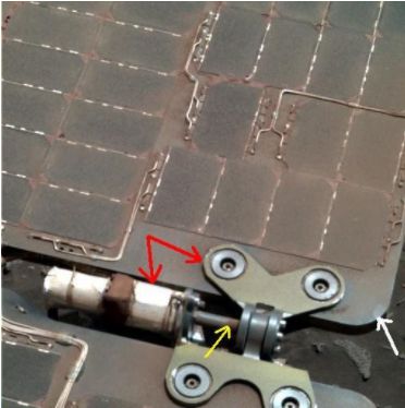
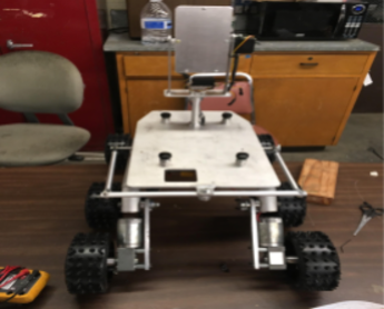
The new chassis design was based on the fulfilling the requirement of improving the rocker bogie design by closely modeling the suspension behind the Mars Exploration Rover. The design is a modified version of the MER Curiosity, Curiosity’s differential bar is located on top of the rover since it did not have any solar panels. But our project has the solar panel so the model that was design last semester place the bar in the rear of the rover. The differential bar allows one leg to rotate down and push the opposite leg down. This will the allow for all 6 wheels to remain on the surface. The issue with the previous design was that the rover could not maintain all 6 wheels when going over an obstacle that is greater than the diameter of the wheel. Mars Exploration Rovers should be allowed to traverse over obstacles that are approximately 1.5 times to 2 times the diameter of the wheel. The previous design could barely traverse over obstacles its own wheel diameter. The new design to improve the rocker bogie was increase the length of the bar to allow more room for the legs to go up and down freely without hitting the chassis.
The new bar was increased from 9.75 inches to 12.125 inches to accomplish this.

Another issue with the previous design was the bogie pivot (the pivot where the two legs are attached to) were not allowed to move freely. The issue was fixed by by using 2 ball bearing washers on each of the pivot points to allow this free movement.

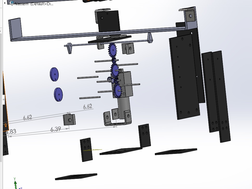
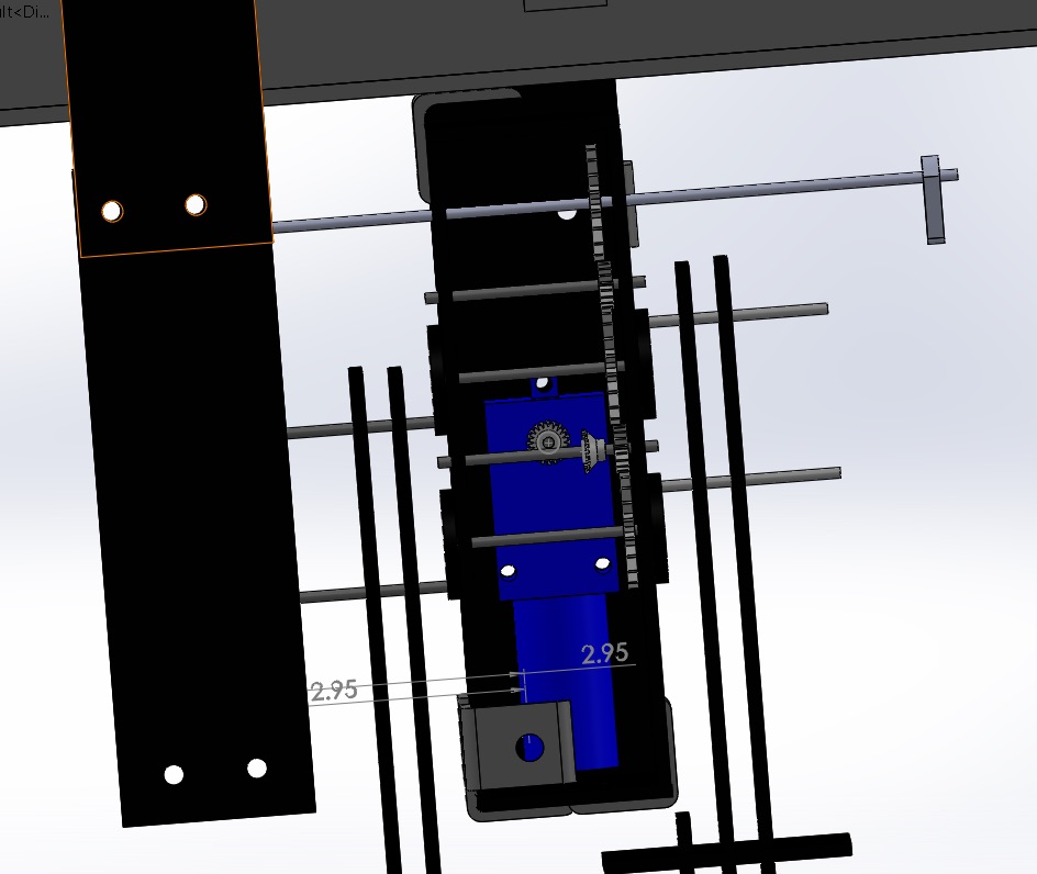
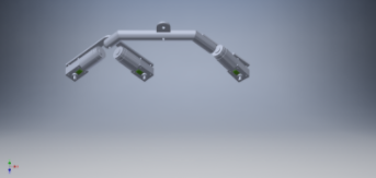
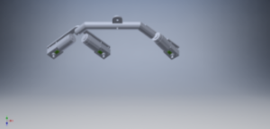
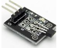
Magnetic Rotary Encoder
The rotary encoders are currently not placed on the rover. The encoders that may be used are the vetco hall effect sensor module. Below is a 3D model of where the encoders will be placed as well as the sensor
Modified Chassis Design Conclusion
The modified design was not tested. So to see if the modified design works, testing should be done before modifying or applying a new design. Assuming this modified design can work properly, there will still be an issue. This new issue which was discovered near the end of the mission was that the solar panel stepper motors will rest on the rod connectors that connect the legs to the bar. This may not cause any issues initially but it would be best that this issue be avoided. A fix for this would be using the previous design’s differential bar and extending the rovers legs out approximately an inch and half from its current position using longer socket shoulder screws http://(https://goo.gl/wawpGJ . This design may have issues with having more force being applied onto the longer screw. So some stress testing may be required. An alternative design would be to completely get rid of the differential bar mechanism and opt in for a differential gear box mechanism. The following mechanism would have to be placed in between the battery and electrical box. Which will be an issue due to the battery being in the way of the connection points where the differential gear mechanism will be placed. So the battery may be required to be moved further back to allow this modification.
References
- https://docs.google.com/document/d/1NPQc2yRRpnUTUtxoxJKHqFgdvQKcfK46eKzEHFoKYcc/edit
- https://docs.google.com/presentation/d/18KhcQu9Qbvz87q95ofyxz0uMTzXnwRA5Ok51WPXzeXQ/edit
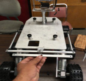
Electrical Box Setup
By Anthony Dunigan (Chassis – Design and Manufacturing Engineer)
The current cabling setup for the electrical box is shown below.

The box includes 3 VNH5019 motor shields that are stacked on top of each other. They are stacked to reduce the area that each individual driver would have taken in the box. An additional hole was drilled into the box to allow more wires to enter the box which will decrease the risk of the wires being frayed or pinched from entering only one access point.
Fuse Protection
An inline fuse was incorporated into the box to protect the circuitry and battery. The previous semester did not incorporate this mechanism. The fuse can go hold up to 20 Amps. But only a 5 to 6 amp fuse will be required for protection. A fuse over 6 amps is not advised due to the max output of the battery being approximately 7 amps and will increase the risk of damaging the battery and circuits. As well as protecting the battery from exploding! The fuse was placed before the switch to protect the switch as well.
Terminal Block/Power Distribution
An 8 block terminal was used to distribute power and ground. The terminal block requires a ring terminal connector. Each ring terminal is red due to the classification of the wires gauge size (16 gauge). The power wires are red while the ground wires are black. 3 of the power lines coming from the output of the terminal block are going to the 3 motor driver shields. 1 wire is connected to the step down voltage regulator. The voltage regulator steps down the 12 Volts from the battery to 5 Volts. The output of the regulator is connected to a breadboard that should supply the arduino leonardo, servo motor, and ultrasonic sensors. Be sure to double check the voltage and current ratings for all devices in the electrical box. The terminal block also has a custom polycarbonate glass protection on it. This should protect the terminal block from making contact with other electrical devices within the box.
Cabling Conclusion
The issue with current electrical box is that it is too small (7x5x3 cubic inches). A larger electrical box may be required to give sufficient room for all the required components that need to be placed. A larger electrical box will also allow you additional room just in case any additional components need to be placed inside such as the solar panel pcb and charge controller. The charge controller can have its own enclosure placed on the back side near the battery. But you must also consider the possible new mechanical design of the differential gearbox that may not allow the charge controller on the rear near the battery due to the new placement of the battery.
A smaller inline fuse may be used as well to increase the amount of room inside the electrical box. Additional fuses to be placed in line with the motor shields should be considered.
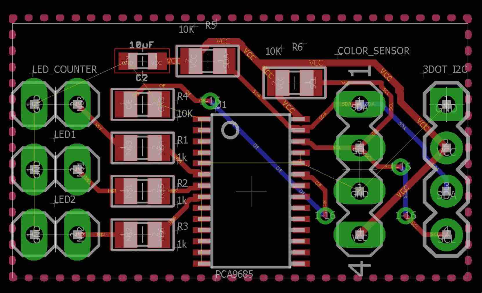
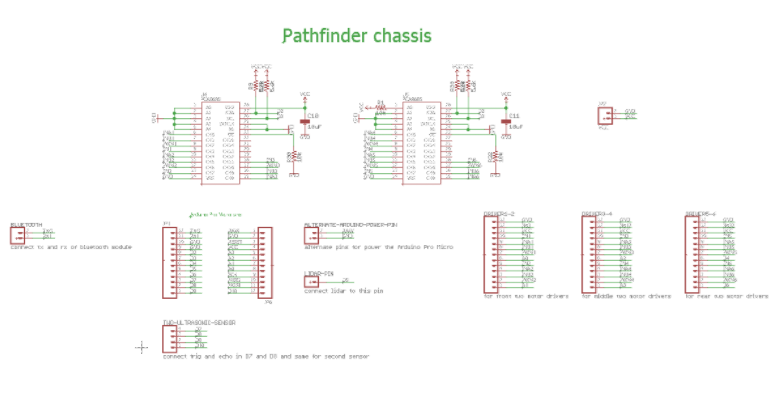
PCB
Schematic
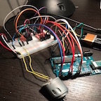
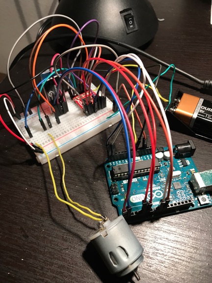
By Renpeng Zhang
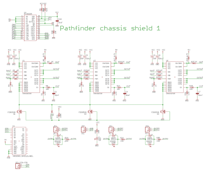
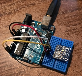
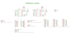
For the motor drivers and I2C expander, we decided to make it into a shield for Arduino. However, due to the size and number of the motor drivers; we weren’t able to put them into a single shield, so we decided to do two shields and stack them on top of the Arduino Leonardo. Due to the size of the heatsinks on the motor drivers, we have to design the shield in such a way where the top shield won’t cover up the motor drivers on the bottom shield. After careful considerations, we decided to put one PCA9685 I2C expander with three motor drivers on the first shield and the other PCA9685 I2C expander with the other three motor drivers on the second shield. The schematics for the two shield are identical except for the current sensing pins. The first shield utilizes the first 3 analog pins and the second shield utilizes the last 3 analog pins.
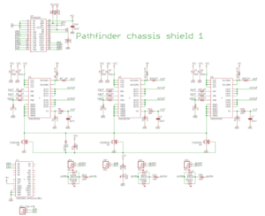
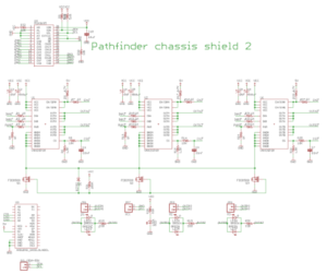
New design as a platform for Pololu VNH5019 dual motor drivers
Solar PCB
Previous Semester’s PCB was assembled. Still needs cleaning up.

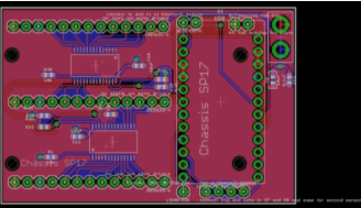
Chassis – PCB Layout
By Anthony Dunigan (Chassis – Design and Manufacturing Engineer)
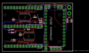
Without Polygon

With Polygon
This is the completed or the most recently updated version of the custom PCB. This current version of the PCB will consist of 2 PCA9686 IC’s (I2C), multiple resistors and capacitors. The layout consist of 3 VNH5019 motor shield connectors. There will also be arduino micro connectors, power pin connectors, lidars sensor connector, bluetooth connectors, and an alternate arduino pwr connector. This custom PCB will be using existing parts within the chassis. The existing parts are the motor shields and bluetooth. The additional parts needed will be the arduino micro. The PCB size is about 4 square inches. Includes holes for mounting the PCB.
Reference
- https://drive.google.com/open?id=0B9ZODu6tlNEcUnZkNWFUNWVKY3c
- From the Chassis_5_5 folder. File: Chassis_5_5D4.brd
Software
By Renpeng Zhang
General Software Flowchart

Rover control flowchart

Solar Panel State Flowchart

Verification Matrix
By Abdullah Albelbisi (Mission System and Test)
https://drive.google.com/open?id=0B3RM6QKrhjFIMzJsQkdUU0taOVE
https://drive.google.com/open?id=1xGVLvXXeleSxb98yUkLiqC7xg8m5uiotWOjMOk3OwaA
Project Documentation
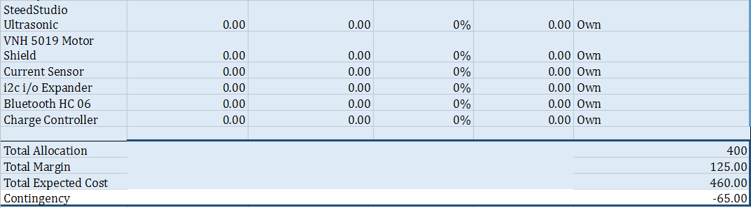
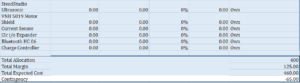
Resource Report
By Everyone

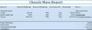
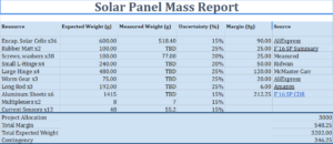
https://drive.google.com/open?id=1_Cagu3YueXAvwMQgK7jMg-9QrC4VUImQfjhPlNaiu9Y
Cost Report
By Everyone

https://drive.google.com/open?id=1_Cagu3YueXAvwMQgK7jMg-9QrC4VUImQfjhPlNaiu9Y
Schedule
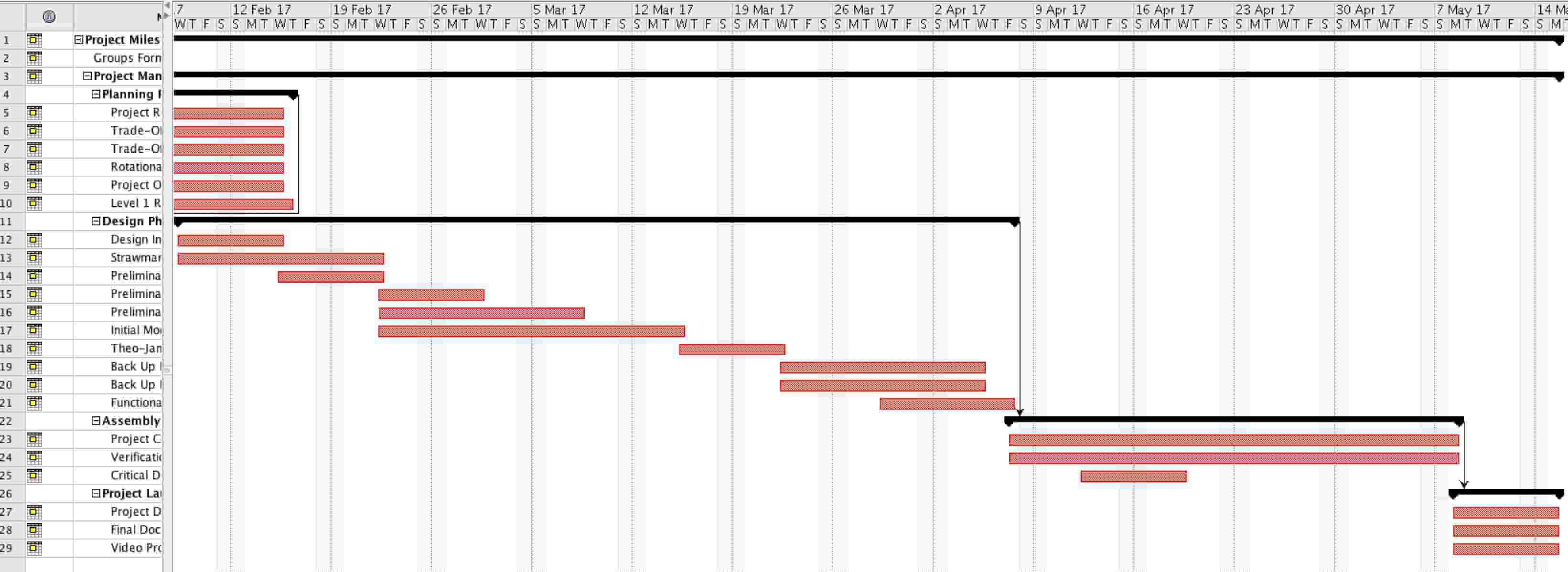
By Martin Diaz (Project Manager)
The schedule was created using project Libre. The task were separated by division and then scheduled with the critical tasks in mind.
https://drive.google.com/open?id=0Bz6ZQqAMFyLHSG5tTl9rQm15Yk0
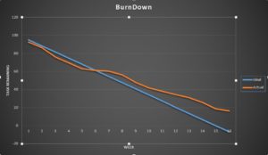
Burndown
By Martin Diaz (Project Manager)
The burndown was created by getting each task from the project Libre into excel and then assigning percent completion for each week.
https://drive.google.com/open?id=0Bz6ZQqAMFyLHUThNWkgzQy1YdE0
Creativity
https://drive.google.com/open?id=104MTPy6nEF7KAQX6WpWLSnreQI6UHw2A80UVELk3wzg
PDR
https://drive.google.com/open?id=1vk9dVFMz31RVrXSXGV3NOuN1yaQoOdQNtvI5ly98sz8
CDR
https://drive.google.com/open?id=1soV0-mG75nks4ojD8DVIlJpCzfBcPZe9JpZQoynt9Ls
What We Learned From This Semester
By Martin Diaz (Project Manager)
One of the things I learned late in the semester was to ask the division for help. Don’t assume they won’t want to help you. The division managers can step in and help your project a lot and even get their engineers from other projects to help support your project.
Asking Professor Hill is also a lot of help. Especially with circuit design, schematics, and PCB layout. We were having a lot of trouble trying to make our custom PCB on our own and then went to Prof. Hill for help. He said he enjoys circuit design and wished we had seen him sooner. If we had we would have completed our PCB in time.
One of the difficulties the group had was not be able do work on the project because one of the members had certain parts. I suggest getting similar parts from Prof. Hill so they can work on similar systems. For example you can 6 smaller motors and breadboard them to test your code instead of waiting for a chance to work on the actual motors you are going to use.
Project Video
https://drive.google.com/open?id=0B4jU8uMDmOoiYW52NWhSTVc1ZDg
Resources
EagleCAD Files – https://drive.google.com/open?id=0B_Kn5EG3fBjuejZyajBfYWVKWE0
Fritzing Files – https://drive.google.com/open?id=0B_Kn5EG3fBjuaURKRTBUR2M3QTA
Arduino Code – https://drive.google.com/open?id=0B_Kn5EG3fBjuMV9MZERvaENvUVE
Solar Design and Manufacturing Files – https://drive.google.com/open?id=0B4jU8uMDmOoiVVp5dkFRbC1jRTA
Chassis Design and Manufacturing Files – https://drive.google.com/drive/folders/0Bz6ZQqAMFyLHcXlsVm5lNUlIeXc?usp=sharing
Verification and Validation – https://drive.google.com/open?id=0B3RM6QKrhjFIR3JqcHZLRmVmUDA
Bill of Materials – https://docs.google.com/document/d/1fk77AdEc3pNCxLTQE3WCtPdG5hXLdYsb-yxXMa35l6k/edit?usp=sharing