Noise Requirement

written by: Fabian Suske

Approved and Edited by: Carolina Barrera

Table of Contents

Intro:

In order to fulfill the L2-13 subsystem requirement “Safety/Temperature sensor” a test has been carried out. This test followed the Verification and Validation Test Plan. The temperature sensor was implemented as a safety switch in the device. The feature is to prevent incidents when the components overheat, and the device could potentially become a hazard for the user’s safety.


Test Objective:

The test criteria that needs to be tested in this inspection is the following:


“Test Objective:  To successfully verify the L2-13 (Safety) requirement, the Prosthetic Arm shall implement a temperature sensor such that upon reaching unsafe operating temperature (above 55°C), the system will shut-off “[1]

Test Method

The test was set up in the following way:

  • Temperature sensor
  • Maker1000
  • C Algorithm to control the shutdown

Because of the incident while testing the kill switch, the Teensy MCU was not available for testing anymore. So, the temperature sensor was tested with the Arduino Maker1000 on a breadboard.

The breadboard was placed in a “temperature isolated” environment which was then heated up until the unsafe operating temperature of 55°C was reached. An indicator LED in the breadboard notified the system’s shutdown.


Test Conclusion:

Figure 1 shows that after the temperature reached the 55°C the Serial plotter stopped, and so we knew the shutdown had been initialized.

At the same time the LED indicating the shutdown went on in Figure 2.

The Serial Monitor also logged the temps and the shutdown. Figure 3 shows the analog serial values the temperature sensor was outputting.

[1] https://drive.google.com/drive/folders/0B3qlnfB-grPcVzJOTTZyemZ2R3c

Temperature Sensor / Safety

Written by: Fabian Suske

Approved and edited by: Carolina Barrera

Table of Contents

Intro:

In order to fulfill the L2-13 subsystem requirement “Safety/Temperature sensor” a test has been carried out. This test followed the Verification and Validation Test Plan. The temperature sensor was implemented as a safety switch in the device. The feature is to prevent incidents when the components overheat, and the device could potentially become a hazard for the user’s safety.


Test Objective:

The test criteria that needs to be tested in this inspection is the following:


“Test Objective:  To successfully verify the L2-13 (Safety) requirement, the Prosthetic Arm shall implement a temperature sensor such that upon reaching unsafe operating temperature (above 55°C), the system will shut-off “[1]

Test Method

The test was set up in the following way:

  • Temperature sensor
  • Maker1000
  • C Algorithm to control the shutdown

Because of the incident while testing the kill switch, the Teensy MCU was not available for testing anymore. So, the temperature sensor was tested with the Arduino Maker1000 on a breadboard.

The breadboard was placed in a “temperature isolated” environment which was then heated up until the unsafe operating temperature of 55°C was reached. An indicator LED in the breadboard notified the system’s shutdown.


Test Conclusion:

Figure 1 shows that after the temperature reached the 55°C the Serial plotter stopped, and so we knew the shutdown had been initialized.

At the same time the LED indicating the shutdown went on in Figure 2.

The Serial Monitor also logged the temps and the shutdown. Figure 3 shows the analog serial values the temperature sensor was outputting.

Resources

[1] https://drive.google.com/drive/folders/0B3qlnfB-grPcVzJOTTZyemZ2R3c

Kill Switch / Safety

Written by: Fabian Suske

Edited and Approved by: Carolina Barrera

Table of Contents

Intro:

In order to fulfill the L2-12 subsystem requirement “Safety/Kill switch” a test has been carried out. This test followed the Verification and Validation Test Plan.


Test Objective:

The test criteria that needs to be tested in this inspection is the following:


“Test Objective:  To successfully verify the L2-12 (Safety) requirement, the Prosthetic Arm shall implement an electronic kill switch allowing the user to shut-off the system in case of an emergency “[1]


Before the MCU is integrated, a basic functionality test has to be carried out.

Test Method

The test was set up in the following way:

  • Power supply
  • PCB
  • Teensy
  • C Algorithm to control the enable pin

The PCB was hooked up to the power supply. The Enable jumper was shorted, and the system powered up. When the jumper is removed, the power in the PCB should shutdown.

Afterwards the MCU should be able to control the Enable pin.

The Teensy MCU was connected to the PCB. Once connected, the PCB was powered up. The MCU sends a high signal to the Enable Pin of the 14-12V LDO. Upon the successful reading of the high signal, the Enable Jumper was removed. Setting the Enable pin to low the power should cause the LDO to turn OFF.


Test Conclusion:

The first test was performed successfully. When the Enable Pin was shorted, the LDO provided power to all subsystems and Power was available on the 12V and 5V outputs. Once the jumper was removed, the power in the outputs dropped, and the system works as designed. An oscilloscope was hooked up to the PCB to measure the performance of the power off.

The following time was measured:

  • Reaction time of the LDO
  • Shutdown time
  • Total time of shutdown

The time after the Enable signal drops (the reaction time- blue/Ch3) until the Voltage drops(green/CH2) obtained in the measurements was 4ms roughly.

The shutdown time -the time it takes the system to drop from 12 to 0V, was measured, and 5ms were obtained.

The total time of shutdown was calculated as the sum of the two previous times. Hence, it can be concluded that the system shuts down completely 9ms after the Enable was set to low.


After this, a second test was performed. In order to control the Enable pin through software, the MCU was connected to the PCB, but in this part of the testing we had the PCB behaving unusual.

When the MCU was connected to the board, and the Enable jumper was removed from the board, the system stayed ON. Another option to shut the system down was to force the output in the Enable pin to low, but that didn’t work either. After a couple of tries, the MCU was not programmable anymore. It’s unclear up to this point what could have occasioned the malfunction. Probably the Pin design to pull the Enable pin down was shorted to 12V by accident. As a result, the MCU fried, and was left inoperable.

In conclusion, the Hardware implementation of this power off works. When the MCU was introduced to control, the action of powering off the system didn’t do what it was supposed to, and a short might have left the MCU broken presumably. Therefore, the test failed but it was still completed around 50%.

Resources

[1] https://drive.google.com/drive/folders/0B3qlnfB-grPcVzJOTTZyemZ2R3c

Portability (L2-8)

written by: Fabian Suske

Approved and edited by: Carolina Barrera

Table of Contents

Intro:

In order to fulfill the L2-8 subsystem requirement “Portability” an inspection has been carried out. This test followed the Verification and Validation Test Plan. This requirement is basically to ensure the arm can be operation for 20 minutes – as agreed, and justified in previous stated requirements.


Test Objective:

The test criteria that needs to be tested in this inspection is the following:


“Test Objective:  To successfully verify the L2-8 (Portability) requirement, the Prosthetic Arm battery system shall allow the user mobility, as to permit a 20 minute operation without constraining the user to a wired connection to the mains grid, or generation source.“[1]


This requirement goes along with duration, and both entail the success in the battery selection. If the team chose the right battery, then the arm will be able to operate for 20 minutes continuously, and ideally, it would not need to be recharged until the meal is finished. Therefore, the battery has been hooked up to the PCB and the both critical Voltages read.


Test Method

The test was set up in the following way:

  • Battery
  • PCB
  • DMM

After the battery was hooked up, the DMM was used to measure the Voltage for 12V and 5V at the respective points. These readings are the power to the MCU and the motor. From the arm MCU there are wires that power the Hand’s MCU, and the motors in the wrist and fingers. This is the reason for having these two requirements for battery selection.

Figure 1 shows the mount of the battery inside the bicep, and Figure 2 and Figure 3 show the reading of the output voltages from the PCB.

Test Conclusion:

The first positive indication was that all status/power LED’s light up. This means the battery is able to provide at least 6 V to the Buck Converter. The following measurement ensured that the Voltage levels outputting the right values.

[1] https://drive.google.com/drive/folders/0B3qlnfB-grPcVzJOTTZyemZ2R3c

Waypoint Navigation

Waypoint Navigation for the Pathfinder

By Jose Alcantar, Electronics and Controls Engineer

Introduction:

This blog post covers the proposed waypoint navigation algorithm along with some issues regarding how the GPS data was transmitted and decoded by the Arduino. Sample code and navigational calculations are included.

Navigation Algorithm:

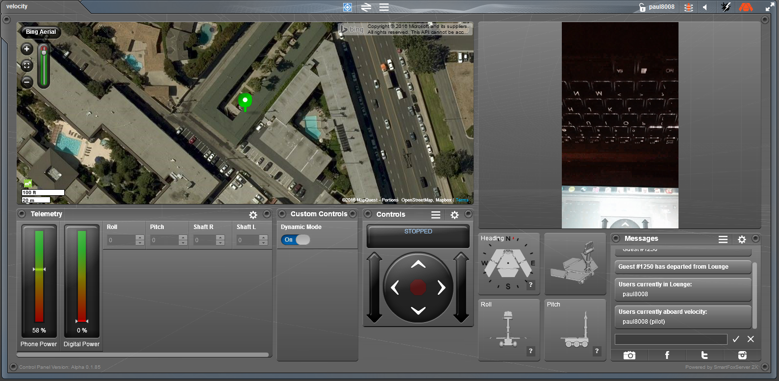
When the pathfinder travel mode is to Autopilot, the Arxterra App begins transmitting heading information, current coordinate information of the smartphone and waypoint coordinates, if any. The basic control logic is as follows:

  1. If Autopilot mode is engaged, begin Waypoint Navigation
  2. Process any new GPS information and update the course and distance to the target waypoint.
  3. Read heading information to get current bearing and decide the desired direction to turn the pathfinder.
  4. Begin moving the pathfinder and check for any obstacles to avoid.
  5. If waypoint is reached, switch to manual control.

The code to handle each of these was written in separate functions.

Autopilot Mode:

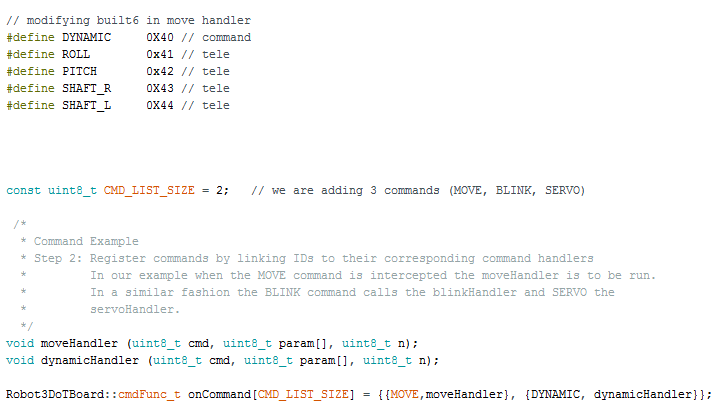
When the autopilot mode is engaged the WAYPOINT_ON command is called, which begins the Navigation algorithm. The first function called retrieves the heading information from the smartphone which is sent as a data packet containing the command id and the heading information in hex values. For more detail regarding formatting the data see link below,

http://arxterra.com/heading-and-gps-coordinates-formatting/

After the heading is retrieved, a function is called to calculate the difference between the current heading and the heading to the desired waypoint.

The following code demonstrates how to calculate the turn:


// returns distance in meters between two positions, both specified

// as signed decimal-degrees latitude and longitude. Uses great-circle

// distance computation for hypothetical sphere of radius 6372795 meters.

// Because Earth is no exact sphere, rounding errors may be up to 0.5


void calcDesiredTurn(void)

{

//calculate where we need to turn to head to destination

headingError = targetHeading – currentHeading;


//adjust for compass wrap

if (headingError < -180)

headingError += 360;

if (headingError > 180)

headingError -= 360;

// calculate which way to turn to intercept the targetHeading

if (abs(headingError) <= HEADING_TOLERANCE) // if within tolerance dont turn

turnDirection = straight; // GO FORWARD

else if (headingError < 0)

turnDirection = left;     // TURN LEFT

else if (headingError > 0)

turnDirection = right;    // TURN RIGHT

else

turnDirection = straight; // GO FORWARD

} // calcDesiredTurn()


After the target heading is calculated, the distance to the target waypoint is calculated using the following code:

int distanceToWaypoint()

{


float delta = radians(currentLon – waypointLon);

float sdlong = sin(delta);

float cdlong = cos(delta);

float lat1 = radians(currentLat);

float lat2 = radians(waypointLat);

float slat1 = sin(lat1);

float clat1 = cos(lat1);

float slat2 = sin(lat2);

float clat2 = cos(lat2);

delta = (clat1 * slat2) – (slat1 * clat2 * cdlong);

delta = sq(delta);

delta += sq(clat2 * sdlong);

delta = sqrt(delta);

float denom = (slat1 * slat2) + (clat1 * clat2 * cdlong);

delta = atan2(delta, denom);

distanceToTarget =  delta * 6372795;

//————-Edit to turn off navigation———-//

// check to see if we have reached the current waypoint

if (distanceToTarget <= WAYPOINT_DIST_TOLERANCE)

waypoint_on = 0;

//—————————————————//

return distanceToTarget;

}  // distanceToWaypoint()


The previous functions return the new heading in degrees and the distance in meters

the next function, checkSonar() is called to read the ultrasonic sensor distance values.


void checkSonar(void)

{

distR = 0; distL = 0;

digitalWrite(11,LOW);

delayMicroseconds(2);

digitalWrite(11,HIGH);

delayMicroseconds(10);

digitalWrite(11, LOW);


pulse_width = pulseIn(8, HIGH);


distR = (pulse_width/2)/29.1;

delay(60);


digitalWrite(10,LOW);

delayMicroseconds(2);

digitalWrite(10,HIGH);

delayMicroseconds(10);

digitalWrite(10, LOW);


pulse_width = pulseIn(4, HIGH);

distL = (pulse_width/2)/29.1;


delay(60);


if( distR > MAX_DISTANCE_IN && distL > MAX_DISTANCE_IN)

{

distR = MAX_DISTANCE_IN;

distL = MAX_DISTANCE_IN;

}


}  //checkSonar()

After calculating the distance, target heading and reading the sensor values the moveAndAvoid() function is called to move the pathfinder to its destination while avoiding obstacles.

void moveAndAvoid(void)

{

if(distL >= SAFE_DISTANCE && distR >= SAFE_DISTANCE)    //no close objects in front

{

if(turnDirection == straight)

{

speedLeft = FAST_SPEED;         //PWM SIGNAL FOR BOTH MOTORS

speedRight = FAST_SPEED;

left_forward();

right_forward();

}

else if(turnDirection == left)

{

speedLeft = TURN_SPEED * .85;         //PWM RATIO FOR BOTH MOTORS

speedRight = TURN_SPEED;

left_forward();

right_forward();

}

else if(turnDirection == right)

{

speedLeft = TURN_SPEED;

speedRight = TURN_SPEED * .85;

left_forward();

right_forward();

//driveMotor->setSpeed(speed);

//driveMotor->run(FORWARD);    // turn direction

//turnMotor->run(turnDirection);

//else(turnDirection == right)

//speed = TURN_SPEED;

}

return;

}

if ((distL > TURN_DISTANCE || distR > TURN_DISTANCE)  && (distL < SAFE_DISTANCE || distR < SAFE_DISTANCE)) //not yet time to turn, but slow down

{

if(turnDirection == straight)

{

speedLeft = NORMAL_SPEED;   // PWM FOR MOTORS

speedRight = NORMAL_SPEED;

left_forward();

right_forward();

}

else if(turnDirection == left)

{

speedLeft = TURN_SPEED * .85;     //SPEED RATIO FOR MOTORS

speedRight = TURN_SPEED;

left_forward();

right_forward();

// already turning to navigate —-> Direction to turn

}

else if(turnDirection == right)

{

speedLeft = TURN_SPEED;

speedRight = TURN_SPEED * .85;

left_forward();

right_forward();

}

return;

}

if ((distL < TURN_DISTANCE || distR < TURN_DISTANCE) && (distL > STOP_DISTANCE || distR > STOP_DISTANCE)) // getting close, time to turn to avoid object

{

speedLeft = SLOW_SPEED;     //PWM FOR MOTORS

speedRight = SLOW_SPEED;

left_forward();

right_forward();

switch(turnDirection) // decides whether to turn left or right

{

case straight:        // going straight

{

if (headingError <= 0)

turnDirection = left;

else

turnDirection = right;

speedLeft = SLOW_SPEED;

speedRight = SLOW_SPEED * .85;

left_forward();

right_forward();

//turnMotor->run(turnDirection);  // turn in the new direction

break;

}

case left:                        // if already turning left, try right

{

speedLeft = SLOW_SPEED;

speedRight = SLOW_SPEED * .85;

left_forward();

right_forward();

//turnMotor ->run(TURN_RIGHT);

break;

}

case right:

{

speedLeft = SLOW_SPEED * .85;

speedRight = SLOW_SPEED;

left_forward();

right_forward();

//turnMotor ->run(TURN_LEFT);

break;

}

} //end SWITCH


return;

}


if (distL <  STOP_DISTANCE || distR < STOP_DISTANCE)          // too close, stop and back up

{

left_release();

right_release();

//driveMotor->run(RELEASE);            // stop

//turnMotor->run(RELEASE);             // straighten up


turnDirection = straight;

speedLeft = NORMAL_SPEED;

speedRight = NORMAL_SPEED;

left_reverse();

right_reverse();

//driveMotor->setSpeed(NORMAL_SPEED);  // go back at higher speet

//driveMotor->run(BACKWARD);

while (distL < TURN_DISTANCE || distR < TURN_DISTANCE)       // backup until we get safe clearance

{

currentHeading = readCompass();    // get our current heading

calcDesiredTurn();                // calculate how we would optimatally turn, without regard to obstacles

checkSonar();

delay(100);

} // while (sonarDistance < TURN_DISTANCE)

left_release();

right_release();

//driveMotor->run(RELEASE);        // stop backing up

return;

} // end of IF TOO CLOSE


} //moveAndAvoid


NOTES: One of the main issues with the waypoint navigation is that the heading data received does not give the full 0 – 360 degree range. When formatting the data, the heading is given from 0 to 180 degrees (North = 0 and South = 180) going counter clockwise, but any heading past 180 degrees does not transmit correctly. When formatting, the values given from the data packet, the degree range from (180 to 360) loops back, (going counter clockwise) the degree range is North = 180 and South = 360 degrees this causes an issue with calculating the correct heading values. It is recommended that Jeff is contacted to resolve this issue.


Conclusion:

With the following algorithm the pathfinder should be able to reach its destination with no issues.

Stress Test

Stress Test

By: Nick Lukin (Design and Manufacturing Engineer) 

Introduction

In order to ensure that the Pathfinder chassis could support the weight of the solar panels in order to properly interface it was necessary to perform a stress/displacement test in Solidworks. The solar panels overall weight was a maximum of 50lbs. The chassis was designed so the panels could sit on top of aluminum standoffs welded to the top plate of the chassis. The force in Newtons was calculated and applied to the standoffs.


one

Figure 1: Stress Test Results

two

Figure 2: Stress Test Results Continued


Analysis

In order to figure out the appropriate force to apply to the model it was necessary to convert the maximum weight of the solar panels into Newtons (1 Newton = 0.2248 lbs). Therefore 50 lbs converts into about 222 Newtons. This number was used for the simulation in order to see how much the maximum weight of the solar panels would affect the chassis. Figures 1 and 2 show the results of the stress test performed in Solidworks. The test results show an exaggerated view of exactly how and where the chassis would begin to deform. It is noticed that the chassis max deformation is about 8.017e+004 von Mises which is very little. The overall characteristics and shape of the deformation is as expected.

three

Figure 3: Displacement Results

four

Figure 4: Displacement Results


Figures 3 and 4 show the displacement of the chassis and further show how the chassis will be affected by the maximum weight of the solar panels. The displacement results give a millimeter value of exactly how much the metal will move. It is noticed that the top plate bends a maximum of 1.226e-003 mm which is very small (less than a millimeter). This number is acceptable and confirms that the design of the chassis can withstand the maximum weight of the solar panels.

Conclusion

After running the appropriate stress tests in Solidworks it was determined that the design shown in the figures above was strong enough to support the weight of the solar panels. Being that the chassis is the base of the entire pathfinder it must support the weight of everything that is attached to it. The stress tests performed show the strength of the chassis and confirm that the requirement of properly interfacing between the chassis and solar panels is achieved.

Form Factor

From Factor

By: Nick Lukin (Design and Manufacturing Engineer)

picture1n


Introduction

In order to meet the requirement of the Pathfinder being dimensionally proportional to the actual Spirit and Opportunity rovers it was necessary to develop a measurement method in order to properly scale the overall design.

picture2n

Figure 1: Small Scale Model

Analysis

A small scale model of the actual spirit/opportunity rover was used in order to get base dimensions to work with and to develop an appropriate scale factor. Figure 1 shows the small model that was used to take measurements from. 10 different measurements were taken from the small model. The measurements are summarized in Figure 2.

picture3n

Figure 2: Summary of Measurements/Dimensions

The solar panels group was limited to how wide they could make their overall panels because they needed to be able to fit inside the cabinet in ECS 316. The cabinet is 19 inches wide which meant the max width of the center solar panel was to be 19 inches. Therefore the scale factor of the overall design relied on how wide the solar group decided to make their panels. The final overall width and length of the solar panels was 25.39” and 36.26” respectively. The center panel width was 18.45” which was within the cabinet measurement of 19”. Once the solar panel group finalized their measurements the proper scale factor could be calculated. Dividing the overall solar panel width and length by the small model width and length gave a scale factor of 10.097.

npicture5

Figure 3: Overall Height

In order to find the overall height of the solidworks model the overall height of the small model (29.6mm) needed to be multiplied by 10.097. The result is about 298.88mm or 11.77 inches as shown in figure 3.

npicture1

Figure 4: Overall Width (wheel to wheel)

The overall width wheel to wheel on the small model was 44mm. Multiplying this number by the scale factor yielded a measurement of about 444.29mm or 17.49 inches as shown in figure 4.

npicture2

Figure 5: Length (wheel middle to front)

The length between the center of the front wheel and the middle wheel on the small model was 30.2mm. Multiplying this number by the scale factor yielded a measurement of about 304.9mm or 12.01 inches as shown in figure 5.

npicture3

Figure 6: Length (wheel middle to back)

The length between the center of the middle wheel to the center of the rear wheel on the small model was 20.4mm. Multiplying this number by the scale factor yielded a value of 205.99mm or 8.11 inches as shown in figure 6.

picture1n

Figure 7: Side Solar

The measurement between the end of the side solar panel and the edge of the wheel on the small model was 22.8mm. This number was multiplied by the scale factor to get a number of about 230.22mm or 9.05 inches as shown in figure 7.

npicture11

Figure 8: Front Solar Measurement

The measurement between the front of the solar panel edge and the front edge of the wheel was 4.4mm on the small model. After multiplying by the scale factor the measurement came out to 44.43mm or 1.75 inches as shown in figure 8.

npicture

Figure 9: Back Solar Measurement

The measurement between the back solar panel edge and the edge of the back wheel on the small model was 3.5mm. Mulitplying by the scale factor yielded a measurement of 35.34mm or 1.39 inches as shown in figure 9.


npicture9 npicture10

Figure 10: Length/Width Solar Panels

The overall length and width of the small model solar panels was 92.5 and 63 mm respectively. Multiplying by the scale factor yielded measurements of 36.26 and 25.39 inches respectively as shown in figure 10.


npicture11

Figure 11: Phone Holder Height

The measurement of the phone holder from the top plate of the chassis to the very top of the phone on the small scale model was 34.4mm. Multiplying by the scale factor yielded a value of 347.35mm or 13.68 inches as shown in figure 11.

Conclusion

Overall we were successful in creating a model in solidworks that matched the proper form factor of the spirit/opportunity rovers. In order to properly achieve the correct proportions it was necessary to assume that the small scale model that was used was accurately proportional to the actual spirit/opportunity rovers. If this is the case our model meets the requirement of achieving the proper form factor. A plus or minus 0.25 tolerance was put on the actual building of the model to account for any errors during the fabrication process.

Fall 2016 Velociraptor (W): Requirements

By: Gifty Sackey (Mission, System and Test Engineer)

Approved by:

– Lam Nguyen (Project Manager)

– James Lee (Division Manager for Mission, System and Test)


Level 1 Requirements


  1. The 3rd generation Velociraptor (W) budget shall not cost more than $102. This estimate is based upon the customer and project team agreement on October 7th, 2016
  1. The 3rd generation Velociraptor (W) biped robot shall demonstrate its capabilities during EE 400D Final for Wednesday on December 14, 2016 according to the CSULB Calendar 2016-2017 Final at 9:00 am.
  1. The 3rd Generation Velociraptor (W) should resemble a Velociraptor of the Theropodous Dinosaur Suborder. [1]
  1. The 3rd Generation Velociraptor (W) will use a 3DoT board embedded system.
  1. The DC motor can support the mass of the robot with a 50% margin
  2. The 3rd generation Velociraptor shall operate for a minimum of one hour with an external power resource minimum of 1560 mA-Hours.
  1. The 3rd Generation Velociraptor (W) shall use an external PCB with an I2C interface as the 3DoT board.
  1. The velociraptor shall use a 3DoT board library and utilize I2C to communicate with sensors, A/D converter, and GPIO. [4]

Level 2


  1. The 3rd generation Velociraptor shall weight no more than 350 grams
  2. The 3rd Generation Velociraptor (W) shall turn 0-360 degrees on one leg under one minute
  3. The 3rd generation Velociraptor (W) shall create custom commands to be used with the Arxterra Control Panel
  4. The velociraptor shall use the IMU MPU6050 that tracks acceleration and gyration that can provide X and Y angles to +/- 6.5 degree precision
  5. The velociraptor shall use a rotary sensor that tracks at 90 degrees’ precision to determine the position of leg. The leg position controls the head and tail location
  6. The velociraptor shall support the mass of the robot with a 50% margin, 522g in a 0 degree position (Footstep is down on the ground)
  7. The velociraptor shall support the mass of the robot with a 50% margin, 522g in a 90 degree position (Center of foot path on ground)
  8. The velociraptor shall support the mass of the robot with a 50% margin, 522g in a 180 degree position (Time before foot goes to ground)
  9. The velociraptor shall control the head and tail movement with a single servo using gear trains
  10. The head and tail shall use one servo that operates at an optimal torque of 18-45mN-m to maintain center of gravity
  11. The CoG on the axis of the H/T shall be controlled by one servo while being placed over the foot
  12. The velociraptor will not exceed a rating of 1A with the use of the LDO with the external PCB
  13. The velociraptor shall utilize custom telemetry commands that will be displayed on the Arxterra Control Panel
  14. The 3rd generation velociraptor shall walk on a flat surface
  15. The 3rd generation velociraptor shall walk on a surface texture
  16. The 3rd generation velociraptor shall walk on an incline and decline surface
  17. The 3rd generation velociraptor should perform dynamic walking while on a flat surface
  18. The 3rd generation velociraptor should perform dynamic walking while on a surface texture
  19. The 3rd generation velociraptor should perform dynamic walking while on an incline and decline.
  20. The 3rd generation velociraptor should perform dynamic walking while on a step

Resources


[1]  http://www.mokonut.com/app/com.bkminegames.b005/dinosaur-mods-for-minecraft/

Fall 2016 Velociraptor (W): Bluetooth Commands

By: Gifty Sackey (Mission, System and Test)

Approved by:

– Lam Nguyen (Project Manager)

– James Lee (Division Manager for Mission, System and Test)

Introduction

This blog post will be discussing velociraptor’s communication system; the ArxRobot app and the Arxterra Control Panel that is used to control the robot. At this point in time, the velociraptor group has been able to settle on a design for the velociraptor robot and is currently working on the systems and electronic controls for the robot.

Commands

The velociraptor robot will be able to receive commands through two main modes. It will be either through the community mode or remote control mode. In the event that the velociraptor will be receiving commands from the android phone, the Arxterra app would need to be configured into a remote control mode to make it possible. On the task bar located on the first line of your app, select the button that resembles the app logo merged with the phone. Once the user selects this, they can then select remote control mode.  If the user would like to change the control settings back to the control panel, follow the steps above regarding which tab button to select but instead choose the community mode to activate the control panel. When the control commands are sent from an android phone to the velociraptor robot, this communication is made possible with the help of the HM-10 Bluetooth module embedded in the 3DoT board with the help of WIFI or data services from the phone company.

a

Diagram 1: This shows when the robot has been located before boarding.

b

c

Students are allowed to have custom commands on the app and have the commands be unique to their robot. Command types must have their own unique identifier called a Command ID. These ID’s can be chosen from a range of 0x40 (64) to 0x5F (95). For our velociraptor group, we will have a custom command for static walking. The custom command for walking is being defined with the hexadecimal number 0x42. The static walking custom command has been created as a Boolean type whereby the user is allowed to either select an on or off. By default, the static walking custom command is created to be in the off mode.

d

The following image provided below displays the control panel after the Velociraptor robot has been boarded from the control panel. On the control panel, towards the right side of the screen the app connects to the phone’s camera. Aside from the custom commands that can be designed by students, there are some examples of telemetry commands that are embedded in the application.  Amongst these are options for the user to be able to display the phone’s battery, roll and pitch. Students are able to access these modes through the robot capabilities configuration.

Conclusion

In order to have the custom commands displayed on the control panel, the user has to select the community mode. On the other hand, to be more secure with the robot and its commands, users are also allowed to control the robot using the remote control mode option instead. When user’s control the robot from the remote control (phone), they are limited with the options and commands they see on the screen.

e

Diagram 1: This shows when the robot has been located before boarding.

f

Diagram 2: Clicking on the green robot allows students to board the robot

g

Diagram 3: Shows the communication to the phone’s camera

Velociraptor (Th) Final Documentation

By: Paul Ahumada, Project Manager

Members:

Kevin Armentrout, Electronics and Control Engineer

Victoria Osaji, Manufacturing and Development Engineer

Table of Contents

Project Overview

Mission Profile

3rd Generation Velociraptor is a robot developed by the CSULB 2016 Fall Semester class that will compete in a Jurassic/Modern Game: Save The Human with other toys on the last day of class, December 15, 2016. The game will involve Velociraptor chasing another robot through various terrain by tele-robotic communication on the Arxterra Control Panel. The arena and terrain the Velociraptor must traverse is developed by the Game Committee. The mission will display the robotic applications of the 3DoT Board developed by Arxterra and Velociraptor’s movement capabilities. – PM Paul Ahumada

Project Objectives

  • The Velociraptor is a dinosaur toy
  • The Velociraptor is on a deadline
  • The Velociraptor will use a 3DoT board
  • The Velociraptor will be controlled by an Arxterra Control Panel
  • The Velociraptor will play in a game

The premise of the Project Objectives is that they are derived from the Mission Profile. These objectives that have been simplified will establish every requirement that will be used to build the Velociraptor (Th) robot.

System Design

System Block Diagram

r2_system-block-diagram

The system block diagram is an overview of what is needed int he project. Different systems can be viewed from this picture. The blue colors are for the linear actuators and sensors not located on the external PCB or 3DoT Board. Purple is for the mechanical characteristics of the robot. Red is for external power that is not on the external PCB or 3DoT Board.

One unique modification to the 3DoT board is bypassing the boost converter which can be seen in the System Block Diagram image. There was a current limit to the boost converter the Velociraptor team wanted to avoid because the maximum currents for the DC motors was above the current limit for the boost converter and polyfuse and be detrimental to a demonstration if an issue occurred.

Subsystem Design

Interface Definitions

Interface Matrix

3DoT Board Available Pins

interace-matrix

The interface matrix for available pins lets the Velociraptor Team know what is readily accessible to use and which connector it will be located at. It is as if one looks at the 3DoT board as a black box with several inputs and outputs. The Available pins has every input and output located on the 3DoT Board and what it will be connected to in the project. The rows are what the 3DoT Board has and the columns are what the team intends to connect to the 3DoT board.

MCU Pins

interface-pins

The MCU Pin connections image purpose is for coding. Every pin from the MCU is accounted for and the programmer can determine what they intend each pin’s function. There are pins on the MCU that cannot be accessed and have end traces and are left as ‘end trace.’

Wiring Diagram

wiring-diagram

The wiring diagram is generated from feedback of the electronics and control engineer and is utilized as a reminder for what connections to purchase and what space must be allowed when sizing the mechanical model. The connectors for each actuator, external PCB, or sensor are labeled so no confusion occurs when assembling the PCB board.

Mission Command and Control

Software Block Diagram

r5_software-block-diagram

The Software Block Diagram began the process of writing the firmware and finding the needs for inputs from Arxterra. The software block diagram has a light blue color where firmware will take over coding. For static and dynamic walking, the robot needs to differentiate between the walking style and the easiest method to implement that was to have a dynamic push button.

An addition to the diagram would be that was originally not required of the project. As a goal, the team made it a challenge to send telemetry back to Arxterra.

Arxterra App and Arxterra Control Panel

Arxterra Phone App

phoneapp

When customizing the needs for Velociraptor’s custom Telemetry and Commands, the MST needed to start with the phone app. The phone app has custom command and telemetry Custom Entity Definitions that can be created and modified.

For telemetry, the team was interested in reading numerical values of roll, pitch, shaft right of the leg, and shaft left of the leg. Pitch and Roll are rotation angles from 180 to -180 degrees. The shaft positions are 0 to 360 degrees for the legs. The four variables are all singles (4 bytes) being sent to Arxterra Control Panel.

For commands, a dynamic mode button (boolean) would allow users to change between static and dynamic mode. By pressing the button, the servo used to control the body would be turned on/off.

Arxterra Control Panel

arxterraapp

The layout of the Arxterra Control Panel is generated after choosing the entities from the Arxterra App on the phone. The custom command and telemetry is displayed along with GPS and a live stream feed of video from the user’s phone.

Custom Commands and Custom Telemetry

Defining Custom Commands and Custom Telemetry and Declaration of Custom Command Functions

beginningThe custom commands and telemetry are defined at the beginning of the program to reserve their address space. Numbers below 0x40 are already defined elsewhere for built in commands and telemetry.

With newer versions of Arduino, functions that will be used for the custom commands are created before setup where the variable declaration is, similar to C++. The custom command for the dynamic button and move handler are used for Velociraptor. The reason a custom move handler is used is because there needed to be modifications for the motor control of the robot. The 3DoT board was designed for use with wheeled robotics and the Velociraptor is a biped. The DC motors need to be controlled with precision, which will be defined in firmware.

Telemetry Classes

packetsThe defined variables for telemetry are implemented into this section with the Packet Class. The constructor reads the unique variables so telemetry can be sent as different objects all part of the Packet Class.

  Sending Telemetrydata-sent

For telemetry being sent to Arxterra, a local variable is created that is cast into unsigned bytes. The local variable will be initialized as a casted variable setup elsewhere in the firmware. For example, the image above has a temp variable  casted as an unsign_16 and the right shaft reads that value to be sent out with the class function ‘sendSensor(…)’.

Electronics Design

Servo Design

Motor Design

IMU Design

IMU Implementation

Schematics

Firmware: E&C

Debugging Wire Library

3DoT and IMU

PCB Schematic E&C

Schematic

schematic

The schematic contains the SMD’s used for the external PCB required for Fall 2016. There is an I2C interface that has 4 wires coming from the 3DoT Board to the External PCB using Vcc, SDA, SCL, and Gnd.

Breadboard and Fritzing

bb

The schematic was placed onto a breadboard to see if the circuit behaved as the team wanted. The electronics and control engineer received outputs for the rotary sensors and the IMU sensor. These two sensors are what made our PCB external.

PCB Layout: MFG

PCB

Hardware Design: MFG

Mech-design

Verification & Validation Test Plans

validation_verification_testplans_r1

The Verification and Validation Test Plans is what our team had to complete for this semester. These items were determined by the customer in the Verification/Validation Matrices.

vv_velociraptor_thursday-1

The test plans have pass/fail tests for each requirement. For our Project, we failed all dynamic tests because of the lack of time and capability to implement a dynamic control mechanical model. The team was also not able to create a dinosaur image that the customer wanted and failed validations.

Project Status

Power Allocation

power-report

The Power Report shows that the Velociraptor team is at ~380mA and the Project Allocation is at 650mA. The robot at a 50% margin is 570mA and is thus at a safe operating range and has enough power being received to operate for over an hour based upon the CR123A being used.

Mass Allocation

mass-report

The Mass Report is based upon the torque needed to drive the robot, which is 657g at a 50% margin. The robot weighed 315g and that is below our 50% margin. The robot motors are capable of moving the mass.

Cost Report

costreport

The budgets were determined by the customer in October and this was based upon the cost allocations for each resource. The customer determined what could be provided and what could not be. In this report, their are items with $0.00 and they were provided by the customer. Items covered by the customer helped the team lower the budget to $95.71 and be below the Project Allocation set aside by the customer of $150.00.

Product Break Down Structure

pbs

The PBS looked at different categories that would create this project. The image lets the team know all the items that need to be completed for the project in different categories.

Movement Systems encompass actuators and mechanical modeling. Control has the sensors. Software Control has communication and programming applications. Power has all components that use power or deliver. 3DoT/PCB has SMD’s and connections the team must be aware of during project building.

Work Break Down Structure

wbs

From the PBS, tasks are divided among the engineers through the WBS. This semester was unique because we lost our Systems Engineer and the Project Manager had to take over that position. Roles of the System Engineer were covered by both PM’s of each Velociraptor.

Schedule

burndown

The Burn down Schedule has 3 graphs: expected project completion timeline (blue), actual project completion timeline (orange), percent completion (gray). As can be seen, the project lagged behind the expected project completion timeline and the team was forced to put in more time at the end of the semester. The complexity of the mechanical modeling, such as the legs, pushed back schedule and E&C’s capability to test the robot.

The project is 91% complete and misses implementation of rotary sensors with IMU, UCI linkage leg design, foot design, and firmware control algorithm.

Schedule-documents

Conclusion

The Velociraptor Project had challenges that proved difficult to get around. The UCI or Theo Jansen Linkages could not be implemented because the Simulation verse Real-world creation of the linkages was different. The delays caused by the leg sets pushed back the control algorithms used to move the robot and a simplistic version had to be created for final project demonstration. Also, the foot design for any biped is something that needs to be handled in the beginning and likely require an actuator to maintain the robot’s stability.

For future projects, the mechanical modeling is crucial to focus on because it will cause the project to fail. Lessons to take from this semester are:

  • Focus on leg linkage design early. How the linkages move when connected with screws is different than how they move in Solidworks
  • Do not ignore the foot design. The foot must be parallel with the body and the ground to increase stability. If not, the CoG will change as the pitch angle changes
  • Have Electronics and Control Engineer be familiar with I2C communication. The team was lucky to have an engineer more than capable of finding solutions to problems with I2C addressing locations for the sensors

CDR Document

PDR Document

BOM

Video