Fall 2016 BiPed : The Preliminary Design Documentation
By: Gifty Sackey (Project Manager)
Brandon Perez(Mission, Systems and Test)
Ryan Daly(Electronics and Control)
Ijya Karki(Manufacturing)
Mission Objective and Mission Profile
– Gifty Sackey (Project Manager)
The Robot Company has assigned our engineering team to design the 6th generation of the Biped robot, however, this model will utilize a non-servo based walking motion. The Biped should be able to statically walk with a final goal of being able to demonstrate dynamic walking. The Biped should be able to walk on various surfaces and walk on terrains that have an inclination of a maximum 6.5 degrees. In addition to that, the Biped need to walk around while avoiding obstacles with the help of ultrasonic sensors. The design change was initiated due to the fact that prior Biped models had gears wear out before its mission objectives were completed. In the initial stage of the product, the customer would like this Biped to be able to run on DC motors and be able to turn both left and right on. At the end of the build, the Biped will be asked to participate in a game where it needs to be to be able to outrun velociraptors and climb over different inclinations.
Table of Contents
Suggestions for future Biped teams:
- Get approval for all purchases – Due to time constraints, our team was in a rush to get parts in to begin implementation. We focused our attention on completing our mission objective without considering our customers’ expectations. It is important to complete the objective as well as pleasing the customer.
- Replace servos with better quality – We had servo issues throughout the semester. We always had a spare servo in hand due to the unpredictability of servo failure.
- Make RoFi lighter – The servos would spasm causing RoFi to fall.
- Lower the center of mass – Due to RoFi being so top heavy, it was difficult implementing walking on an inclined surface.
- Implement the ultrasonic sensor, accelerometer/gyroscope and cordless walking – Due to customer request, we focused a lot of our attention getting RoFi to walk the figure 8 obstacle course and neglected other features.
- Get RoFi asap – We had to do a lot of documentation throughout the semester, we did not get to work on RoFi until about one month into the semester.
- Project Manager – As Project Manager I had a lot of paperwork in the beginning of the semester. Work slowed down in the third month, so I dedicated a lot of my time getting RoFi to walk and assisted the engineers where I could.
- Be cautious of free 3D printing – Verify that the quality of the 3D printing material is to your liking.
- Understanding the customer – Realize that the customer has multiple projects and classes and will claim things were said or were not said that you may need to address. Communicate and verify all concerns with the customer, student teacher and president.
- Update Mission Objective – Our mission objective said that the incline was 8 and 6 degrees; we measured the incline and it varied from 14 to 7 degrees. The room was also a burden to work in because the room was popular for labs and lectures.
https://www.arxterra.com/spring-2016-rofi-project-summary/#Program_Objectives_Mission_Profile
Comments – Gifty Sackey (Project Manager)
I find this section of the blog post to have been extremely helpful. The above section which was provided by last semester’s project manager identified areas to focus on when building future BiPed because they might have overlooked it when they were building their own robots. This section is to help us learn from last semester’s mistakes and have a little bit of an easier time when building future Biped robots.
Review of Literature
Analysis of Past Level 1 Requirements
Requirement Evaluation Rubric
- Is the requirement, Quantitative, Verifiable, and Realizable?
- Is the requirement located at the correct level (1 –Program/Project)
- Is the requirement response to a higher level requirement or customer’s objective (Requirement Flow Down)? Is the linkage clearly defined?
- Does requirement provide link to source material?
- Does requirement move the design process forward?
- Are equations used to calculate a requirement provided and are answers correct?
- The requirements that are missing are the hardest to discover and will be factored into your evaluation.
- Is language in form of a requirement?
- Avoid multiple requirements within a paragraph (i.e breakup statements that contain multiple requirements)
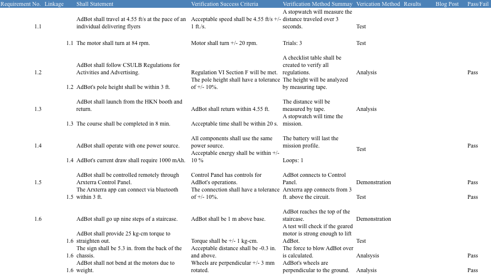
| Requirements from Spring 2016 Wednesday | Requirement Evaluation Rubric Number | ||||||||
| 1 | 2 | 3 | 4 | 5 | 6 | 7 | 8 | 9 | |
| Modifications to RoFi shall not exceed $320 | Y | N | N | N | N | N | Y | Y | Y |
| RoFi shall acknowledge and avoid objects within 3 feet | Y | Y | Y | N | Y | Y | N | Y | Y |
| RoFi shall traverse carpet, linoleum tile, and metal surfaces | N | Y | Y | N | Y | Y | Y | Y | Y |
| RoFi’s runtime shall be greater than 15 minutes | Y | Y | Y | N | Y | Y | Y | Y | Y |
| RoFi shall cross over a threshold, at approximately a 45° angle and a height of 2 cm | Y | Y | Y | N | Y | Y | Y | Y | Y |
| RoFi shall ascend an incline that is initially an 8° slope which then decreases to a 6° slope | Y | Y | Y | N | Y | Y | Y | Y | Y |
| RoFi shall complete the figure 8 obstacle course through the Arxterra Application during finals week (Monday, May 9 – Saturday, May 14, 2016) | Y | Y | Y | N | Y | Y | Y | Y | Y |
| Vision shall be provided through the on board phone | N | Y | Y | N | Y | N | N | Y | Y |
Section 3: Requirements
-Gifty Sackey (Project Manager)
Spring 2016 New Requirements: Level 1
- The Biped will be finished by the 9th of December, 2016 as designed in the CSULB calendar to correspond with the duration of the EE 400D class.
http://web.csulb.edu/~hill/ee400d/F’16%20Syllabus.pdf
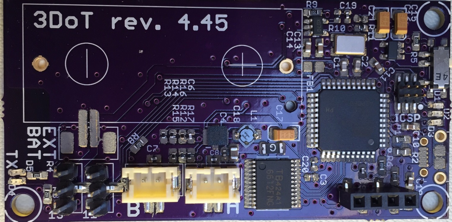
- Shall use one 3Dot board embedded system.
http://web.csulb.edu/~hill/ee400d/F’16%20Project%20Objectives%20and%20Mission%20Profile.pdf
- Shall use one custom SMD I2C shield.
http://web.csulb.edu/~hill/ee400d/F’16%20Project%20Objectives%20and%20Mission%20Profile.pdf
- The BiPed shall participate in an end of semester (December 9th, 2016) game where the BiPed’s goal is to outrun Velociraptor out of the arena with Goliath serving as its “eyes.”
http://web.csulb.edu/~hill/ee400d/F’16%20Project%20Objectives%20and%20Mission%20Profile.pdf
- The BiPed shall use two DC motors to control walking movement of two legs. The choice of the DC motor will be compatible with the 3DOT board.
- The BiPed shall walk statically and should demonstrate dynamic walking over flat, inclined, and declined surfaces for the entire duration of the game without falling over.
- “Control of the walking robots will use the Arxterra Android or iPhone application operating in RC mode”
http://web.csulb.edu/~hill/ee400d/F’16%20Project%20Objectives%20and%20Mission%20Profile.pdf
- The BiPed should be able to turn left and right at a maximum of 90 degrees at a time.
- The BiPed should be able to maneuver around the arena and should avoid collisions with surrounding objects.
System/Subsystem (Level 2)
– Brandon Perez (Missions, Systems and Test)
- Should use four ultrasonic sensors to support the BiPed in preventing numerous collisions into surrounding objects. Refer to requirement 9, level 1.
Quantitative: four ultrasonic sensors.
Verifiable: Through the use of ultrasonic sensors, the BiPed should be able to detect nearby obstacles such as walls, and react accordingly so as to not run into these objects.
Realizable: The BiPed should have one sensor on the four “faces” of the robot: one on front, one on back, one on each side. The BiPed should be able to be aware of its environment in all four directions.
2. BiPed will have a Bluetooth v 4 .0 BLE Transceiver integrated circuit that will be able to communicate with the class website of Arxterra. Refer to requirement 7, level 1.
Quantitative: The BiPed should use one Bluetooth v 4.0 BLE Transceiver.
Verifiable: The BiPed will be controllable through the use of the Arxterra Android or iPhone application.
Realizable: The 3Dot Board will utilize the a Bluetooth v 4 .0 BLE Transceiver to communicate with the Arxterra application to be remote controlled.
3. The 3Dot board shall be powered by a single CR123A 3.7V 650mA rechargeable Li-ion battery. A 9V battery will be used to amplify the 3Dot board’s signals. Refer to requirement 2 and 4, level 1.
Quantitative: The 3Dot Board will use a single CR123A 3.7V 650mA battery and one 9V battery will be used as an external power source.
Verifiable: Through the use of the CR123A battery to power of the 3Dot Board the 3Dot Board’s 5V turbo boost and dual DC motor driver should power the 1.5V-9V DC Motors. The 9V battery will be used to amplify the 3Dot Board’s 3.7V signals to drive the 4.8V servo motors.
4. The Biped will use 2 DC motor to control its main walking motion. Refer to requirement 5, level 1.
Quantitative: The BiPed will use two DC motors for walking.
Verifiable: The Biped should be able to walk with the use of two DC motors.
Realizable: A DC motor will be placed in each leg to drive the walking motion
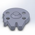
5. The Biped should use one wheel attached to one motor on each foot to execute the left and right turns. Refer to requirement 8, level 1.
Quantitative: The Biped should use one wheel attached to one motor on each foot (two wheels in total total).
Verifiable: The Biped’s wheels will be tested to ensure that it successfully turns left and right.
Realizable: A wheel on the side of the foot running clockwise or counterclockwise will help drag the feet and therefore position the Biped into the desired angle it wants to face when performing a turn.
6. The I2C shield will utilize 4-pin connectors as well as a four pin cable assembly to connect the four ultrasonic sensors via the I2C interface. Refer to requirement 3, level 1.
Quantitative: 4-pin connectors, four pin cable, four ultrasonic sensors
Verifiable: An ultrasonic sensor would be tested to ensure proper communication with the I2C interface
Realizable: The 4 ultrasonic sensors in each face of the BiPed (90 degrees apart) will help ensure the BiPed or the user has awareness of its surroundings.
7. Biped should use a gyroscope as a sensor to determine its position with respect to the ground and shift center of mass in front of it or behind it when walking on inclined or declined surfaces respectively. The MPU-6050 (Gyroscope + accelerometer) should be used since it was implemented by previous BiPed projects and test software is readily available. Refer to requirement 6, level 1.
Quantitative: Rotating gears at the hips will be 180 degrees out of phase
Verifiable: The BiPed should have the center of mass shifted from one foot to the other foot as a result of the hip placement of each leg being out of phase by 180 degrees during the gear rotation at the hips.
Realizable: Shifting the weight over one foot to the other will help ensure our BiPed is stable and balanced at all times during the complete walking cycle on both flat, inclined, and declined surfaces.
Section 3: Design Innovation
– Gifty Sackey (Project Manager)
The brainstorming and brain writing exercise mainly focused on answering three main problems we needed to consider when implementing and building the Biped. Among the problems we had to consider, was for the Biped to be able to maintain balance, while walking on bumpy terrain and inclined planes; the biped should be able to turn left and right and lastly the biped must be able to outrun its opponents. In completing our brainstorming requirements, we used the attributes listing, dunker diagram models and lateral thinking methods.
System/Subsystem (Level 2)
- Should use four ultrasonic sensors to support the Biped in preventing numerous collisions into surrounding objects. Refer to requirement 9, level 1.
Quantitative: four ultrasonic sensors.
Verifiable: Through the use of ultrasonic sensors, the Biped should be able to detect nearby obstacles such as walls, and react accordingly so as to not run into these objects.
Realizable: The Biped should have one sensor on the four “faces” of the robot: one on front, one on back, one on each side. The Biped should be able to be aware of its environment in all four directions.
2. BiPed will have a Bluetooth v 4 .0 BLE Transceiver integrated circuit that will be able to communicate with the class website of Arxterra. Refer to requirement 7, level 1.
Quantitative: The Biped should use one Bluetooth v 4.0 BLE Transceiver.
Verifiable: The Biped will be controllable through the use of the Arxterra Android or iPhone application.
Realizable: The 3Dot Board will utilize the a Bluetooth v 4 .0 BLE Transceiver to communicate with the Arxterra application to be remote controlled.
3. The 3Dot board shall be powered by a single CR123A 3.7V 650mA rechargeable Li-ion battery. A 9V battery will be used to amplify the 3Dot board’s signals. Refer to requirement 2 and 4, level 1.
Quantitative: The 3Dot Board will use a single CR123A 3.7V 650mA battery and one 9V battery will be used as an external power source.
Verifiable: Through the use of the CR123A battery to power of the 3Dot Board the 3Dot Board’s 5V turbo boost and dual DC motor driver should power the 1.5V-9V DC Motors. The 9V battery will be used to amplify the 3Dot Board’s 3.7V signals to drive the 4.8V servo motors.
4. The Biped will use 2 DC motor to control its main walking motion. Refer to requirement 5, level 1.
Quantitative: The Biped will use two DC motors for walking.
Verifiable: The Biped should be able to walk with the use of two DC motors.
Realizable: A DC motor will be placed in each leg to drive the walking motion
5. The Biped should use one wheel attached to one motor on each foot to execute the left and right turns. Refers to requirement 8, level 1.
Quantitative: The Biped should use one wheel attached to one motor on each foot (two wheels in total total).
Verifiable: The Biped’s wheels will be tested to ensure that it successfully turns left and right.
Realizable: A wheel on the side of the foot running clockwise or counterclockwise will help drag the feet and therefore position the Biped into the desired angle it wants to face when performing a turn.
6. The I2C shield will utilize 4-pin connectors as well as a four pin cable assembly to connect the four ultrasonic sensors via the I2C interface. Refer to requirement 3, level 1.
Quantitative: 4-pin connectors, four pin cable, four ultrasonic sensors
Verifiable: An ultrasonic sensor would be tested to ensure proper communication with the I2C interface
Realizable: The 4 ultrasonic sensors in each face of the BiPed (90 degrees apart) will help ensure the BiPed or the user has awareness of its surroundings.
7. Biped should use a gyroscope as a sensor to determine its position with respect to the ground and shift center of mass in front of it or behind it when walking on inclined or declined surfaces respectively. The MPU-6050 (Gyroscope + accelerometer) should be used since it was implemented by previous BiPed projects and test software is readily available. Refer to requirement 6, level 1.
Quantitative: Rotating gears at the hips will be 180 degrees out of phase
Verifiable: The Biped should have the center of mass shifted from one foot to the other foot as a result of the hip placement of each leg being out of phase by 180 degrees during the gear rotation at the hips.
Realizable: Shifting the weight over one foot to the other will help ensure our BiPed is stable and balanced at all times during the complete walking cycle on both flat, inclined, and declined surfaces.
Section 3: Design Innovation
The brainstorming and brain writing exercise mainly focused on answering three main problems we needed to consider when implementing and building the Biped. Among the problems we had to consider, was for the Biped to be able to maintain balance, while walking on bumpy terrain and inclined planes; the biped should be able to turn left and right and lastly the biped must be able to outrun its opponents. In completing our brainstorming requirements, we used the attributes listing, dunker diagram models and lateral thinking methods.
Section 4: Systems/Subsystem Design
- Product Breakdown Structure Refer to : http://web.csulb.edu/~hill/ee400d/Lectures/Week%2004%20Modeling/e_Product%20Breakdown%20Structure.pdf
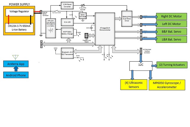
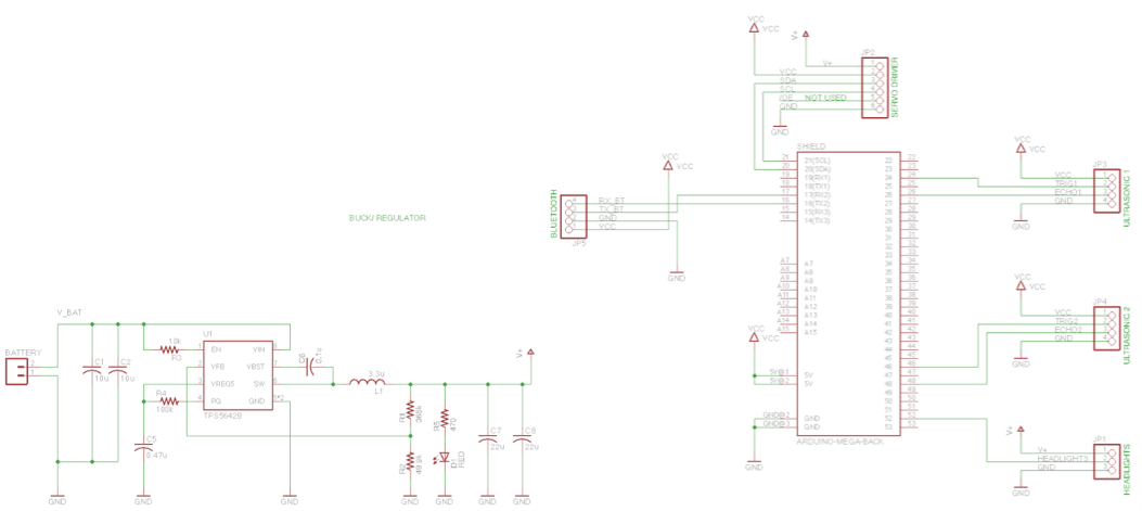
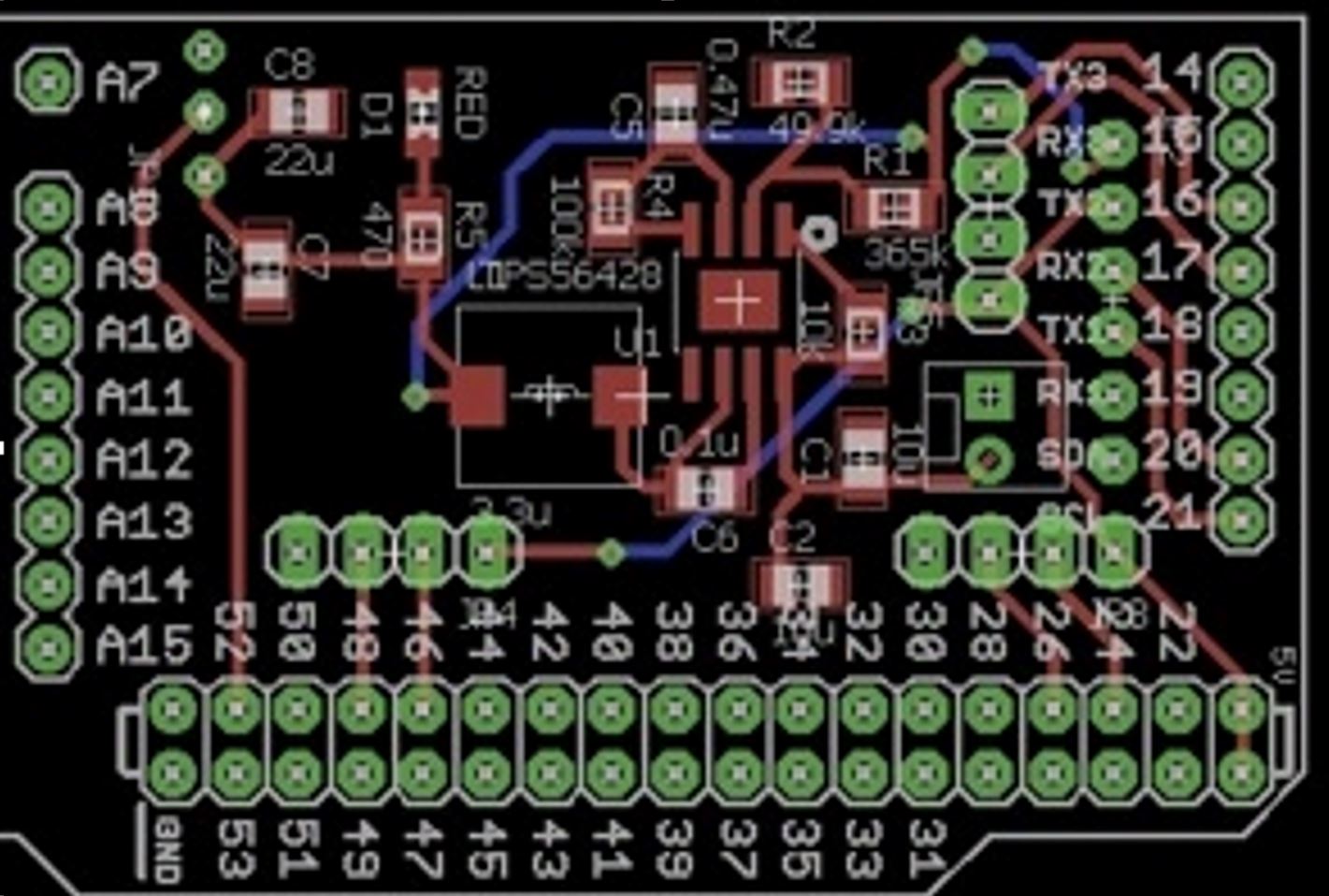
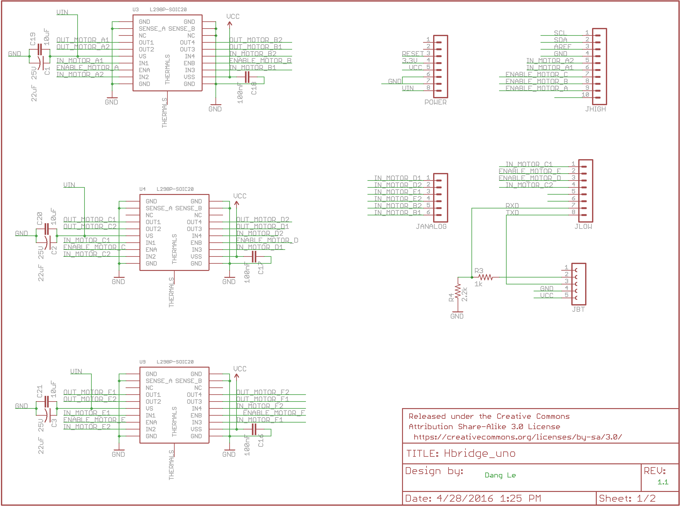
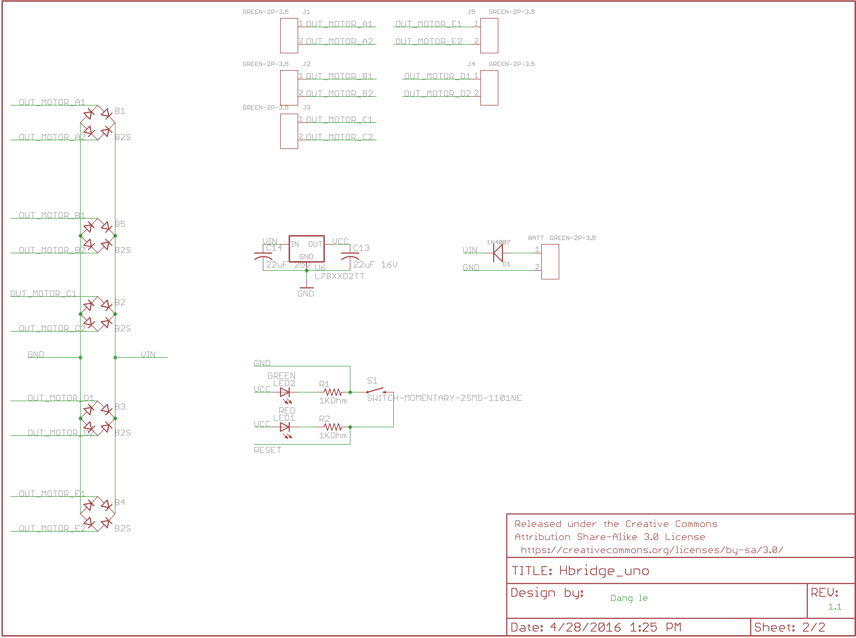
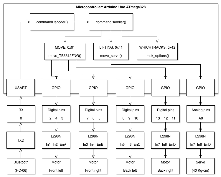
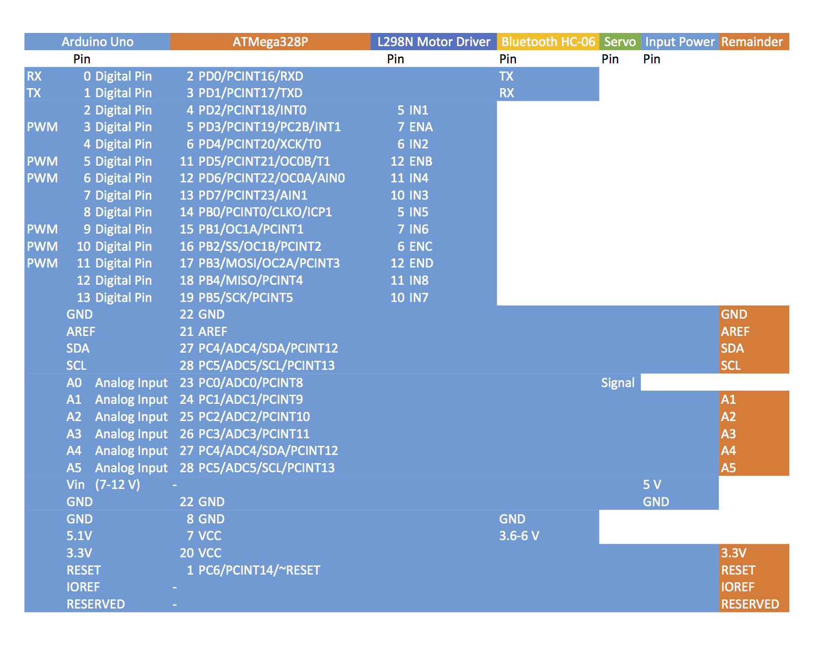
Section 5: Electronic System Design
Brandon Perez (Mission, Systems and Test)
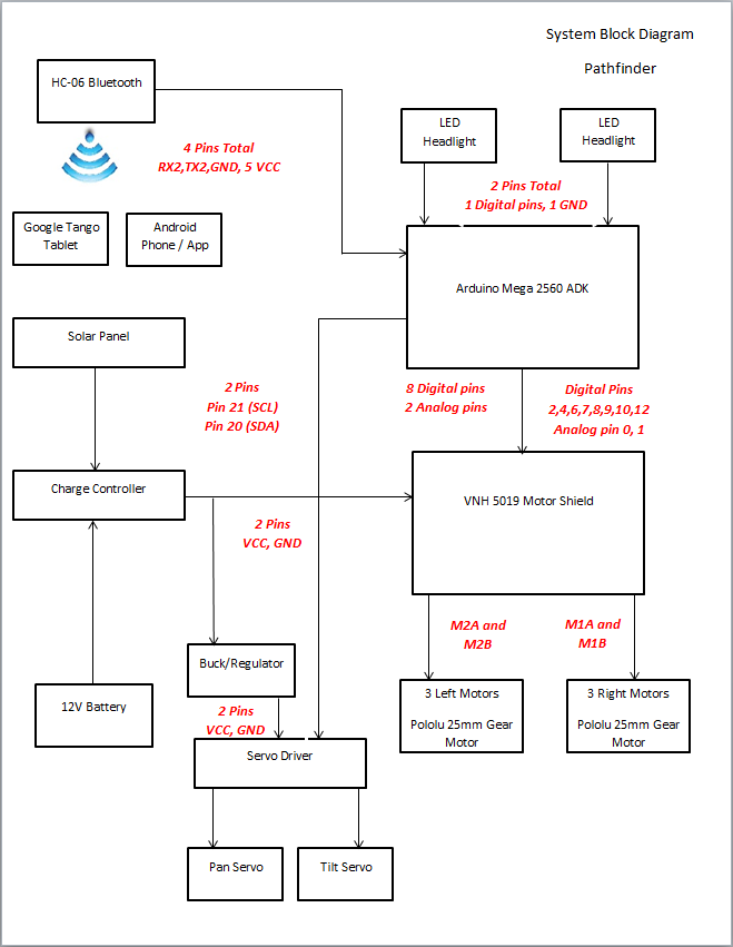
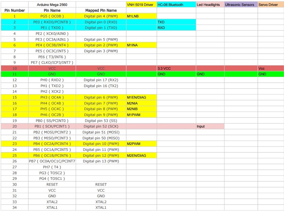
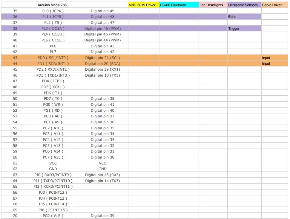
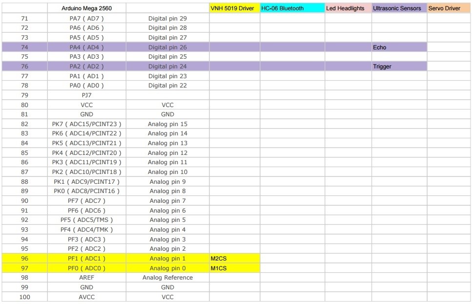
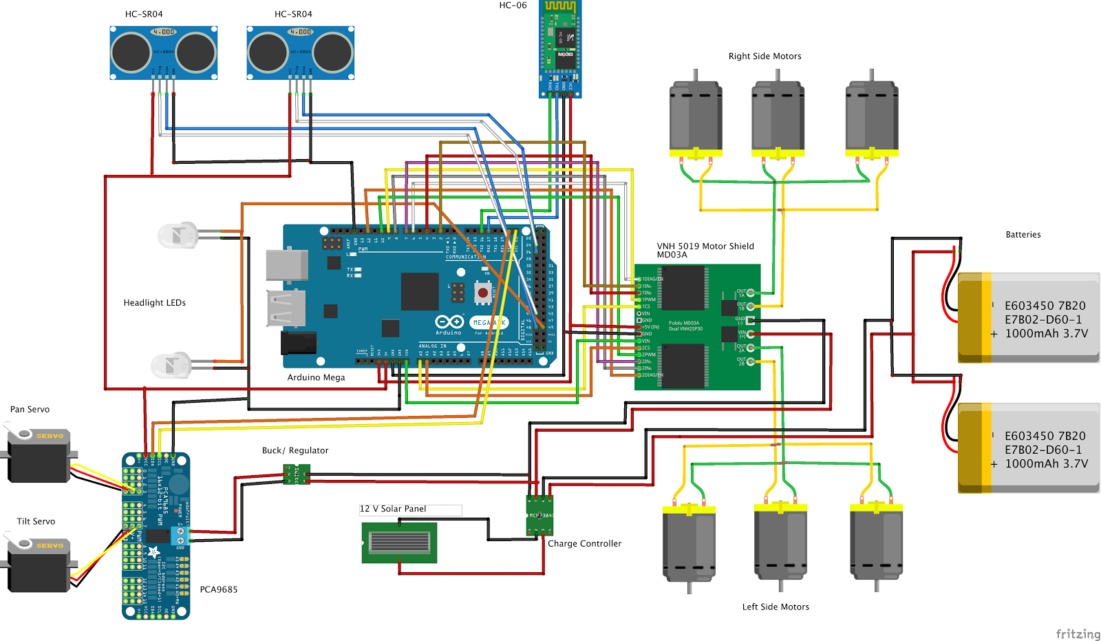
- System Block Diagram
- Fritzing diagrams
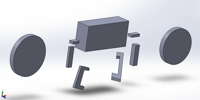
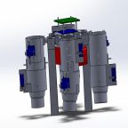
Section 6: Mechanical Design
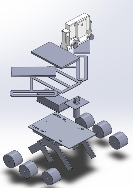
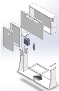
3D mechanical rendering of the system with subassemblies clearly identified (exploded view of the system)
- Descriptions of the subsystems, their interfaces and requirements
Section 7: Design and Unique Task Descriptions
Subsystem Descriptions (Ryan Daly – Electronics Engineer)
- Electronic components will be sourced from distributors in the U.S. with quantity already in stock to receive components promptly to begin construction as soon as possible.
- Wireless control of the Biped will be done using the Arxterra app and a Bluetooth module connected to our 3Dot Board. This includes walking, stopping, and turning the Biped in RC mode.
- The Bluetooth module will be chosen to have a supply voltage of 3.3V per the 3Dot Board’s voltage capacity.
- The ultrasonic sensors will be chosen to be compatible with the 3Dot Board’s I2C interface and power capabilities.
- A gyroscope sensor will be chosen to be compatible with the 3Dot Board’s I2C interface and power capabilities.
- The DC motors will be chosen to be compatible with the 3Dot Board’s power capabilities.
- The servo motors will be chosen to be compatible with the 3Dot Board’s power capabilities.
- Power supplies will be chosen so that the robot can operate for at least 30 minutes.
- Power supplies will be designed to supply the correct voltage to each component.
http://web.csulb.edu/~hill/ee400d/F’16%20Project%20Objectives%20and%20Mission%20Profile.pdf
Subsystem Tasks
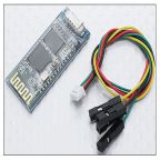
- Bluetooth Module
Subsystem Description
Wireless control of the Biped will be done using the Arxterra app and a Bluetooth module connected to our 3Dot Board. This includes walking, stopping, and turning the Biped in RC mode.
Subsystem Task
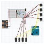
Find a Bluetooth module that is compatible with the 3Dot Board that will allow for communication between it and the Arxterra app.
Design Process
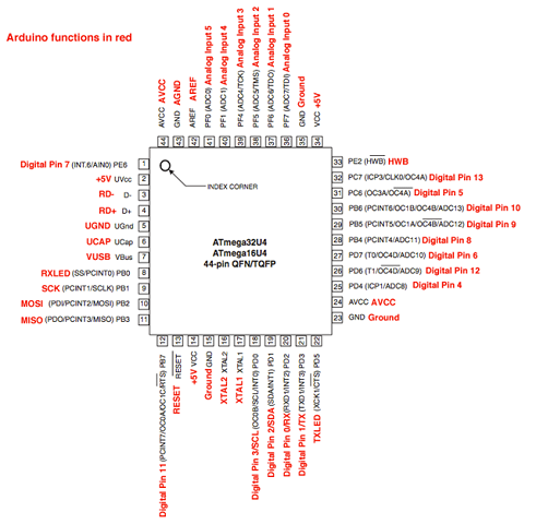
The 3Dot Board supports the use of a Bluetooth Module to communicate wirelessly with the Arxterra App. The ATmega 32U4, which is what controls the 3Dot board, has two pins for controlling a Bluetooth module: RXD (Digital Pin 2) and TXD (Digital Pin 3). Therefore, we are looking for a Bluetooth module with 4-pins (RS232 interface): Vcc, Gnd, RXD, and TXD. Vcc is something to keep in mind since our 3Dot Board only outputs 3.3V. Therefore, our Bluetooth module must either be compatible with 3.3V or we must create another power supply circuit and tap that voltage to power the module.
Previous semester’s Goliath, who also used the 3Dot board for their design, used the HC-06 Bluetooth Module. Pathfinder used this module also. This device is an acceptable choice for this project. This module only requires 3.3V-6V for operation, so it would work great with the 3Dot’s on board power supply. It also supports the 4-pin serial interface we are looking for. Furthermore, this module is cost effective at ~$8.99 and provides coverage for up to 30ft.
Testing
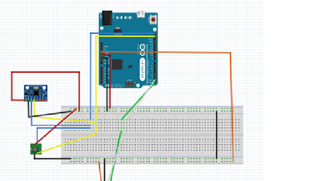
A test should first be conducted using an Arduino and our preferred Bluetooth module while we wait for or 3Dot board’s production to familiarize ourselves with the method of Bluetooth communication. The test should include functionality at 3.3V since that is what our 3Dot board will supply, as well as effective communications at distances up to 30ft.
- https://www.olimex.com/Products/Components/RF/BLUETOOTH-SERIAL-HC-06/resources/hc06.pdf
- https://www.arxterra.com/3dot/
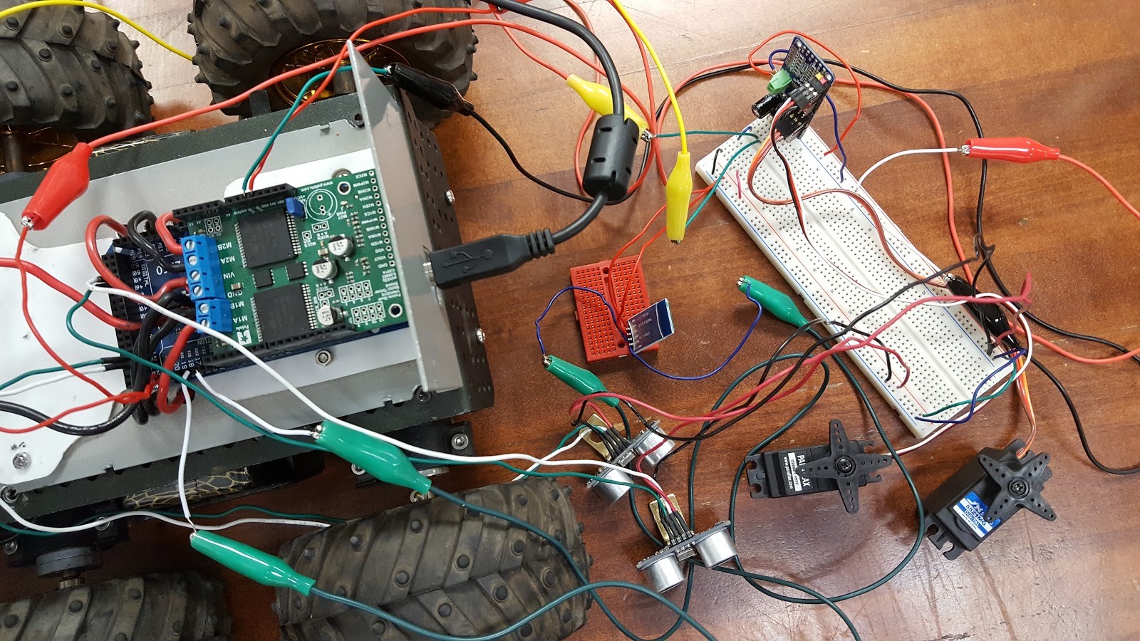
- Ultrasonic Sensors
Subsystem Description
Ultrasonic sensors will be used to detect the Biped’s surrounding environment.
Subsystem Task
The ultrasonic sensors will be chosen to be compatible with the 3Dot Board’s I2C interface and power capabilities.
Design Process
Four ultrasonic sensors will be placed on each “face” of the biped: one on the front, one on the back, and one on each side. These ultrasonic sensors should utilize the I2C interface.
Devantech SRF02 Low Cost Ultrasonic Range Finder is a good option. The cost is relatively low ($13) compared to other similar I2C ultrasonic sensors starting in the $20s. This sensor can detect ranges from 15cm to 6m which is comparably better than the cheaper HC-SR04 which can only detect up to 500 cm. One thing to keep in mind is that the SRF02 requires a supply voltage of 5V and should not exceed 5.5V, so we should route the 5V power supply on our shield to power this sensor.
Testing
The ultrasonic sensor will be tested to be sure that the servos respond quick enough that our robot will come to a complete stop or avoid obstacles, without falling over, when detected.
- http://www.robotshop.com/media/files/pdf/datasheet-sen026.pdf
- http://www.robotshop.com/media/files/pdf/devantech-srf02-specifications.pdf
- Gyroscope Sensor
Subsystem Description
A Gyroscope Sensor will be used to detect tilting of the Biped so that it can balance itself on inclined planes.
Subsystem Task
A gyroscope sensor will be chosen to be compatible with the 3Dot Board’s I2C interface and power capabilities.
Design Process
A gyroscope sensor will be located at the torso of the Biped and should have an I2C interface to connect with the 3Dot Board’s pcb shield. The gyroscope will work to detect tilts that the Biped will encounter, which could either be from being pushed by an external force or by walking up inclined planes. This will provide feedback to the microcontroller to stabilize our robot.
The MPU-6050 requires 2.375V-3.46V to operate and has an I2C interface as well, which would make this sensor appropriate for use on our robot.
Testing
The gyroscope sensor should be tested such that when a forward tilt is experienced, the servo motors that will be located at the ankles of the robot will turn so that the feet will tilt forward for the Biped to balance. Furthermore, if the sensor detects a backwards tilt, the servo motors will tilt the feet backwards to balance.
- DC Motors
Subsystem Description
Four DC motors will be used on the Biped: two at the hips to drive the walking motion and two at the feet to drive the turning motion.
Subsystem Task
DC motors will be chosen to be compatible with the 3Dot’s onboard dual DC motor drivers. Since the 3Dot board currently only supports 2 DC motors we must be able to generate our own circuit on our shield that can drive two more DC motors.
Design Process
Two DC Motors at the hips will spin the gears that will drive the walking motion. This method will shift the center of mass from left to right to allow for walking and eliminate the need of a servo motor at the hips to shift the hips left and right. These two DC motors will be driven by the TB6612FNG Dual DC Motor Drive located on the 3Dot Board. The DC motors will be rated to operate at 5V since the 3Dot Board supports a 5v Turbo Boost for driving DC motors.
The Biped will use two DC motors located at its feet to turn left and right. We have already used up the two DC motor drivers on the 3Dot board and we will need to use two more. To accomplish this, we can add a similar motor driver circuit that we see on the 3Dot board to our pcb shield. This would require us to tap the 5V power source on the shield to power a TB6612FNG Dual DC Motor Driver. This motor driver requires a supply voltage of 2.7-5.5V. The Motor Driver also uses six digital input pins to control the rotation of the motor. Our 3Dot board does not have any accessible DIOs so we will use TI P/N PCF8574 which is an IC chip with an I2C interface that outputs 8 DIOs. We will use these DIOs to control the TB6612FNG. This 8-Bit I/O Expander for the I2C-Bus requires 2.5-6.6V for operation so we will route the 5V power supply from our shield to power this IC chip.
Testing
The DC motors should be tested such that they provide torque even when under load, showing that they can move our robot.
- http://www.ti.com/product/PCF8574
- http://www.karlssonrobotics.com/datasheets/Robotics/TB6612FNG.pdf
- https://www.arxterra.com/3dot/
- Servo Motors
Subsystem Description
The Biped will use two servo motors: one at each foot to tilt its feet forwards and backwards to stabilize itself when walking up or down inclined/declined planes.
Subsystem Task
Servo Motors must be chosen to either be compatible with the 3Dot Board’s onboard 3.7V servo dual servo motor driver ports.
Design Process
The 3Dot board supports 2 servo motors, capable of operating both motors at 3.3V. The problem is that most servo motors are operational at around 4-6V. To overcome this problem, we will route the pins for the servo motors to our shield which will use a 9V battery and an LM7805 voltage regulator to power the servo. While Vcc will require 5V, a 3.3V PWM signal will be sufficient to drive the servo.
Testing
The servo motors will be testing to ensure that a Vcc of 5V and a 3.3V PWM signal will be sufficient to drive them since this is what our design calls for. Furthermore, as explained above, we will need to test these servos with other sensors to make sure that they respond to the feedback from the sensors.
- http://media.digikey.com/pdf/Data%20Sheets/Adafruit%20PDFs/2201_Web.pdf
- https://www.arxterra.com/3dot/
- http://webhttp.csulb.edu/~hill/ee400d/Technical%20Training%20Series/3DoT%20Datasheets/Block%20Diagram.pdf
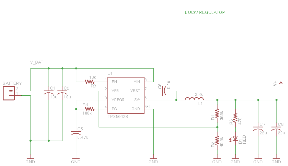
- Power Supply
Subsystem Task
The Biped’s power supplies must be chosen such that each component will receive the proper power for operation.
Design Process
The 3Dot Board has two battery connection points. The first battery holder supports a CR123A 3.7V 650mA rechargeable Li-ion battery. The second is an external battery connector where we will connect a second 3.7V battery which, when looking at the block diagram for the 3Dot board, shows that these batteries will be connected in parallel. Choosing a 3.7V battery as the second batter is important for a few reasons. First, when connecting batteries in parallel, they should always be the same voltage, especially if the lower voltage battery is rechargeable. The battery with a higher voltage will charge the battery with a lower voltage, and with no protection circuit for charging the battery, it could overcharge and become damaged. So then, why use another battery at all? If we use two 3.7V batteries in parallel, we can increase the available current and the milliamp-hours. Increasing the available current is useful because we are feeding this 3.7V into a 2.5W boost converter. This boost converter will draw a higher current at a lower voltage to convert this power into a higher voltage with a lower current. It does this to boost the incoming 3.7V to about 5V to power the TB6612FNG Dual DC Motor Driver.
A second power source will exist on the pcb shield that will consist of a 9V battery and an LM7805 voltage regulator to generate a 5V power supply for the components in our design that are not compatible with 3.3V and need 5V to operate.
Testing
Testing each component with the exact power that we will be supplying it with our 3Dot board will be crucial in determining the functionality of each component in our finalized system.
- http://webhttp.csulb.edu/~hill/ee400d/Technical%20Training%20Series/3DoT%20Datasheets/Block%20Diagram.pdf
- http://cdn.sparkfun.com/datasheets/Tools/NCP1402-D.pdf
- https://www.arxterra.com/wp-content/uploads/2016/04/FullSizeRender-1.jpg
- https://www.youtube.com/watch?v=wJU7AJgERG8
Manufacturing Engineer Research
(Manufacturing Engineer -Ijya Karki)
Review of Literature
Reviewing old material provides a greater insight on why past Biped projects were successful or not successful. My focus of reviewing old material was on the different Manufacturing complications and successes to guide how our group could tackle various problems.
3D Printing
Final Project Debriefing, December 20, 2013 https://www.arxterra.com/final-project-debriefing/
3D Printing Versus Molding, April 28, 2015 https://www.arxterra.com/3-d-printing-versus-molding/
Fall 2013 documented the successful, precise 3D printed parts. They predicted a long lifespan of the printed plastic components. The main issues that were encountered occurred later in the project when additional modified designs of parts were created. They had trouble with screwing the components together and the fit of the old and new parts.
Spring 2015 documented the reasons that 3D printing was chosen. The main reasons were because 3D printing is customizable, and cheap. They specified renting a machine for 30$ (not including the cost of plastic.) The main con the team expressed about 3D printing is the limitation that the material must be plastic. The team explored the option to mold materials. Pros of molding is the strength of the molded object. Cons of molding is that it isn’t as customizable as 3D printing, and it costs a lot.
This team faced problems after 3D printing. The manufacturing engineer forgot to allow room to loop wires through the different brackets that were created.
Materials
Material Choice, April 28, 2015 https://www.arxterra.com/material-choice/
ABS or PLA? Choosing The Right Filament http://makezine.com/2014/11/11/abs-or-pla-choosing-the-right-filament/
Spring 2015 documented the various plastics considered for 3D printing. The group chose to go with PLA plastic because it is lightweight and cheap. Some noted disadvantage of PLA was limited flexibility, and the fact that it is weaker than molded plastic. Advantages of ABS plastic is it is more flexible, and it has as higher temperature resistance than PLA. Some disadvantages of ABS is that it is harder to 3D print and more time consuming. Advantages of molded standard plastic is that it has the strongest bond compared to PLA and ABS. Disadvantage of standard plastic is price and harder to modify parts than 3D printing.
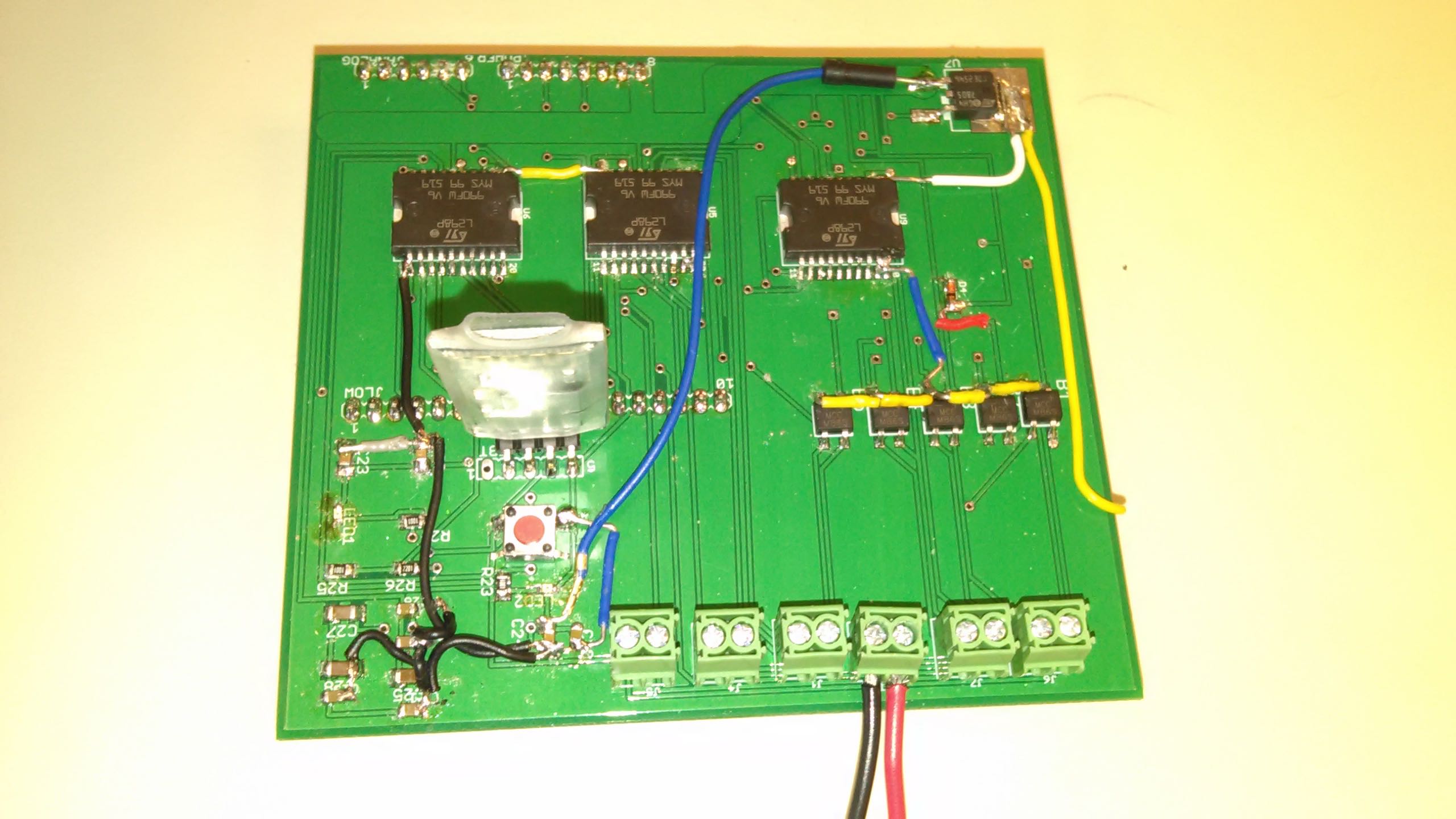
PCB Layout
PCB Design, November 18, 2014 https://www.arxterra.com/pcb-design/
Spring 2016 RoFi PCB Layout, May 1, 2016 https://www.arxterra.com/spring-2016-rofi-pcb-layout/
Fall 2014 documented the custom design of their PCB. Manufacturing completed the soldering of the board. They highlighted their PCB layout as one of the successes of the semester. It performed the as anticipated.
Spring 2016 provides a list of steps to make sure that the group’s created PCB design is compatible with the Fabrication House DRC check. The documentation also provides steps on converting file type to gerber files. This group’s project summary explains how the gerber files are given to the president who then orders the board and the components. It took a week and a half to get all the components. The Manufacturing Engineer is responsible to solder these parts together.
Ideas and Advice
Final Documentation MicroBiPed, May 16, 2015 https://www.arxterra.com/final-documentation-microbiped/
Fall 2013 suggested to increase the size of any components around the chosen motor to allow room for the motor to spin.
Fall 2014 suggested to prototype the Biped before printing the actual parts. Avoiding 3D printing for the prototype is possible, we would just have to explore our options. Prior to assembling the custom PCB design,, draw out the anticipated look of the board. They faced issues with connecting female pins to the PCB. They ended up using jumper wires to connect the ground pin.
Spring 2016 suggests to purchase parts after the approval of the customer. Confirm that the 3D material is the best type for the project before committing to the material. Document all interaction with the customer to avoid confusion in the future regarding things that were asked for. If values change make sure to update documentation or make note of the change.
Review of Old Requirements
Requirements, April 21, 2015 https://www.arxterra.com/requirements/
Examining past level 1 requirements that pertain to manufacturing
| Requirement Evaluation Rubric Number | |||||||||
| 1 | 2 | 3 | 4 | 5 | 6 | 7 | 8 | 9 | |
| Design a new custom PCB (Fall 2014) | Y | Y | Y | N | Y | N | – | N | Y |
| The μBiPed must weigh no more than 1 kilogram in order to facilitate the miniaturized size of the μBiPed. Otherwise, if the μBiPed is too heavy the project may not be realizable (Spring 2015) | Y | N | Y | N | Y | N | – | N | Y |
| The μBiPed must be miniaturized as is dictated by its own name, size 7 inches (Spring 2015) | Y | Y | Y | N | Y | N | – | N | Y |
Examining past level 2 requirements that pertain to Manufacturing
| Requirement Evaluation Rubric Number | |||||||||
| 1 | 2 | 3 | 4 | 5 | 6 | 7 | 8 | 9 | |
| Manufacture Professional custom PCB to help alleviate any loose wires hanging on the robot and reduce weight distribution (Fall 2014) | N | Y | Y | N | Y | N | – | N | Y |
| In order to successfully miniaturize the μBiPed, micro-servos will be used. Type of micro-servos are MG92b after testing. The project must test the micro servos using SolidWorks or through math analysis in order to determine if micro servos provide enough torque to complete the project (Spring 2015) | N | Y | Y | N | Y | N | – | N | Y |
| Due to the miniaturization of the μBiPed, a PCB board will be fabricated that includes the wiring for the gyro, the Bluetooth IC, and the servo pins that will allow for the microcontroller to interface with the assembly (Spring 2015) | N | Y | Y | N | Y | N | – | N | Y |
| In order to traverse multiple surfaces the μBiPed’s legs must have some type of thread or rubber sole added to it (Spring 2015) | N | Y | Y | N | Y | N | – | N | Y |
| A lightweight material must be used for the frame in order to keep within the specific mass restrictions of the μBiPed; the type of material is PLA. Testing must be done as to whether or not the μBiPed can be made of plastic, or if a lighter material must be used (Spring 2015) | N | Y | Y | N | Y | N | – | N | Y |
Most of the listed requirements do not meet 1 of the rubric because they miss the quantitative requirement. Requirements that didn’t miss 2 of the rubric were placed in the wrong level of requirements. No requirements evaluated provide a link to source material, therefore they do not meet 4 of the rubric. No requirement needed equations which is 7 on the rubric. No requirement meet is formatted in the right language, thus it does not meet 8 on the rubric. Requirements that did not meet 9 had a requirement that could have been split up into two sections.
Fall 2016
Going through the old Biped blog posts, I got a clearer view about the complications past groups ran into. I was also able to determine what manufacturing strategies were most beneficial. By evaluating older requirements, I have a better understanding about how to continue with my subsystem requirements. First I will discuss the suggestions I have for the upcoming semester.
3D Printing
3D printing has been successful for the past semesters. I would suggest continuing forward with this method to produce parts of our robot. Cautionary facts to consider will be the time it takes to print, the spacing of material (or wires), and picking the right dimension of screws.
Materials
Due to the fact that we will be 3D printing our parts, we will have to use plastic. To keep the cost of our robot low, we could go with PLA.
PCB Layout
The main concern with the PCB layout is the ordering/arrival time of the product. I suggest to factor this time into the schedule.
Ideas and Advice
I would like to utilize the advice provided by past semesters as much as possible so that we can avoid as much problems as possible. I suggest creating 3D models of components while keeping in mind that we may need room to move or add wires. I suggest that we make as many sketches as possible to visualize our product before finalizing ideas. I also suggest checking up with the customer weekly to make sure that we are producing the product that the customer had in mind.
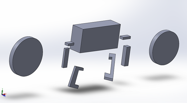
3D modeling
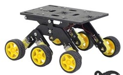
Wheels
Wheels added to the Biped will help the robot turn right and left. One foot will remain stationary on the the ground while the second foot will slightly be elevated in the air. The wheel attached to the foot that is still on the ground will rotate backwards and turn the biped in the direction of whichever foot is on the ground. For example, when the biped is on the left foot it will turn left and when the biped is on the right foot it will turn right.
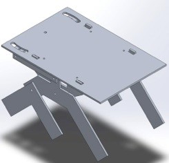
Body
The final body design dimension is yet to be finalized. However the body width will be larger than the body height. This goal is to keep the body close to the ground as possible.
Legs / Feet
The feet will be connected to the body through the leg parts. Although the final design dimensions have not been chosen, the feet itself will be larger than the width of the body to prevent it from loosing stability.


