By: Ayman Aljohani ( Project Manager)
Team members:
Ayman Aljohani (Project Manager)
Tae Lee ( Mission and Systems Engineer)
Kevin Moran (Electronics and control Engineer)
Jerry Lui (Manufacturing Engineer)
Executive Summary
Objective
The objective of the 3DOT Goliath is to design a small-scaled version of the Goliath Tank, as a toy, that meets the following
requirements: Safe: uses IR transmitter and receiver. Less than 6 hours printing time. Piloted via live cam on an Android phone. Low cost: should not exceed $80 total. Controlled by 3DOT board. Looks cool and inspired by the Goliath Tank. Periscope must be attached to an Android phone laying horizontally zero degree with the x-axis.
Mission Profile
The mission profile of this project is to play a “laser-tag” battle with the 3DOT Spider. Every hit will require a 5 second delay in between to avoid multiple tags. With each hit the buzzer will make a sound to indicate that it got hit. After receiving the third hit the robot will be disabled and play a short song afterwards. The game will take place in a 6 ft. x 6ft area on the linoleum floor. The maximum distance for detection from the detector will be 5 ft.
Mission Objective Update

Level 1 Requirements
- Laser tag game must be safe for children
- Uses IR transmitter and receiver to stimulate a game of tag
- Less than 6 hours printing time
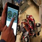
- Piloted via live cam on an Android phone
- Low cost: should not exceed $80 total
- Controlled by 3DOT board
- Looks cool and inspired by the Goliath Tank
- Periscope on an Android phone degree with the x-axis
Level 2 Requirements
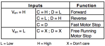
- The rover will be controlled by two individual DC motors (3-5V)
- Battery duration should last to the whole period of the battle 15 min
- Controlled via Bluetooth using an Android Device
- Print parts of rover individually
- LED will be used for a game of laser tag
- Laser sensors (on PCB) must be 3 inches
Preliminary Project Design Documentation found here
System Design
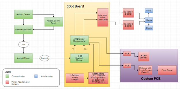
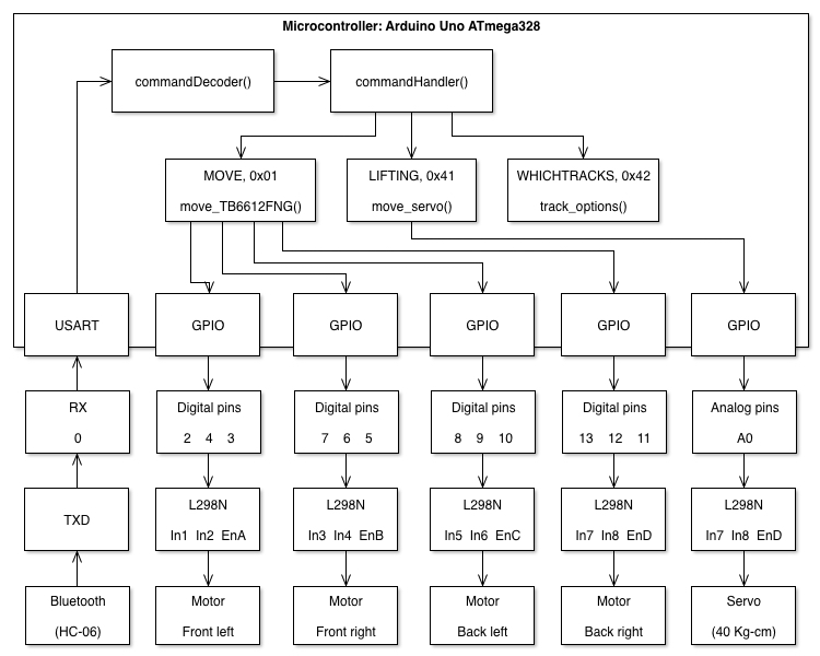
System Block Diagram

The figure below will show how each components on the Goliath will be connected and how they will interact with each other.
Experimental Results
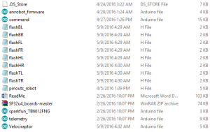
Uploading the Firmware onto the 3Dot Board
After assembling the 3Dot Board we need to program the ATMEL 32U4 chip by uploading a firmware. Without the firmware we will not be able to upload any programs onto the ATMEL 32U4. A detailed explanation will be provided by the following link: Upload Firmware
Troubleshooting the 3DoT Board
After assembling the 3Dot board I had to make sure that each component was soldered correctly. In addition, testing the motor driver by uploading a program using the Arduino IDE onto the 3Dot Board. To know more about the test procedure, check out the following link: 3Dot Board Troubleshooting
Arxterra Control Panel Test
To be able to use the Arxterra Control Panel from the website we had to perform a couple of tests. The test is to make sure that the communication between the android Arxterra application communicates with the Arxterra control panel (1) on the computer. To know how the test was implemented check the link: Arxterra Control Panel Test
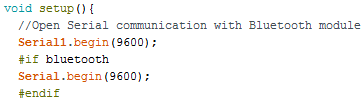
Bluetooth Module Test
Before we implement the Bluetooth module onto the Arxterra Firmware we had to perform a simple test to see how the Bluetooth module functions. The test will allow us to see the information we send from the android device using the BlueStick Control, which will than be displayed on the Arduino serial port. The link will provide a detailed explanation of the test performed: Bluetooth Module Test
3DoT Goliath DC motor trade-off study
In this post, it was my job to narrow down from a few DC motors to just two and do a trade-off study in order to figure out which one would work best. The motors were compared in regards to customer requirements. The motor chosen had to fit all customer requirements, including some requirements needed in order to make the project successful.
Motor trade-off study
Laser vs IR LED trade-off study
In the beginning of the semester, we began comparing two different method for meeting the project requirement of having a laser tag game. We tested both a laser and IR led with their respective receivers. The benefits of the laser were the range and low power consumption; the problem was the safety with using lasers. The IR LED was very safety to use, unfortunately the range was very low, as the light diffused. At this point we believed the laser would make the perfect candidate for the game.
Laser vs IR trade-off study
Progression of laser tag components
In this post I explain my reasoning in the progression of the different technologies we wanted to use to make the laser tag possible. The laser and IR emitter were giving me trouble in order to design the game. Another idea was to use a visible LED and turn that into brighter light using the same idea of a flashlight. Testing proved successful as I was able to increase the range, and maintain the safety. As it would turn out, the LED light would not a viable option either, yes be ready to have your ideas rejected often, that is life.
Progression of Laser tag components
Making laser tag possible: The Schmitt trigger
In this post I discuss why a Schmitt trigger is needed in order to make the laser tag game successful. Since I will be using an IR emitter/receiver, the signal output is analog which is very hard to control. By using the Schmitt trigger I am able to invert this signal and convert it to a single bit digital signal output, which we are able to monitor better.
Making Laser tag possible
Making laser tag possible: The receiver
By recommendation of my division manager, for the receiver we used an infrared transistor SPH 310 (Opto-semiconductor). In the post I include the analog voltages outputs using both Arduino plotter and monitor. You will find basic code to test the analog voltages as well as my EAGLE CAD drawing.
The Receiver
Making laser tag possible: The emitter
In this post I discuss the IR emitter, which is built by using a few resistors, an IR LED, and a 2n2222 NPN transistor. The calculation for the resistor that I have selected are provided. This emitter will be able to be controlled on/off by controlling the voltage that is sent to the base of the transistor. The EAGLE CAD schematic is also included.
The Emitter
Subsystem Design
Interface Definitions


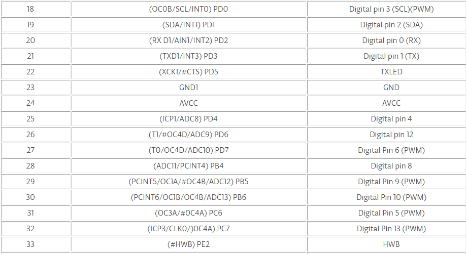
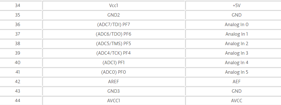
The following table will provide the pins for the Atmega32u4 Microcontroller 3Dot Board:
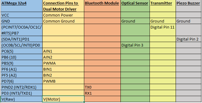
Now we will narrow down the number of pins we will be using on the Atmega32u4 Microcontroller:

CUSTOM PCB DESIGN
3DoT Goliath PCB Testing
Once the PCB was assembled by manufacturing engineer, it was my job to ensure it would work. With the help of the division manager, and systems engineer we were able to determine the problem. The blog post goes through our mistake and how we solved the problem, as well as a recommendation for when you have to design your PCB.
Custom PCB Design Testing
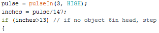
Making Laser Tag Possible: Extending the IR Range
With the PCB working correctly, I realized that the range was around 6-8 inches. That range needed to increase in order to make a more entertaining laser tag game. With the help of a lens and an online formula I tried to concentrate the IR LED in order to increase the range. Here you will find a very helpful formula that will help you with this problem.
Extending the IR range
The PCB Layout
In this blog post you will find the process I had to go through in order to finalize the final PCB layout. From the design on Fritzing, to testing the circuit, and finally designing it on Eagle CAD. All files have been provided by Eagle CAD. Pay attention to the Phoenix 254 connectors, as well as grounding everything to ensure your circuit works.
PCB Layout
PCB physical layout
For the PCB layout blog post I go detail on the methods and a few tips and tricks regarding the layout of the board and the usage of EagleCAD. The main thing to remember is the trace width guide. For boards that aren’t powering much (simple light show, 1 or 2 small motors) the trace width can be fairly thing but for anything that requires more power (over 500mA) one should consult the guide to properly determine the width otherwise it won’t be able to supply enough power.
Remember to manually layout your traces! The auto route is terrible.
PCB Physical layout
SMD Soldering
The SMD soldering blog is just quick tutorial on how to solder small IC’s and surface mount components. I’ve included a very good video on how to SMD solder using a hot air gun and soldering iron for the larger SMD components (0805 resistors, etc.)
Note: Due to an issue with embedding the video won’t play properly. Open it in another tab and you’ll be able to view it.
SMD Soldering
3DoT Board Fabrication:
The 3DoT Board was soldered by project manager and tested by System Engineer.
3DoT Board Fabrication
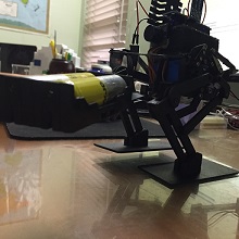
Hardware Design
Goliath Body dimensions
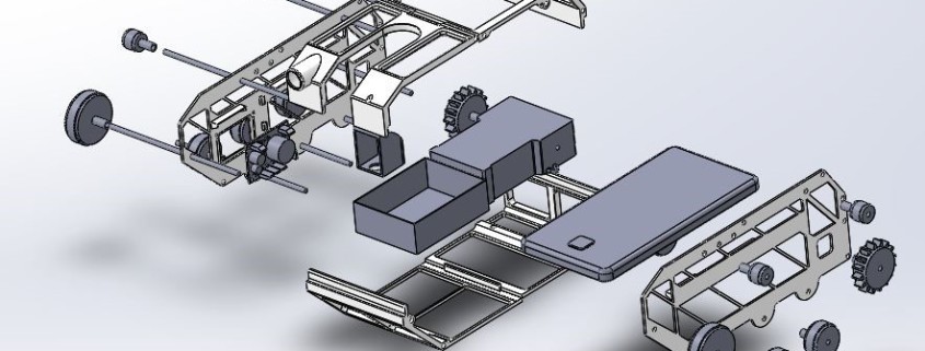
This blog was created to give a quick overview of our preliminary design and various features within Solidworks (filter types). Although this design was created before one of our manufacturing engineers had to drop the general dimensions remained the same. The body is still designed to house all of the components (3dot board or Arduino nano, battery box, motor cage, phone, etc.).
The filet options are mainly for aesthetic purposes. Instead of rounding off the corners of cutouts a conic rho profile can be used which generates a pointed, yet rounded, corner.
Preliminary Body Dimensions
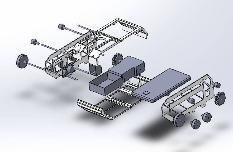
Final body redesign
Since the manufacturing engineer that was originally tasked to create the body had to drop the course, I had to redesign the body to meet the requirements set out from the beginning of the course.
This blog just briefly goes over what to be done and what compromises were made to meet the majority of the requirements (only one requirement was not fully met at 50% -> exact replica of Goliath tank).
Final Body Design
SOFTWARE DESIGN
Updated Laser Tag Communication System
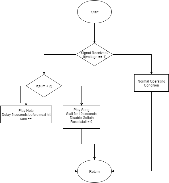
The new modified flow chart (shown below) will incorporate the new laser communication system. New features will include an automatic turn after receiving a single hit to avoid multiple hits in less than a second. In addition, to disabling the Goliath and playing a short song after the third hit.
The finalized flowchart for the laser communication system for the Goliath is shown below:

The arduino C++ code that will be implemented in reference to the flowchart on the Goliath will be available by following the link: Goliath-Arxterra Firmware
Making laser tag possible: Putting it all together
The final blog post in the sequence of making laser tag possible. Here you will find the final product of the emitter/ receiver combo. I have also included a flowchart showing exactly how our circuit will work. The circuit is to detect three different hits by an IR LED. After each hit a piezo buzzer will make a tone sound, after the third hit we play a melody and the rover is deactivated. The final code and output results are included.
Putting it all together
Arxterra Firmware Motor Control Modification Test
The 3Dot Board was not given at the time, so we had to use the Arduino Uno and the Arduino Motor Shield. The Arxterra Firmware that was given to use had the motor controls for the Sparkfun Pro Micro with the Dual Motor Driver. Hence, we had to make modifications to the firmware to work with the Arduino Uno and the Arduino Motor Shield.
3DoT Goliath IR Emitter/Receiver Code Test
The early stages of development of the laser tag system required research and testing. To see how IR worked we performed a basic test using IR Mid-Range Proximity Sensor (TSSP4P38) and a remote control (IR Emitter). Follow the link to see a detailed explanation of the testing procedure for the circuit setup and the code used to test the sensor.
Verification and Validation Test Plans
We will perform a verification on the requirements that was discussed by the customer. Each subsystem engineer will perform a verification test to verify that it meets level 1 and level 2 requirements. A verification document/verification matrix are given in order to verify each requirements.
In addition, a validation will be required to test the mission profile (rules of the game) by following a similar test plans as the verification. For validation we will validate the test plans using a validation document on how to perform the test and validation matrix to check off the validated requirement.
Project Overview
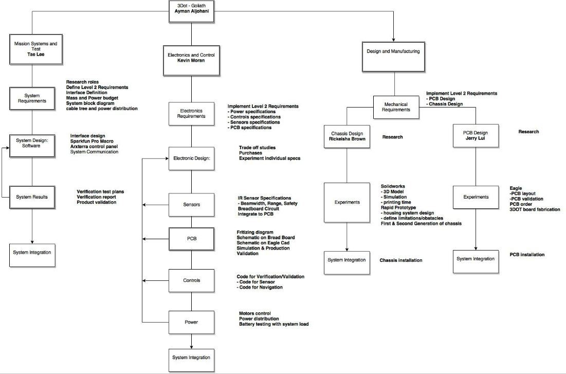
WBS:
The WBS has been updated after resources allocations, one of the manufacturing engineer was assigned to work on PCB layout, and the other one was responsible for chassis design. A link to the WBS is here

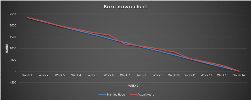
Burndown Chart:
This is our final Burndown chart
Here is a link to the Burndown chart

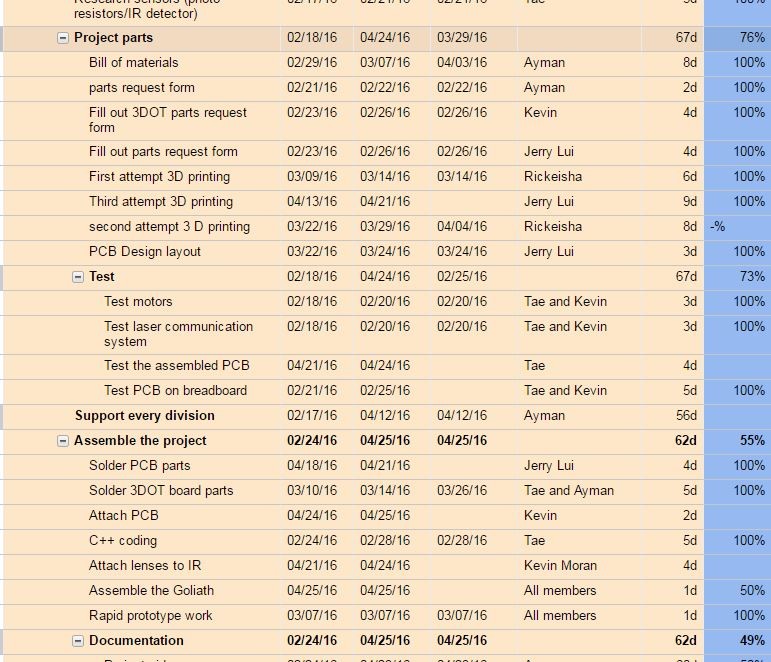
Project Schedule:
The project schedule is divided into two levels, high level requirement under “planning phase”, and level 2 requirements which is broken down to tasks. Project Schedule
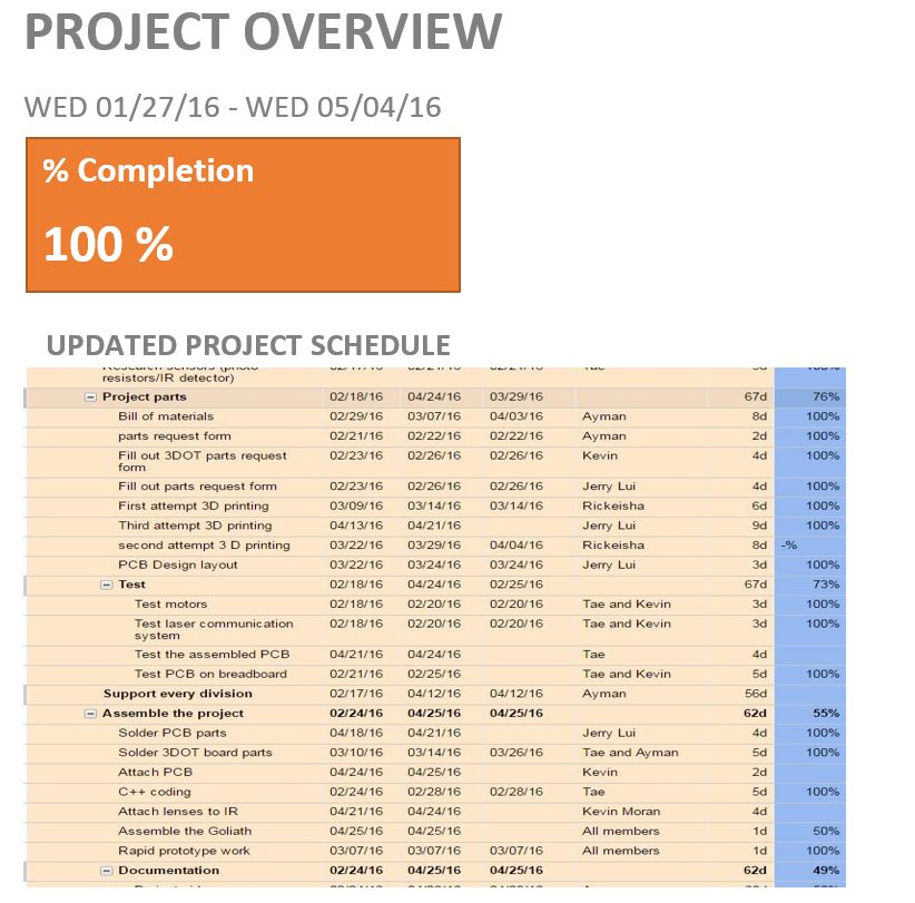
Here is a screenshot of the updated project schedule. The project percent completion is 100% .
The project schedule was created on a very useful tool, Smartsheet. Here is a link to full details blog post. Smartsheet .


Project Budgets:
One of level 1 requirements is budget. It is the project manager’s responsibility to keep track of budget, one way to do that is to have a parts request form. Any team member should fill out the request, print it out, sign it , and get the PM approval before proceeding with any purchase. Our actual project budget is $85
Here is a link to Parts Request Form.
Here is a link to Project Budget.
Mass Budget
Power Budget
Concluding Thoughts:
Suggested Practice:
As a project manager, I had to work closely with each division engineer, especially Systems Engineer. I learned a lot through this experience. In the beginning of the semester, we had to sit with customer, president, and student assistant to define level 1 requirement of the project. That process, iteration, is a continuous process in which a project manager verifies the customer’s requirements and provides options. The Goliath mission was to battle 3DoT Spider, thus it is important that both team work closely to define game rules and communications means between two robots. Also, another important thing is beam-width of IR, in our project we used IR, should be the same for a laser-tag game to be fun. The customer requirements will be very simple in terms of wording, but project manager and team should critically think of being creative thinking out of the box.
For a project to be completed in a timely manner, the team has to meet at least twice a week, one during regular class time, and another during the week. We had to meet three times a week to complete our project, twice on campus and once online. Communication between team member is highly important, so from the first meeting we decided to use Google Hangout app to communicate with each other.
Lesson Learned:
Preliminary Design Review, and Critical Design Review should have detailed information about the project. Project Manager should start preparing for CDR and PDR two weeks before the deadline.
Project video is a useful tool to promote the project, thus it is advised that Project Manager plan the video from the beginning of the semester by recording clips of the engineering method followed toward the final product.
Smartsheet was a powerful project management tool that helped me easily managed my team. At the same time, it is good platform for communication between team members to have discussions about certain task assignment or requirement clarification. I strongly encourage project managers to use it, here is some information about it.
Blog post is a good way to pass the knowledge to successors, therefore I encourage all team members to post on Arxterra regularly.
After all, this was a challenging experience that expanded my understanding of real world engineering problems.
Resources
- Project Video
- CDR Presentation for Goliath (Prezi)
- PDR Presentation for Goliath
- Project Schedule on Smartsheet
- Project Burndown
- Project Schedule on Google Spreadsheet
- Verification and Validation documents
- Solidworks Chassis File for Goliath
- Fritzing Files for Goliath
- EagleCAD Custom PCB Files for Goliath
- Burndown Excel File
- Arduino and/or C++ Code
- BOM
- Other Files (Parts Purchase Request) , Team Members Evaluation Rubric


