Rover Team Servo Holder and Mirror

By Vinh Kim, 3D Modeling and Manufacturing

Introduction:
Using SolidWorks, the Rover project manager Maxwell had requested me to design him a servo and mirror holder.

figure 1 

Figure 1: Servo holder

 figure 2

Figure 2: Mirror

figure 3 

Figure 3: Servo holder and mirror with cell phone.

How to use STL file cutting

By Vinh Kim, 3D Modeling and Manufacturing

Introduction:
To print out 3D materials, the Manufacturing Division Manager Ali Etezadkhah will provide his own 3D printer that can print 5 by 8 in parts. In some cases, the 3D printer cannot print larger parts because its size is too small. In order to cut down the size of the model, we have to use a program call STL (Surface-Tesselation-Language) so that it will fit the 3D printer for parts print out.

STL Step by step guide:
Here we have a model from the rover team where we have to use STL file to cut the parts.

figure 1 (1) 

Figure 1

Step 1:

 figure 2

Figure 2

Go to www.netfabb.com and download the netfabb Basic since SolidWorks program cannot cut the STL file. Now open the netfabb program than open the STL file.

Step 2:

figure 3

Figure 3

Here we see that the model length is 140 mm (5.51181 in) and the width is 150 mm (5.90551 in), (as expected, the model is too large).

Step 3:

Next, go to Extras and click on the Free cut (Pro).

figure 4

Figure 4

Step 4:

figure 5

Figure 5

A product information menu will pop up which telling the user that we need netfabb Professional is required to use. It costs 1,799.00 USD to buy on the netfabb website. In this case, we do not need to buy the license program since the netfabb basic will cut the STL model too so just close the window.

Step 5:

figure 6

Figure 6

From the box on the right hand side, we can see cuts (X,Y,Z). Just use the X and move the bar to 70 mm because 140/2 = 70 mm and click Execute cut.

Step 6:

figure 7

Figure 7

Now, on the bottom right side, click cut.

Step 7:

figure 8

Figure 8

Next, click on the model (right side) and it will turn green. Now, right click on the mouse and go to export part as STL and save it. Finally, use the same method for the left side of the model.

Conclusion:
For the hexapod, we also used this program to break down our parts since the body is too big for the 3D printer (size … ). The STL file will cut it into four pieces and later will be printed parts by parts. Everything will be compressed into a STL file and sent to Ali to print out the pieces. 

Current Test of the Power HD High Torque Servo 1501 MG

Experiment Conducted by: Matthew Clegg (Controls – Spiderbot), Elaine Doan (Systems Engineering Division), and Kristine Abatay(Project Manager – Spiderbot)

Test Setup written by: Matthew Clegg and Kristine Abatay

 Discussion and Results written by: Elaine Doan

A test will be performed in attempt to find the current the Power HD High Torque Servo 1501 MG consumes during operation of the Spiderbot or Biped when 6 volts is applied.  From the test, the idle current of the Power HD High Torque Servo 1501 MG will also be identified.

Test Setup

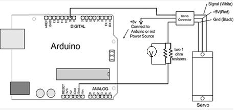
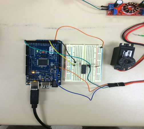
The following setup was used for this test:

Blog7_image2


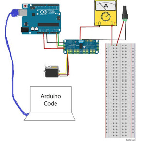
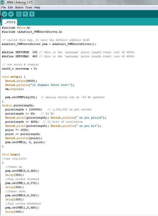
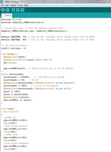
The test was run using breakout boards since they will be used to power the many servo motors in the final construction of Spiderbot. A plastic indicator was attached to the wheel of the servo, which was placed in front of a protractor since the test code used was based off of PWM adjustment as opposed to angle. The following image shows the test code that was used. Matthew Clegg modified the code that was provided by Adafruit (the brand of the breakout board used) to cater to this test:

Blog7_image3


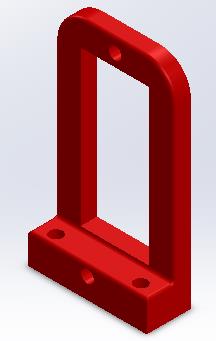
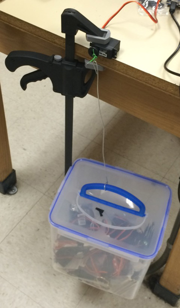
The final construction of Spiderbot will involve the use of metal brackets to securely connect the servos with the designed components, so a metal bracket was also used in this test. In order to acquire accurate current readings and properly mimic the motion that Spiderbot’s legs will use, small weights were attached to the end of the bracket.

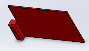
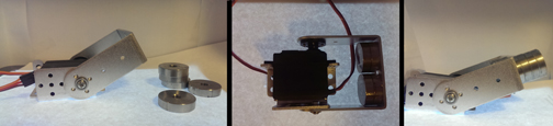
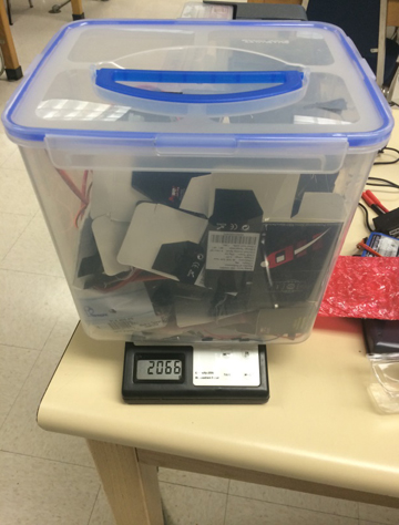
The estimated weight that a single leg servo on Spiderbot will have to support came out to be 437.55 g. This value was acquired using estimates provided by SolidWorks for the designed components and actual weight measurements from a scale for components that we had. The total is comprised of a single femur and tibia component, as well as three servos to account for a single leg, and 1/6 of the chassis design with all of the components it will hold (i.e. Android phone, pan and tilt platform). The total mass that was tested went up to as high as 500 g in order to account for the possibility of undershooting the final mass, keeping in mind the total mass that the servo can handle with the extended arm attached. The following image provides an idea of the approach taken in finding the current for varying lengths of the servo arm:

Blog7_image4


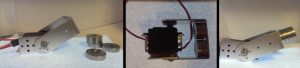
The first panel of the image shows the metal bracket and the small weights that were attached to it. In order to maintain a constant test mass with a varying arm length, the weights were first placed on the inner and outer portions of the bracket without exceeding the initial length of the arm, as depicted in the second panel of the image. Finally, the masses were stacked on the bracket to extend the length of the arm, as shown in third panel, and more current measurements were obtained.

 The current read through the multimeter varied constantly throughout the test, so the values that were recorded were the largest values that appeared consistently on the multimeter for each angle value. A quick video depicting the setup of this servo test can be found in the link below:

http://youtu.be/b5Dv5LfQsCQ

Discussion and Results

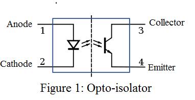
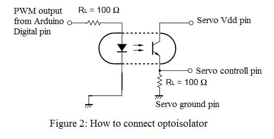
When working with servos, there are two currents worth noting: the idle current and the stall current. The idle current is the current consumed by the servo when it is not performing but connected to the power source. It is important to identify the idle current because it will provide users with the upper bound on how long a battery powered application can run. The stall current is the maximum current drawn by the servo when it is performing. The stall current will provide users with the minimum current requirement for the power supply. The actual current a servo consumes during operation will vary between the idle current and stall current. Servo currents usually are not specified by the manufacturer and the user is required to run tests to find the idle current and stall current. It’s easy to measure the idle current since it is low, constant, and only requires a simple connection to a power supply. A standard servo such as the Power HD High Torque Servo 1501 MG will have an idle current around 0.01 -0.03 amps depending on the power supply. Stall currents are more difficult to measure because stalling a servo can result in a damaged servo. A standard servo such as the Power HD High Torque Servo 1501 MG will have a stall current around 1 amp (finding the stall current of the Power HD High Torque Servo 1501 MG will not be attempted in this test.  Finding the current a servo draws during normal operation of the Spiderbot and Biped will be attempted instead). The current will be approximately linear with the supply voltage, so the currents drawn at 7 V will be almost double those at 4 V. Adjusting the rotational degrees of the servo will typically draw more current linearly. Increasing the torque by ten times will typically draw ten times the current.

Part A
IDLE CURRENT

Idle Current at 6.0 V = 0.03 amps

Part B
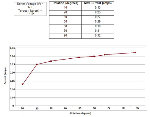
SHAFT ROTATION VS CURRENT

 Blog7_image5

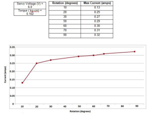
The graph shows how the current draw is affected by the increasing rotation of the servo’s shaft from 10 to 90 degrees. The current drawn increases steadily by approximately 10 mA as the rotation degrees increase by increments of 10 degrees. 

Part C
TORQUE VS CURRENT


Blog7_image6


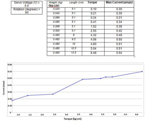
The graph shows how the current draw is affected by the increasing torque from 0.10 to 6.48 kg•cm. The current drawn increases by approximately 40 mA as the torque increase by increments of 1 (kg•cm). 

Current Draw

Figure 1: Circuit (Voltage showed on voltage meter will be equivalent to current draw from the servo) 

By Tien Dang

Objective:
For the Hexapod project, one of requirement is to determine the maximum current and to make sure the battery provide enough power for 18 servos to be run simultaneously and safely.

Servo Current:
In order to determine the maximum current, a trade off study has been done on the Power HD 1501 MG servo. We found out that the current drawn may reach up to 2.3 A.

http://www.pololu.com/file/0J729/HD-1501MG.pdf

To make sure the test is accurate; we performed a current test for our project to determine that the current will not exceed 2.3A. The maximum weight of the Hexapod (2066.74 grams which equal to 4.55 pounds), we used objects that has equivalent weight tie to the servo as following pictures.

figure 2

Figure 2:  Two parallel resistors were used to measure the current output following (figure 1 schematic).

Demonstration video for current testing:
https://www.youtube.com/watch?v=NhzRON_y3eg&feature=youtu.be

figure 3

Figure 3: Servo Strength Test

figure 4

Figure 4 : Object weight (2066 grams = 4.55 lbs)

After the test, we established that the maximum current with the 4.55 pound load is 450mAh at 6V.

Battery Choice:
Since there will be 18 servos that going to be used for the Hexapod,  the Turnigy 5000 mAh 2S 30C LiPo pack battery will be the sufficient choice in term of value and weight. Although the Venom battery might be a better choice because it can provide a much longer lifespan for the hexapod to operate (around 1 hour of operation) but due to its pricing ($50 plus shipping) and weight (288 grams which is 0.645 pounds) compare to the Turnigy battery ($20 plus shipping) and weight (275 grams which is 0.606 pounds).

http://www.hobbyking.com/hobbyking/store/__16202__Turnigy_5000mAh_2S_30C_Lipo_Pack_USA_Warehouse_.html

The Turnigy battery can deliver a high discharge rate, which equals to 300A. At the worst case scenario, the maximum current that needed for 18 servos is 81A. So this battery is a perfect choice to supply power for the Hexapod with a minimum duration of 7.5 minutes.

Formula to calculate discharge rate and duration:

Discharge rate = Battery Capacitor * Battery Capacitor Rating

Discharge Duration = (Battery Capacitor / Total Current Drain)

Conclusion:
After doing calculations, the Turnigy 5000mAH 2S 30C LiPo pack is a good choice to supply power for 18 servos with duration more than 7.5 minutes. The only problem that we encountered is the safety requirement. Due to the battery high delivering rate of current and power, we need to use opto-isolators and voltage regulator to protect the servos as well as the ADK board.

Mission Objective

By Mason Nguyen, Project Manager
and Elaine Doan

A hexapod is a six legged robotic capable of moving in all six degrees of freedom forward/backward, left/right, up/down with the combination of pitch, roll, and yaw rotations.  The objective is to deliver a hexapod that will need to operate safely during class room demonstration, capable of matching the speed with the rover, must be able to travel in a forest like setting while maneuvering over obstacles and must be built within $500 budget.

Requirements

  1. Hexapod will match the speed of the rover traveling on a surface with the speed of 0.20027 m/s or 7.8 inches/s as defined by the Rover Team.
    1. To match the speed of the rover, a calculation and verification testing will be performed so that Hexapod will have a walking speed of 8 inches in 1 second. 
    2. The hexapod will operate safely while navigating in a class room environment by operating a LiPo battery protection circuit in order to prevent the batteries from falling below or exceeding above the safe functioning point and avoid drawing too much current from the battery.
      1. Use power supply to mimic the battery and test and verify the performance of the protection circuit.
      2. The hexapod movement will be wirelessly controlled by the Arxterra Control panel via the Android Phone Arxterra app. Also it will utilize the phone camera to obverse the environment.
        1. Verification testing will be performed base on the Arxterra control panel test plan.
        2. The hexapod will travel and maneuver over obstacles 2.5 inches high at the designated terrain showed in figure (1 and 2).
          1. Angular swing of leg servos including Femur and Tibia servo will be calculated, and an2.5 inch object will be created in the classroom environment to test and to verify the maneuverable ability of the Hexapod.
          2. The project is anticipated to be within $500 range. However to improve the hexapod, the project budget could increase from extra components the team planning to add.
          3. The hexapod is expected to fully assembled by May 1st,2014. If time permits, the team will be adding more modifications. Demonstration will be presented by May 14h, 2014.

 figure 1

Figure 1. Location of the hexapod and spider bot Testing Terrain

figure 2

Figure 2. Route of the hexapod and spider bot going to travel.        


Height Requirement

By Maxwell Nguyen

Along the designated course shared by the Rover, Spiderbot, and Hexapod, the most notable obstacle was a sprinkler head with the height of four inches.  The orginal Arxterra RoSco is design to travel primarily through flat surfaces and is not equipped to move over obstacles at such height.  In order to clear this four-inch sprinkler, the rover team will be examining a design solution that will allow the new rover to achieve the height requirement.

The rover team has agreed that extending the height of the rover is the most simple and efficient design solution in order to fulfill the height requirement.  By taking the original chassis (or body) of the rover and extending both sides we will be able to give the rover a height clearance of 4 inches.

body

In order to extend the sides, several methods will be weighed against each other.  One approach will be to have the manufacturing division remodel the chassis of the rover to fit our needs.  However, due to time constraints and inefficiency from remodeling the chassis we will opt for a difference solution.

The most efficient solution the rover team decided upon is to mount two wooden height extensions, one to each side of the rover.  This will eliminate the need for plastic remodeling and simplify our design solution.  Similar holes drilled into the bottom of the wooden extensions will allow us to mount the motors, wheels, and track at the bottom of the extensions.  This will thus give the rover a significant height increase.

Opto-isolator

 By Chau To

Optoisolator is a component that transfers the signal between 2 isolated circuits. It consists of an LED and a phototransistor as shown in (Figure 1). When a signal is applied at anode (cathode is usually connected to ground), the LED will emit light that shines on the base of the phototransistor turning the transistor on. The optoisolator is used to isolate two parts of a circuit that has different power consumption such as between a micro controller and the DC motor.

Why Optoisolator?

Since the hexapod drives servos directly from the digital pins of the Arduino board, the Optoisolator will provide protection for the board by isolating the servo and Arduino. Since the servo consumes a large amount of current than the board, a power surge could happen and as a result the current from the servo could damage the Arduino. In addition, servo is a very noisy component; the noise could leak to the sensitive microprocessor.

How to connect?

figure 2

As demonstrated from the figure, the output from the PWM digital I/O pins of the Arduino connects the anode than the cathode is connected to ground. The Servo has 3 pins (or 3 wires). The Vdd wire connects to collector of the phototransistor; the other 2 wires connect like figure 2.

Operation: When the PWM is high, the LED lights up; the transistor will switch on. The servo control pin is high, and the servo shaft will rotate.

How to choose an optoisolator?

There are many types of optoisolator in the market. The two important parameters while choosing an optoisolator are the diode forward current and the switching time. The maximum forward current can be found in the data sheet; for the Ardunio the maximum rating forward current should be around 50 to 80mA. The switching time of the optoisolator determines how fast the phototransistor turn on, or what the delay is when the signal passes through the isolator. Nowadays, optoisolator has very fast switching time in micro-seconds.

The hexapod team will use a PS2501-4 Optoisolator 4-channel (4 Optoisolator in 1 IC) to operate the robot.

 Datasheet can be found at: https://www.sparkfun.com/products/784.

figure 3


Construction Update 2.0

By Mustafa Alkhulaitit – Project Manager

Up to this point, our team has been working on two main features of the 3D printer: the frame and the heat bed. After receiving the frame, our team has started assembling it and getting it ready to transfer the electronics to the new frame. The frame needed multiple parts to be printed that were printed with the help of Michael Pluma.  

The frame of the printer, both the old one and the new one, use rods for smooth movements of stepper motors. In order to transfer those rods to the new frame, the rods were sanded, cleaned, and cut for better appearance and better fit. So far, the frame is almost 90% done and just need some minor changes until it is finally ready.

 Fig.1

Fig.1: Pieces of the frame before assembly.

Fig.2 

Fig.2: The frame at about 90% completion.

The heat bed, on the other hand, is going to be the same, but will include a minor change. The aluminum plate, which forms the surface of the heat bed, was cleaned and sanded for better appearance. The base of the heat bed, or the heart of the heat bed, will have a newer look. We found the insulator material used, few pieces of cloth, is giving the base an unwanted thickness as well as an unattractive look. Therefore, the cloth will be removed and replaced by polyisocyanurate rigid foam insulated sheathing.

Fig.3 

Fig.3: The surface plate before cleaning and sanding.

Fig.4

Fig.4: The plate after sanding and cleaning. It now has a much better, smooth look and surface.

With the previous frame, the heat bed had four screw holes on the sides as can be seen in figure 5. The heat bed cannot be implemented with the same screws; therefore, the heat bed must be given new screw positions. 

Track Research

By Maxwell Nguyen, Project Manager

 The rover team is researching new ideas for treads/tracks for the rover.  The current tread belt is one continuous belt that takes hours to print.  In addition, one small mistake could potential ruin the entire track and make it completely useless.  In order to fix this problem, we will be looking into a new design that allows the belt to be split up into separate pieces.

Upon further research, we concluded that it was best to create our tread belt to resemble tank treads.  Tank treads are effective and can be produced as individual pieces before linking them into one continuous belt.  This will allow for faster track production and reduce the margin for error on the manufacturing end.

When searching for tank track models on Thingiverse (an open source community for 3D models and printing), we narrowed down three different types of tracks.  They can be viewed in the links below:

http://www.thingiverse.com/thing:163489

http://www.thingiverse.com/thing:163486

http://www.thingiverse.com/thing:199713

We will be working closely with the manufacturing division to develop a set a tracks and a new wheel to fit that will meet our rover’s needs.

Sasha’s Under Construction

By Mustafa Alkhulaitit, Project Manager

While waiting for the frame to be cut and ready for installation, our group has taken a step to save time and minimize any delay due to certain circumstances. The first upgrade that the advanced 3D printer team started working on was the LCD controller. We thought this upgrade was going to be the easiest; unfortunately, it took quite a while to get the LCD controller to work. There were multiple issues that we had to fix before the LCD controller got to work. The issues were mainly regarding the firmware and software updates/installation. Details regarding the issues we encountered will follow in a separate blog. Also, the solutions to those issues will be available along with the way our 3D modeler used in order to fix them.

Fig1 

Fig.1: The LCD controller before it worked.

 The LCD controller, as mentioned on a previous blog, offers some nice features such as controlling the axis, temperatures, and the heated bed. Almost every aspect of the 3D printer can now be controlled via the LCD controller. The g-code can also be uploaded on a SD card to free print without using a PC. This means we’ll have to consider the possibility of error prints and find away to stop the printer remotely.

 Fig2

 Fig..2

 Fig3

Fig.3

Figures 2 and 3 show the LCD controller after it worked.