
Written by Nornubari Kanabolo MST DM and Muhannad Al Mohamed E&C DM
Table of Contents
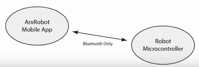
Training for telerobotic mode included understanding how “Community Mode”works. This can seen by the diagram below
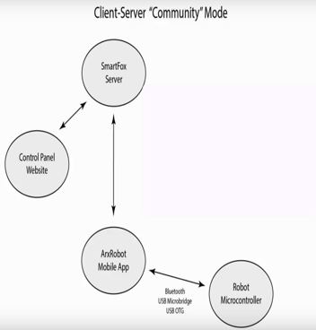
Community mode is communication between several parts of the Arxterra environment. This includes between the ArxRobot mobile app and Arxterra Control panel through a server and between the ArxRobot mobile app and ATmega32U4 microcontroller.
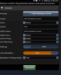
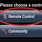
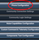
1. Click on Community Mode in the ArxRobot App. This is

2. Do not change any of these default settings
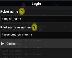
In order to create a name for the project, type in your robot name as seen below. For example, for the Goliath project, you would put “Goliath” in the “Robot name” area. For “Pilot name or names” you would put your individual birth name such as “Nornu”.
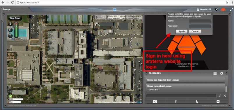
To access the Arxterra Control Panel, go to arxterra.com and click on “Launch Now!” in the control icon.
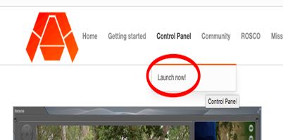
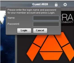
Now you log in to the control panel using your Arxterra username(assuming you already registered for an account) and password for Arxterra.
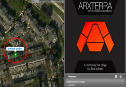
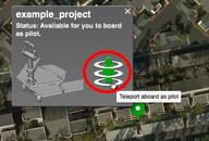
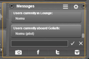
Once in community mode and logged into the control panel you should be able to see your robot on the map. It is signified as a colored location marker. Click this and it will show the name of the robot and a “beam me up, Scottie!” icon. Click this icon to switch to Pilot mode.
 →
→ 
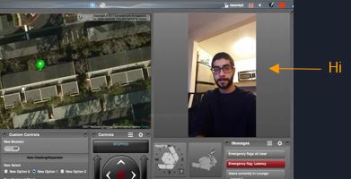
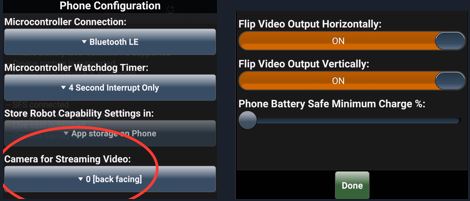
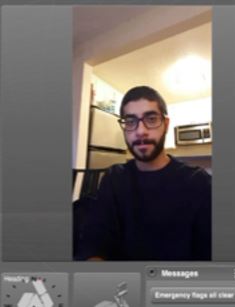
Now you should be able to see what your phone camera sees. The interface created through the ArxRobot mobile app should be visible now as can be see below. To change the view of the camera through the app go to the settings>>phone configuration>>camera for streaming video.
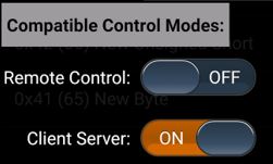
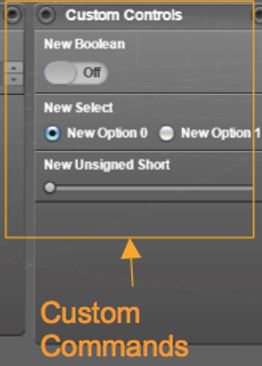
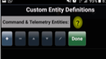
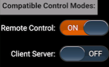
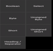
The process of creating Custom Commands & Telemetry in Community Mode is exactly similar to the process in creating them in RC Mode. It has the same 7 options the users can choose from (Boolean, Select, Byte, Unsigned Byte, Short, Unsigned Short, Header/Separator). However, Instead of only enabling the commands to show up in RC Mode the user would enable it to show on the Client Server Mode.
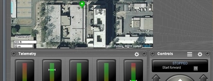
The user interface has 7 windows to show data:

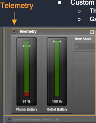
Telemetry is an automated communications process by which measurements and other data are collected at remote or inaccessible points and transmitted to receiving equipment for monitoring data.
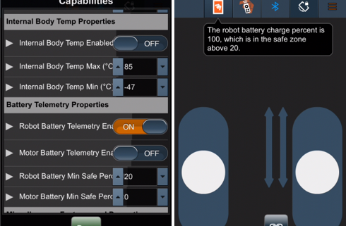
The data packets sent from the 3DoT to the ArxRobot App can be displayed in the telemetry window by enabeling either Telemetry State or Telemetry Stream for custom Commands.
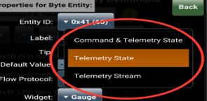
Predefined telemetry can also be shown in the window if enable in the Robot Capabilities Configuration.
Written By: Muhannad Al Mohamed (E&C DM)
Table of Contents
The Arxterra 3DoT App training had a goal of teaching E&C and MST members how to use their phones to communicate with their projects through Remote Control Mode. The ArxRobot Application has two different modes of communication with the Robot’s Microcontroller. The Remote Control Mode (covered in this training) and the Community mode (Covered in the next training session). The user, through the ArxRobot App, should be able to send commands to the microcontroller either through predefined commands or custom made ones.
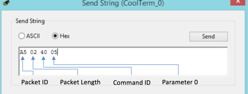
The communication in the RC mode is done wirelessly through Bluetooth with an easy pairing process at the initialization of the RC mode. Commands are sent to the microcontroller as packets that consist of bytes that have specific identifiers to indicates whether the command is a command or telemetry. The packets contain data bytes that can be processed by the pre-coded microcontroller.
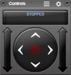
The user interface in the RC mode is user-friendly. The default setting shows the controls of two motors in a strip type command. The strip can be changed to a D-pad looking control. Custom commands can be set to show on the user’s interface when enabled.
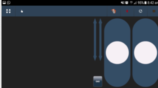
During the training session, members were taught how to use the user interface to control motors by giving specific input, moving motors at the same time, and steering trim to maintain desired speeds.
The commands used in the app can be changed in the settings of the app. To access the predefined and custom commands users needed to be in Developer Mode.
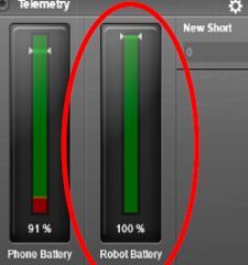
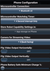
The Phone Configuration window in the setting enables the user to choose the way to connect to 3DoT board, show phone’s battery percentage on Control Panel, and flip Camera’s position.
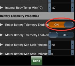
The predefined commands are commands and telemetry functions defined by the Robot3DoTBoard and saved in the app as default commands to operate a Mar’s Rover. These commands, if needed, can be used by the user by enabling each command in the Robot Capabilities configuration.
The Custom Command & Telemetry Configuration window allows the user to create new commands to be sent the 3DoT Board and receive Telemetry from it.
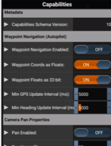
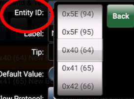
Options for commands and telemetry is created by adding an option and giving it a specific address from (0x40) to (0x5F). Each option should be chosen to be either for commands to be sent to the 3DoT or Telemetry to be sent by the 3DoT. Commands can be controlled by the ArxRobot App; however, not all telemetry options are shown on the app. Each option should be enabled to show in either RC mode or Community Mode.
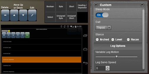
There are 7 options the user can choose while creating a custom command:
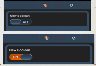
1- Boolean:
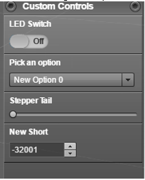
This option enables the user to send a byte in the data packet to the 3DoT board with a value of either (0x00) or (0x01). In the user’s interface, it can be seen as a switch that can be changed. The user can choose a default value of either of the previous options. This option can be used to turn an LED on and off for example.
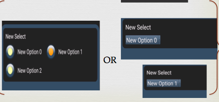
2- Select:
This option enables the user to have multiple outputs to switch to. It is similar to the Boolean switch; however, it can have as many options the user wants to switch into. It sends a 1 byte of data parameter with the packet that is sent to 3DoT board; however, the values sent can be modified by the user. The select option shows in the user’s interface as radio buttons.
3- Byte:
This option can be used to send a byte in the data packet but with a wide range that can be changed by the user. It has a default range from -127 to 128 where the user can control which value sent by moving a strip in the user’s interface. These values can be changed by the user in the Byte settings to the desired range but it would still be a byte range. The steps between each value can be modified as well. This option can be used to move a servo motor for example.

4- Unsigned Byte:
This option is similar to the Byte command. The only difference would be the default range that starts from 0 up to 255.
5- Short:
This option is also similar to the Byte/Unsigned Byte; however, this option sends two bytes in data packet. Because it sends two bytes, the short command has a wider range than Byte/Unsigned Byte. The default value of this options ranges from -32768 to 32767.
6- Unsigned Byte:
This option is similar to the short option; however, the default range for it goes from 0 to 65535.
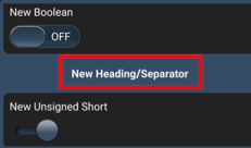
7- Header/Separator:
This option does not send any data in packets sent to the 3DoT; however, it is used to make the interface more user-friendly. titles to commands can be given using this option and it can be used to as separator if it was used without writing anything to it.
Arxterra RC Mode training document can found at this link.
Update: 12/5/2017
By creating custom commands and telemetry, engineers can create commands that can enable them to control their projects through the maze. For example, the path taken by a robot can be sent back to the phone connected to the MCU using telemetry options to show which room the robot is in on the phone’s display using RC mode. By optimizing the translated code from EE346/EE444 written by Mark Huffman (Goliath Project Manager) and Matt Shellhammer (ModWheels E&C Engineer), the variable “room” value can be sent as telemetry to the ArxRobot app. In the ArxRobot app, a telemetry Select command should be created and called room where it shows the byte value on the phone.
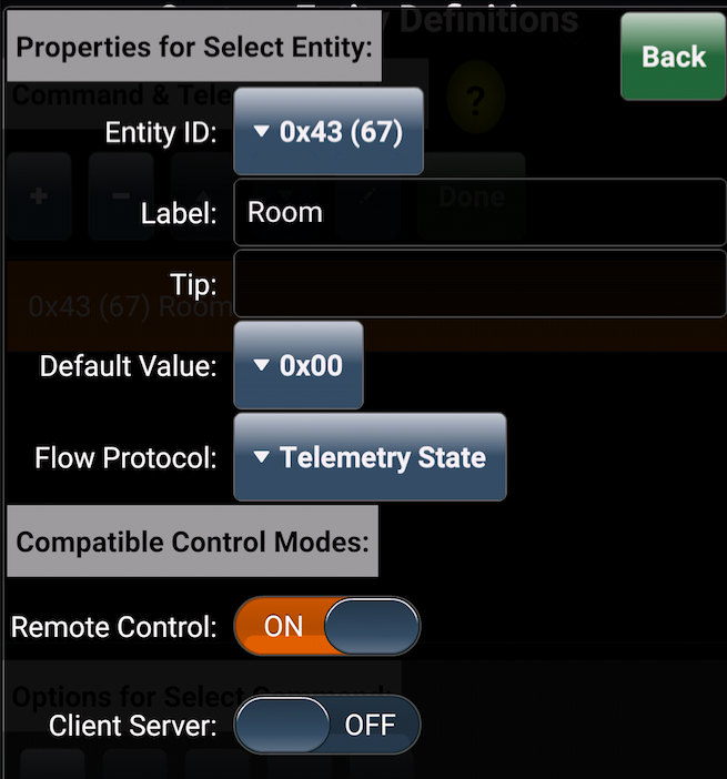
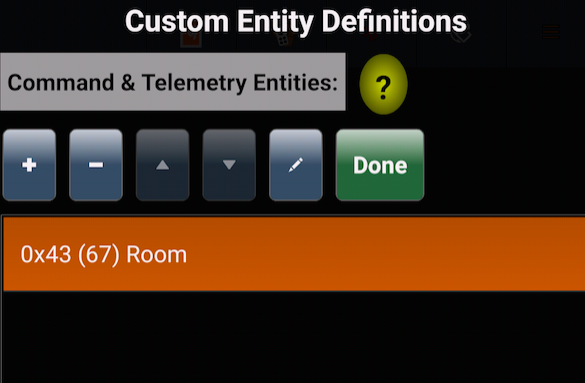
Creating Telemetry command called Room
Selec command Room
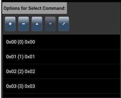
Assigned options to show the room type as implemented from the maze
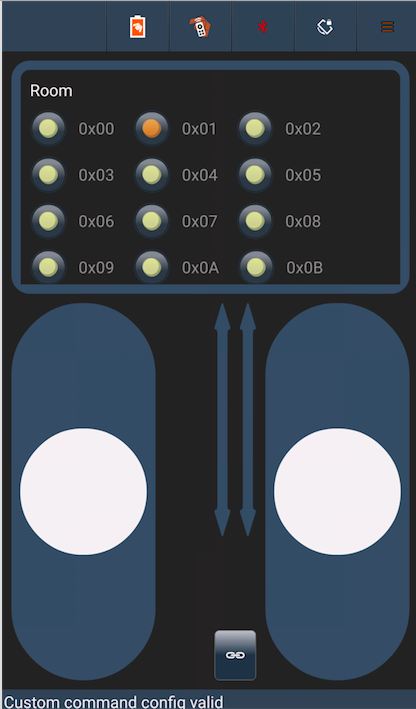
Room type is shown in RC mode interface
The same process can be implemented to apply choosing the phase each robot is taking. In her blog Mission Definition, Elizabeth Nguyen (Pete-Bot Project Manager) explained how there are four planned phases each project can take:
This custom command can be applied by also creating a select command with the four options where the user can switch easily between phases.
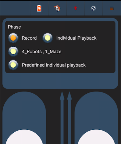
Phase selection in RC Mode
Whenever Phase 1: Record is selected, the robot should start saving its path in the EEPROM. The EEPROM library can be very useful to record data when the system shuts down, which is essential in keeping data. The process of saving the path the robot is taking is explained in Write to EEPROM blog written by Matt Shellhammer (ModWheels E&C Engineer).
By Tommy Sanchez
This guide will help you start communicating between your robot and an android phone. The topics covered are: how to connect your phone to the Arduino, the communication from phone to Arduino for commands for your robot, and communication from the Arduino to the phone for telemetry. Make sure to view the Getting Up and Running tutorial, along with the one on Custom Commands beforehand. A link to the Arduino Code for communication is also found in this guide.
An important thing to note is that there are two ways of physically connecting your phone to the Arduino, which is explained on the guide. In efforts to check communication compatibility on your phone, please be sure to have both applications discussed on the Getting Up and Running tutorial installed on your phone. This will allow you to try both connection types if one of them doesn’t work for you.
Click on the link below to download the PowerPoint communications tutorial:
By Tommy Sanchez
If you have read the previous tutorial on getting up and running with the control panel and applications, then you’re ready to learn how to create custom commands through the Arxterra application. These custom commands will allow you to expand the capabilities of your robot. In outline form this tutorial covers: creating a custom command, the command control panel interface, and implementation examples.
Types of command options:
Each of these are covered in depth. Command types must have their own unique identifier called a Command ID. This ID can be chosen from a range of 0x40(64) to 0x5F(95). Command types also have 1 or 2 value bytes associated with the command. These bytes are used by the microcontroller to identify what instruction it’s receiving.
While you are walked through adding a command type you will also be able to see each command type’s interface on the control panel. To take it a step further once you know how to add a command and know how it appears on the control panel, you will be shown implementation examples for robots such as a Biped, Hexapod, and Rover. As a quick example, Boolean can be used as an On/Off switch for the legs of a Biped robot. How the data is sent over to the microcontroller in the form of a byte array is also covered. The provided link below will take you to an easy to follow PowerPoint tutorial outlining these topics. Enjoy.
PowerPoint Tutorial:
http://www.csulb.edu/~hill/ee400d/Lectures/13_Arxterra%20Commands.pptx
By Tommy Sanchez
If you are interested in controlling your robot with the Arxterra control panel, you have come to the right place. For your robot to be controlled through the control panel, you will need to have an Android phone for communication with your Arduino. This guide will show you how to create an account with Arxterra, get access to the alpha testing for the Arxterra applications, connect on the applications, and log in to the control panel. The provided link below will take you to an easy to follow step-by-step PowerPoint tutorial outlining these topics.
PowerPoint Tutorial:
http://www.csulb.edu/~hill/