Table of Contents
The System Engineering Method
Mission Authority > Start
- Customer[1] Expectations (Project Objectives and Mission Profile)
- High Level Requirements (Level 1 Program/Project)
- Functional and Logical decompositions (Project WBS)[2]
- Trade Studies and Iterative Design Loop
- Form Creative Design Solution (System PBS)
- Define Level 2 System and Subsystem Requirements
- Make Hardware and/or Software Model(s) and Perform Experiments
- Organize and Analyze Data
- Does Functional & Performance Analysis show design will meet Functional Design and concept of operations (ConOps) Requirements?
- If additional detail need, Repeat Process
- Select a preferred design
- Does the system work[3] (performance)?
- Is the system achievable within cost and schedule constraints?
- If the answer is no, adjust Customer’s Expectations (Step 1) and start again.
- Communicate Results (PDR and CDR)
- Preparing presentations (PDR and CDR)
- Reports, plans, and specifications. (Project Planning)
- Implement the design. (Project Implementation)
What is the difference between Level 1 and Level 2 Requirements?
For EE400D we have consolidate the typical 5 requirement levels: Program, Project, System (included Allocated), Subsystem, and Design, into only two: Program/Project and System/Subsystem. For this course therefore you can differentiate between the two levels by asking yourself the following question. Does the requirement imply a solution, if it does it is at level 2, otherwise it is level 1. One exception is if the customer specifies a design solution as part of their project expectations, in which case it is a level 1 requirement.
Requirement Flowdown
High-level requirements are decomposed into functional and performance requirements and allocated across the system. These are then further decomposed and allocated among the elements and subsystems. This decomposition and allocation process continues until a complete set of design-to requirements is achieved. At each level of decomposition (system, subsystem, component, etc.), the total set of derived requirements must be validated against the stakeholder expectations or higher level parent requirements before proceeding to the next level of decomposition.
The traceability of requirements to the lowest level ensures that each requirement is necessary to meet the stakeholder expectations. Requirements that are not allocated to lower levels or are not implemented at a lower level result in a design that does not meet objectives and is, therefore, not valid (under-design). Conversely, lower level requirements that are not traceable to higher level requirements result in an over-design that is not justified. This hierarchical flow down is illustrated in Figure 1.0.
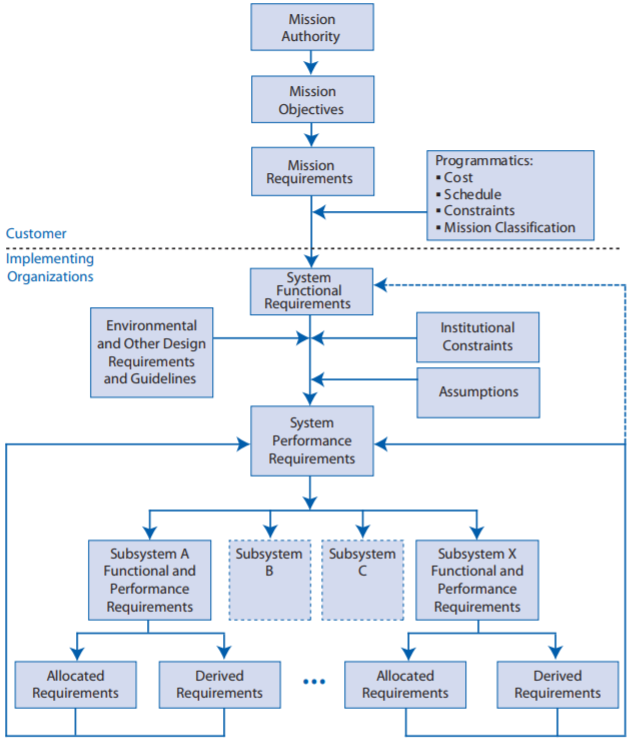
Figure 1.0 The flowdown of requirements
As illustrated in Figure 1.0 constraints may come from the customer “Programmatic” or the implementing organization “institutional.”
How to Find Level 2 Requirements
When writing level 2 requirements start with the Harware System Block Diagram[1] and Software Block Diagram. Then come up with requirements needed to design each block. By definition, these are level 2 and are needed to build the system.
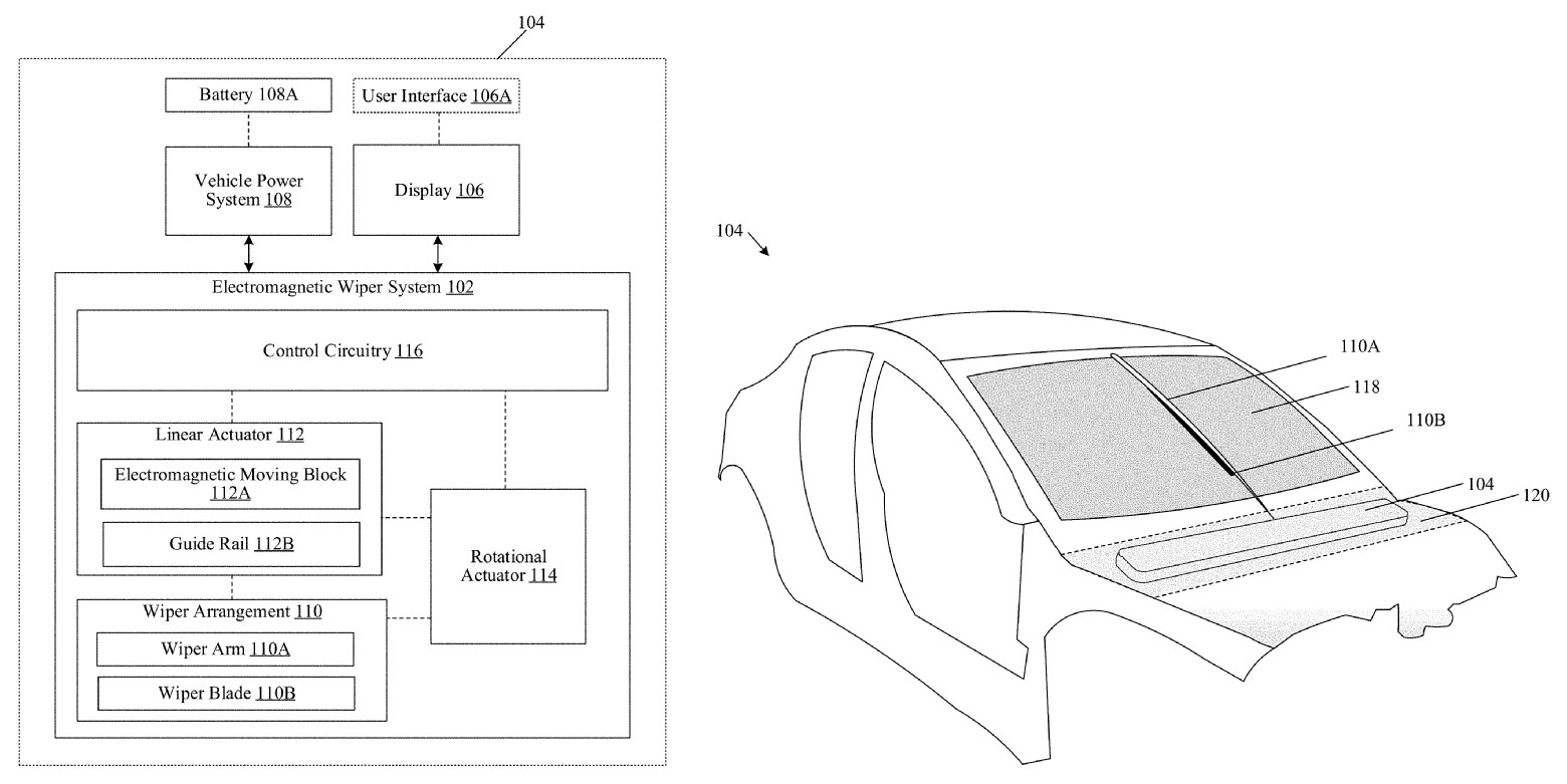
Figure 1. Tesla’s electromagnetic windshield wiper system. (Credit: US Patent Office)
Level 2 Requirement Examples
In the “Requirements and Dunker Diagram” lecture, examples of Level 1 Program/Project by Tesla and Pathfinder were highlighted. In the following example we will take a look at Level 2 System/Subsystem Requirements.
Hexapod (L2 Subsystem Requirements)
- The Hexapod Project Document is named Executive Summary Project – November 1, 2013. The Executive Document provides a short summary paragraph and then links to all critical documentation within the blog. This is a nicely written document, and provides a good case study on derived requirements (flow down) and allocated requirements.
Battery
- The Hexapod requirements are located in 3 documents. Let’s focus on selecting specifications for the battery, which is a function of…
- Mission duration (Time = Distance/Speed)
- Average current
- Maximum current
- A number of ancillary factors including, power supply efficiency and depth of discharge also come into play.
Hexapod Mission Duration (Distance / Speed)
Mission Duration is derived from knowing the robot’s actual speed and course layout.
“The Hexapod will be able to match the speed of the rover currently being designed by the 400D Rover team…The speed of the rover will be defined at a later time.” – Project Requirements, October 29, 2013
“To match the speed of the rover, a calculation and verification testing will be performed so that Hexapod will have a walking speed of 8 inches in 1 second.” – Mission Objective, April 22, 2014
- Distance Quiescent
“The Hexapod will be designed to operate safely during a demonstration in class and a complete running of the course laid out for the Hexapod at the traffic terrain (see Figure 1).” – Project Requirements, October 29, 2013
“Figure 2. Route of the hexapod and spider bot going to travel.”
– Mission Objective, April 22, 2014
- Mission Duration
- Ultimately, the mission duration was not specified in the October 29, 2013 System Requirements, or the April 22, 2014 Mission Objective documents. It does appear in the April 23, 2014 Current Draw blog post, listed as 5 minutes. This was the last Hexapod blog post.
Hexapod Average Current
Current is an allocated requirement, which includes a current breakdown by component. How could the TBDs have been filled in? Without knowing mission duration and current requirements, battery sizing becomes problematic – Resource Report October 31, 2013.
“The Hexapod will have power supplied from a portable source, such as a battery, so that it can be controlled remotely and without any other equipment.” – System Requirements, October 29, 2013
- Is this an L2 system requirement? As with most robots a power budget is critical and the responsibility of the system engineer.
Hexapod Battery Specification
“The battery chosen for the build will need to provide power for 18 servos and the control board. It will need to be rechargeable and be within budget. The weight of the battery must not excess 1/5 the weight of the full Hexapod. The battery must have better run time to provide full electricity for at least 20 minute operation. It must also provide enough current for all servos. The suitable range of current is from 2700mA to 3600mA (150mAh to 200mAh per servo). The battery should have a high discharge rate order to deliver the large amount of power at once. For safety requirement, the maximum safe continuous discharge rate must be greater than the maximum current drawn from the servos and electronics boards”
Battery Choices – November 1, 2013
- With textual content missing the battery study does not draw any conclusions from the tests and leaves the reader wondering why the tests were even conducted.
- Notice mission duration of 20 minutes has been selected. How was this time derived?
Hexapod versus UFO Abducted Battery Specification
Compare the Battery specification of Hexapod versus battery specification for UFO Abducted.
Hexapod Servo Specification
Are these requirements? To see how it turned out check out their fun video:
A Note on Standards
Standards provide technical requirements across a program to avoid incompatibilities, lower cost, establish materials and process specifications, test methods, and interface specifications, to name a few. Standards are applied across the projects life-cycle, including design, fabrication, verification, validation, acceptance, operations, and maintenance.
Standards are generated from many sources, leading to confusion, contradiction, and a need for prioritization. Here is one way standards may be prioritized.
- Standards mandated by law (e.g., environmental standards)
- National or international voluntary consensus standards recognized by industry,
- Government standards
- Customer and Institutional policy directives, and technical standards.
As an example, the selection of a computer-aided design CAD package may depend on on its ability to meet specific standards, such as model accuracy, dimensioning and tolerancing, the ability to create different geometries, and the capability to produce annotations describing how to build and inspect the part.
[This section is an abridged version of the NASA System Engineering Handbook, Sections 4.2.2.5 Technical Standards and 7.3.4 Design Standards.]