DeRobot Generation 1 Summary Blog Post
Author/s: Alexander Littleton (Game Software/Controls), Jorge Mendoza (Navigation), Matthew Ibarra (Card Reader), Thomas Bender (Boost)
Verification:
Approval:
Table of Contents
Executive Summary
Program and Project Objectives
Program Objectives
Your team has been tasked with designing a self-balancing robot that will be participating in a competition to map an unexplored maze/cavern/ruin and then retrieve all of the valuables and weapons in the shortest time possible. There will be monsters blocking certain paths and they can be eliminated with certain equipment that can be picked up within the maze. The expedition will be done on a unique maze/cavern/ruin that is generated by randomly placing markers (valuables, monsters, weapons), walls, and bridges on the printed maze. The robot will have a designated starting position that may or may not be at a maze entrance and it will need to return to that location with the valuables/loot. It is anticipated that teams will use the mapping phase to discover the location of the wall(s), bridge(s), and marker(s) within the maze, prior to the retrieval phase.
Project Objectives
The DeRobot project will effectively navigate through the maze at a quick pace by utilizing the 3DoT robot along with a boost system, external memory, and orientation sensor designed on top of the robot. The 3DoT board allows for a faster pace of development due to the offloading of mechanical design expertise in addition to the existing software infrastructure and support that the 3DoT community provides. The boost system allows the robot to temporarily go faster than a standard 3DoT robot could go, which would reduce the time it takes for the robot to traverse the maze. The external memory allows the usage of pathfinding algorithms that would not be capable of being run on the 3DoT board. The improved pathfinding algorithms would allow the robot to traverse a smaller amount of squares to navigate the maze, improving solving time.
Mission Profile
Link: http://web.csulb.edu/~hill/ee400d/Maze%20Project.pdf
In-Class Maze Competition
In the past students have started the class by defining a mission and a robot (the project) to complete that mission on the day of the final exam. This spring the mission was a game the robot competed in the Maze.
Both the game and project facilitate the teaching of the Engineering Method and the design and fabrication of an electrical circuit implemented using SMT devices fabricated on a small PCB, known as a shield. The focus of the semester is more on electrical engineering, with the robot and game as supporting actors.
For the senior design course, there are two primary goals for the student to experience. To work with other students in an environment that simulates what you will see in the industry (i.e., The Engineering Method). During the COVID pandemic, virtual forms of communication substituted face to face engagement.
To gain practical experience by building a real project. Group members built robots at home and supplied themselves with 3D printed parts from who owned the equipment or had accessto producing them. . Students sourced electrical equipment needed for soldering, due to the risks of COVID it would be unsafe for accessing lab facilities on campus. .
With the current situation, it could be unsafe (sending parts to other teammates) or relatively expensive (all members buy the parts needed). At the minimum, we are planning to have students design and fabricate a printed circuit board (PCB). Students will purchase a “Maze Kit” from Humans for Robots. By standardizing on this kit we solve most of the problems posed by the Pandemic.
- Class works on a common Mission Objective.
- Each class member has access to the project hardware.
- Each team gets real-world electrical engineering experience by building a small low-cost custom SMD PCB. Within the Arduino community this PCB is known as a “Shield.”.
Project Features

Figure 1: Software block diagram
The DeRobot project has 7 subsystems, 6 of which utilize externally connected hardware that are present on 2 connected modules as shown on the block diagram above. The first module is called the “top hat” and contains EERAM for storing maze information, an IMU for obtaining the robot’s orientation, and a boost converter to allow the robot to move faster. The second module is the “front hat” which contains the navigation color sensors in order to track the maze walls and the card reader color sensor to detect cards within the maze. The other two features of the robot that are not on either module are the control system and the game software module. The control system controls motors on a 3DoT board in order to let the navigation and game software move the robot. The game software takes in information from other subsystem and makes the robot go around the maze by sending commands to other subsystems
Requirements
Each subsystem of the DeRobot project was designed, built, and tested in accordance with the following engineering standards and constraints. Furthermore, Level 1 requirements reflect design choices based upon the rules of the game, making them specific to the MazeBot project. More specifically, the hardware implementation for each subsystem was chosen based on these Level 1 requirements. Since there are numerous hardware solutions to the multi-faceted MazeBot problem, these level 1 requirements are design-independent, meaning that they must be upheld no matter what the final hardware implementation. Moreover, Level 2 requirements reflect design choices contingent upon the hardware implementation chosen. In other words, the Level 2 requirements are strictly design-dependent.
Engineering Standards and Constraints
Applicable Engineering Standards
- IEEE 29148-2018 – ISO/IEC/IEEE Approved Draft International Standard – Systems and Software Engineering — Life Cycle Processes –Requirements Engineering.
- NASA/SP-2007-6105 Rev1 – Systems Engineering Handbook
- C++ standard (ISO/IEC 14882:1998)
- Arduino De facto Standard scripting language and/or using the GCC C++ programming language, which is implements the ISO C++ standard (ISO/IEC 14882:1998) published in 1998, and the 2011 and 2014 revisions
- Federal Communications Commission (FCC) Relevant standards for a product implementing digital logic between 9kHz and 3000GHz, FCC Intentional Radiators (Radio) Part 15C, and Unintentional Radiators FCC Part 15B for CPU, memories etc.
- NXP Semiconductor, UM10204, I2C-bus specification and user manual.
- ATmega16U4/ATmega32U4, 8-bit Microcontroller with 16/32K bytes of ISP Flash and USB Controller datasheet section datasheet, Section 18, USART.
- USB 2.0 Specification released on April 27, 2000, usb_20_20180904.zip
- American Wire Gauge (AWG) Standard
Environmental, Health, and Safety (EH&S) Standards
- IEEE National Electrical Safety Code (NESC)
- NCEES Fundamental Handbook (FE) Reference Handbook
- CSULB COE Lab Safety
ASTM F963-17, The Standard Consumer Safety Specification for Toy Safety, is a comprehensive standard addressing numerous hazards that have been identified with toys. In 2008, the Consumer Product Safety Improvement Act of 2008 (CPSIA) mandated that the voluntary toy safety standard in effect at that time become a nationwide mandatory children’s product safety rule.
Program Level 1 Requirements
L1.001: The robot shall participate in a competition as defined in the “Rules of the Game.”
This requirement will be verified upon completion of the game as defined in the “Rules of the Game.” A minimum level of compliance with this requirement is defined by verification of requirements L1.101 to L1.113. See the rulebook for how points are awarded. Some points are awarded based on the time required for your robot to complete/solve the game/maze.
L1.002: The robot should win the competition. The robot earning the most points at the end of the Zoom meeting wins. See the rulebook for how points are awarded. Some points may be awarded based on the time required for your robot to complete/solve the game/maze.
L1.003-4: The robot shall be discovering cards placed through the maze during the mapping phase as defined in the “Rules of the Game”
L1.004.1: The robot will be constructed using the PaperBot chassis as the foundation of the design.
L1.005: Each member will provide a custom SMD PCB design except for the Game Software Engineer
L1.006: During the mapping phase of the mission, the robot shall digitally encode the maze without human interaction. A predefined maze identifying hedges, entrances, and exits (available here) may be pre-encoded at the team’s discretion. After the mapping phase, the encoded maze shall include all features in the provided maze, plus cards, walls, and bridges.
L1.007: The robot shall discover cards placed throughout the maze during the mapping phase as defined in the “Rules of the Game”.
The success criteria is that the robot is able to identify and differentiate the three types of cards (treasures, monsters, weapons).
L1.008: The robot shall autonomously determine its coordinates and orientation (NORTH, EAST, WEST, SOUTH) in a maze, within a 10 minute period of time. This process is defined as “calibration.”
This requirement will be verified by the customer by placing the robot in a pre-encoded maze. This maze may be the standard maze (included with the kits), or the maze as it exists after a maze has been mapped and digitally encoded.
L1.009: The robot shall autonomously navigate the maze..
The robot traverses the path defined by the game software at the conclusion of the mapping and calibration.
L1.0010: The cards placed throughout the maze will be placed in the center of the placed room.
L1.0011: The robot shall record the changes to the maze from the placement of walls and bridges during the mapping phase.
L1.0012: The robot shall determine its position within the maze during the calibration phase
L1.0014: The black lines defining the boundaries of a room in the maze have a width of 8pts
L1.0015: A maze path has a minimum distance of 2.25” from edge-to-edge. With an 8pt line center-to-center, a maze square is 2.861”x2.861”
L1.015: The robot will be fully assembled by May 10th
L1.8: The robot shall autonomously navigate the maze during the execution phase
L1.9: The robot shall fully exit the maze once it has completed the mission
Project Level 1 Functional Requirements
L1.1: The robot shall be participating in a competition as defined in the “Rules of the Game”. The robot earning the most points wins. See the rulebook for how points are awarded. Some points are awarded based on the time required for your robot to complete/solve the game/maze.
L1.2: The robot will be constructed using the PaperBot chassis as the foundation of the design.
L1.3: Each member will provide a custom SMD PCB design except for the Game Software Engineer
L1.4: The robot shall be discovering cards placed through the maze during the mapping phase as defined in the “Rules of the Game”
L1.5: The cards placed throughout the maze will be placed in the center of the placed room.
L1.6: The robot shall record the changes to the maze from the placement of walls and bridges during the mapping phase.
L1.7: The robot shall determine its position within the maze during the calibration phase
L1.8: The robot shall autonomously navigate the maze during the execution phase
L1.9: The robot shall fully exit the maze once it has completed the mission
L1.10: The black lines defining the boundaries of a room in the maze have a width of 8pts
L1.11: A maze path has a minimum distance of 2.25” from edge-to-edge. With an 8pt line center-to-center, a maze square is 2.861”x2.861”
L1.12: The robot will be fully assembled by May 13th
System/Subsystem/Specifications Level 2 Requirements
Card Reader Requirements
L2.1: In order to fulfill requirements L1.1 and L1.4, the card reader system shall construct hardware and software required to detect and report any cards that are directly underneath the robot.
L2.2: In order to fulfill requirements L1.1, L1.4, and L1.5, the card reader system shall successfully detect a card within a square before the robot leaves that containing square.
L2.3: In order to fulfill requirement L1.1, the card reader system shall detect all cards with no false positives or false negatives within 1 run of the maze.
L3.1: In order to fulfill requirements L1.1, the navigation system shall construct hardware and software required to keep the rover aligned with the maze grid deviation not to exceed 1/2 of the robot’s width(<3cm). L3.2: In order to fulfill requirements L1.7 and L1.6, the navigation system shall provide the room wall configuration encoded in the format described by Hill’s encoded made document by the time that the robot has left the square.
L3.3: In order to fulfill requirements L1.9 and L1.8, the navigation system shall track the position and orientation of the rover throughout the maze.
Control System Requirements
L4.1: In order to fulfill requirements L6.1, L6.2, and L6.3 the control system shall construct hardware and software required to turn and move the robot in accordance with commands sent by the maze system.
L4.2: In order to fulfill requirements L3.1, the control system shall construct hardware and software required to turn the robot in accordance with commands sent by the navigation system.
L4.3: In order to fulfill requirements L3.3, the control system shall notify the navigation of when a turn is complete.
L4.4: In order to fulfill requirements L3.1, the control system shall turn corners accurately enough to let the navigation system maintain tracking to the maze (22 degrees).
Boost System Requirements
L5.1: In order to fulfill requirements L1.1, the boost system shall construct hardware and software required to speed up the robot by overvolting the motors.
Game System Requirements
L6.1: In order to fulfill requirements L1.4 and L1.6, the maze system shall construct hardware and software required to make the robot map and store the configuration of the maze.
L6.2: In order to fulfill requirements L1.7, the maze system shall construct hardware and software required to make the robot find the initial position of the robot during the calibration stage.
L6.3: In order to fulfill requirements L1.8 and L1.9, the maze system shall construct hardware and software required to make the robot collect all the cards efficiently and exit the maze when finished.
L6.4: In order to fulfill requirements L1.1, the maze system shall construct hardware and software required to ensure the robot does not break “The rules of the game”.
Allocated Requirements / System Resource Reports
L1.205: The mass of the robot will not exceed 300 grams.
Compliance will be provided in Section 3.4 Mass in the Final Blog Post. Measured mass shall have a margin of 2%. Contingency shall be based on measured mass, plus margins associated with each line item, minus 300 grams.
| System Name | Allocated Mass | Expected Mass | Measured Mass | Margin Mass |
| Front Hat | 50g | 5.38g | 6g | 0.12g |
| Top Hat | 50g | 5.44g | 6g | 0.12g |
| Supercapacitor | 100g | 38.15g | 37g | 0.74g |
| 3DoT | 100g | 100g | 94g | 1.88g |
| Totals | 300g | 148.97g | 143g | 2.86g |
| Contingency | 154.14g |
Table 1: Mass allocation table
L1.206: Power to the robots will be provided by the 3.7V Li-Ion battery included with the 3DoT board, with a capacity of 700 mAh (min) to 750 mAh (max) and a power rating of 2.59 (min) – 2.775Wh (max) (included with the 3DoT board). Use of an external battery will use a 2.0mm PH series JST connector located on the 3DoT board and covered in a separate requirement.
Compliance will be provided in Section 3.5 Power in the Final Blog Post. Measured current shall have a margin of 5%. Contingency shall be based on measured current, plus margins associated with each line item (e.g., datasheet), minus 750 mA with an assumed depth of discharge of 80% (i.e., 560mA min, 600 mA ).
| System Name | Allocated Current | Expected Current | Measured Current | Margin Current |
| Front Hat | 20mA | 20mA | 16.7mA | 0.835mA |
| Top Hat | 20mA | 2mA | 1.37mA | 0.0685mA |
| Supercapacitor | 690mA | 690mA | 710mA (peak) | 35.5mA |
| 3DoT | 20mA | 20mA | 19.6mA | 0.98mA |
| Totals | 750mA | 742mA | 747.7mA | 37.38mA |
| Contingency | 35.08mA |
Table 2: Power allocation table
Project Report
In this section, the project management portion of the DeRobot design will be described. This section will include the project’s work breakdown structure(WBS) and product breakdown structure(PBS). In addition, a cost breakdown of the robot will be provided with a schedule and a status report on the scheduling of the project.
Project WBS and PBS
Work Breakdown Structure
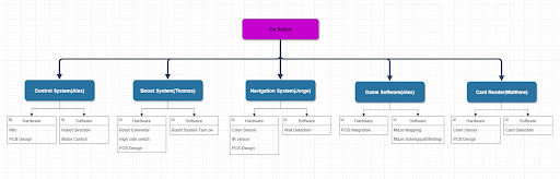
Figure 2: Work Breakdown Structure
Product Breakdown Structure
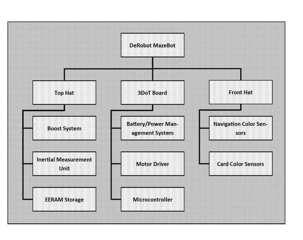
Figure 3: Product breakdown structure
Cost
| System Name | Allocated Cost | Expected Cost | Measured Cost | Margin Cost |
| 3DoT | $110 | $110 | $110 | $2.2 |
| Top Hat | $40 | $30.85 | Stencil:
$5.00 (per) PCB: $6.95 (per) Components: $18.90 (per |
$0.62 |
| Front Hat | $40 | $38.66 | Stencil:
$6.31 (per) PCB: $10.80 (per) Components: $21.55 (per) |
$0.77 |
| Boost Hardware | $20 | $16.49 | Capacitor:
$16.12 (per) Diode: $0.37 (per) |
$0.40 |
| Navigation Research | $10 | $10 | $42 | $0.84 |
| Control Research | $10 | $10 | $16.95 | $0.34 |
| Card Reader Research | $10 | $10 | $42 | $0.84 |
| Totals | $240 | $226 | $302.96 | $6.01 |
| Contingency | $-52.96 |
Table 3: Cost allocation table
Schedule
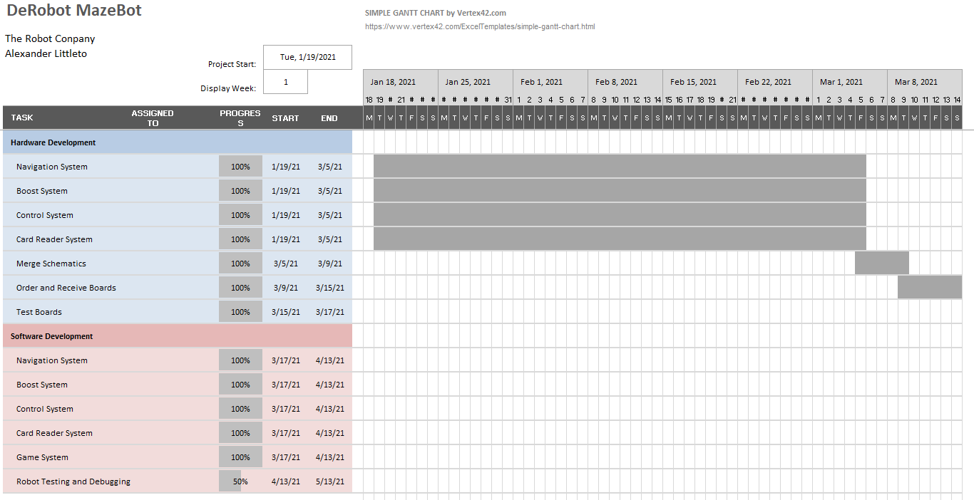
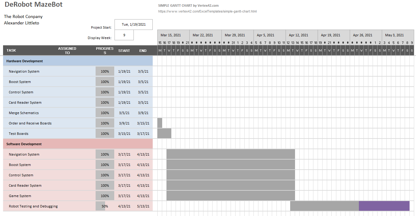
Figure 4/5: Project gantt chart
Burndown and/or Percent Complete
As of the end of our final demonstration on 5/13/2021 the robot is early in the testing and debugging phase which is the time after all subsystems have been tested and the integration between all subsystems as a whole are tested.
The DeRobot project started out on time with getting the robot and hardware design finished and fully tested the the 17th of march. However the software portion of the design took much longer than expected and took up an extra 3 weeks of time, leaving only 1 week for the entire testing of the robot.
Concept and Preliminary Design
In this section the background knowledge and research conducted, along with any innovative ideas, and the conceptual design of the DeRobot MazeBot project is shown here. First the background knowledge and research done in order to complete the project is displayed. Afterwards, the innovative features of the DeRobot MazeBot is shown. Finally the complete conceptual design for the DeRobot MazeBot is shown.
Literature Review
In this section the background knowledge and research conducted, along with any innovative ideas, and the conceptual design of the DeRobot MazeBot project is shown here. First the background knowledge and research done in order to complete the project is displayed. Afterwards, the innovative features of the DeRobot MazeBot is shown. Finally the complete conceptual design for the DeRobot MazeBot is shown.
Card Reader System
There were three major problems that prevented us from moving forward with the software for detecting the cards: getting RGB data from our sensor without a library, converting that data in HSV, and getting the HSV code to work without floating point math. First, the color sensor module we were using (TCS37725FN) did not have a professionally created library. Our sensor was open-source in the sense that it came from the same family of sensors as anothe popular model (TCS34725). We knew that this particular sensor had its own breakout board, source code, and library from Adafruit (among others). However, the one we chose enabled us to use its built in proximity detection for wall detection, which was one of our requirements. We got permission early on in the semester to have this sensor do “double duty”. It would be used by both card reader and navigation subsystems. Therefore, if we wanted to continue using the TCS37725FN, we were going to need to work around the lack of a library. This led us down the idea of using a bare metall programming approach. This is when you program the sensor directly using its built in registers. With this in mind, we scoured the internet to see if there was anyone doing this type of programming on our color sensor. This is when I discovered our first major breakthrough, which was a YouTube mbed tutorial playlist by a user named “Bme Builds”. More specifically, videos 8.4 to 8.7 were especially helpful because he provided a walkthrough of understanding the basics of I2C, how to read and interpret the datasheet, and a walkthrough for programming our TCS34725 sensor using a bare metal approach. It sounded too good to be true. Indeed, the process was not as straightforward as copying and pasting the code. Since the content creator was using a different microcontroller, I had to view his video from an agnostic approach. That is to say, I had to extract the general process, reinterpret it using Arduino code, and debug it until I got the same results. It was tedious at first, but our group was eventually able to create a successful alternative.
Now that we have a way to extract the RGBC data from our color sensor, we had to do two things. First, we needed to get the multiplexer working so that we could communicate with three of these TCS37725 sensors on command. For that task, I found Adafruit’s documentation on their 8-1 mux to be very helpful. This is because it was very similar to the mux we were using on our front hat board. The second task was that we had to find a way to convert it into HSV (Hue, Saturation, Value) color space in order to separate the chromacity (color information) from the brightness information (a much more daunting task). This approach had the advantage of allowing us to check for a single hue threshold as opposed to checking three thresholds for the R, G, and B channels. It also avoided the pitfall of having to create a manual calibration system for the sensor, as some users online, such as “Unexpected Maker”,have found helpful. If you want to check out his solution for calibrating the TCS34725 color sensor to get more accurate reading, click here. However, we did not use his method as it would be unnecessary using the HSV approach. The second biggest problem we encountered was finding reliable code for calculating HSV in Arduino. There are some user created libraries for this, but I wanted more control over the process so that I have a working understanding of the code. Eventually, we discovered that this website called Rapidtables.com had a very nifty calculator to convert between RGB to HSV. They also had a convenient set of formulas for converting from RGB to a normalized HSV (from 0 to 1). The primary issue with these formulas is that normalization meant we needed to use floating point math to get our results. Our project manager Alex explained to us that this is an inherently slower and computationally expensive process compared to integer math. And since our priority was to detect the cards as fast as possible, we opted to go for the more computationally efficient approach. Therefore, I had to find a way to calculate HSV without floating point arithmetic. While I tried modifying the code directly, Alex had discovered a forum post on stack overflow that looked promising. The question in the post was looking for the exact same code I had been searching for, but in Python. For your reference, the code can be found here. After looking at the code for a bit, it seemed manageable. So I began the process of converting the Python code line by line into C for Arduino. I wanted to convert the raw RGB data to a value between 0 and 255. I ran into several bugs along the way, and I had to create test bench code and compare it to the original RGB to HSV code from rapid tables as well as some old test bench code that Alex had from a previous project. After comparing the test bench and the original code, I decided to look at Adafruit’s TSC34725 library on GitHub to see how they got their RGB values from 0-255. Sure enough, on the file Adafruit_TCS34725.cpp, lines 337 – 360, it showed their conversion process. I had to calibrate the raw RGB channels by dividing by the clear channel value, then multiply by 255. After that, the RGB to HSV code worked wonders. I just had to test it, change the thresholds, integrate it into our modularized software system, and get it working on the 3DoT. Still a lot to do, but the most pertinent resources used for getting the card reader to work can be found in this section.
In this section the background knowledge and research conducted, along with any innovative ideas, and the conceptual design of the DeRobot MazeBot project is shown here. First the background knowledge and research done in order to complete the project is displayed. Afterwards, the innovative features of the DeRobot MazeBot is shown. Finally the complete conceptual design for the DeRobot MazeBot is shown.
Control System
The control system is based off of the control system for an automated car parking robot that was developed by the developer of the control system, which is also referenced in the game system section of this paper. The most useful component of the control system is how the control loop runs in order to let multiple subsystems control the motor.
Another resource used by the control system is the firmware for a dc motor controller that was developed by the developer of the control system. The controller can operate in several different modes such as constant speed, position, current, and voltage. However, the most useful component is how to interface with a dc motor controller ic in order to have the motor move forward and backwards at set speeds and how to make the controller stop by braking or by coasting.
Boost System
The boost system design was generated using the TI Webench Power Designer online tool. This tool generated a suitable 12V boost convertor for the project. This 12V boost convertor was then used to charge a supercapacitor. The output of the capacitor was then controlled by a high side switch which can be controlled by a digital output on the 3dot.
Game System
One of the largest references that was used in the development of the game system software was the code and hardware designs that were used for an automated car parking robot, which had to follow a colored line and follow directions from a computer that calculated the shortest path for all of the robots. The robot that this project references is very similar to the DeRobot system. They both use the same series I2C multiplexers and color sensors and they both use the same software strategies for pathfinding and maze storage. The only difference is that the car parking robot had much more memory and processing power than the 3DoT, which meant that the code had to be optimized in order to run on the 3DoT.
Another reference that was used is some final exam code from a data structures and algorithms class that was previously taken. The final project was to make software that found an optimal path through a maze. The only issue is that the program is optimized for processing speed and not memory footprint, which had to be changed in order to fit into the 3DoT board.
Conceptual Design / Proposed Solution
Card Reader System
The card reader subsystem shares the front hat shield with the navigation susbsytem. More specifically, it utilizes three TCS37725FN Color (RGBC) Sensors with Proximity sensing capability via IR LED. It runs on 3.3V and comes in an SMD package, which are requirements consistent with our use of the 3DoT board, the need to create a custom shield with SMD components, and the need for ease of troubleshooting via visual inspection after manufacturing. The front hat board also features two white LEDs (one between each sensor). These LEDs are needed to increase the brightness of the cards, which will improve the strength of our values when detecting cards. We will also need current limiting resistors (165Ω) to limit the forward current of the LEDs to 20mA. Moreover, the output of the color sensor is I2C, but it does not have a programmable slave address. Thus, we will need an I2C multiplexer to have full control of all three sensors without them inteferning. The companion device we chose was the TCA9546A, which is a low voltage 4-channel I2C switch with Reset. It is relatively inexpensive and has the minimum number of channels. Furthermore, the card reader subsystem will be detecting solid colored cards. First it will initialize all three sensors; the it will use the center color sensor to collect raw RGBC data; after that it will convert the raw RGBC to HSV. Based on teh threshold for the hue, it will detect one of nine card types, which the card reader subsystem will return to the Game Software Module via I2C.
The list of colors used to encode the card data (Monster, Treasure, etc.) for the maze are outlined in the chart below.

Table 4: HSV color selection table
We chose 9 equally spaced hue values to correspond with all the options for the cards: 4 monster tiers, 4 weapon tiers, and treasure. I used the HTML Color Picker Tool from rapidtables.com to help me find the RGB and Hex Codes. These cards will be substituted in place of the cards shown in PlayingCard.pdf. Note, the presence of a card will be determined by the saturation and value detected by the color sensor. If the saturation and value are below a certain threshold, then no card is detected. Otherwise, one of the 9 card values above will be chosen.
TCS 37725 Dual function color sensor with the feature of IR sensing. Enables more than one approach to attempt project design of navigating through the maze.
Control System
The control system utilizes state machines and a variable based control system in order to turn the rover and to allow the navigation system to align the robot.
A variable based control system works by having all functions used to control the robot set variables rather than control the motors directly. All commands and calculations are done inside of a loop that has a controlled timing. The benefit of the variable based control system is that commands take little time to execute since there are no motor commands being sent out when a turn request is sent.
Once the navigation and game systems change the command variables in order to move the motors, the control system state machine runs at a constant rate. The state machine has two portions which is the movement control and the turn control systems. The movement control system looks at the movement control variable that is set by the game system, and moves the robot in the set direction. The turn control system contains a state machine that is used to turn the robot. The first state of the turn control system is to stop at the center of a square tile. Once the robot has stopped at the center of a square tile, the second state begins which rotates the robot until a timer has elapsed. The last state sets the robot to move forwards again and resets the state machine to its original state.
Boost System
Use the LMR62421 Boost convertor with suitable components to create a 12V boost to charge the supercapacitor.
Game System
The game system utilizes three concepts in order for it to function: breadth fist search, graphs, and state machines.
The entire robot game system is comprised of a state machine with two inner state machines implemented inside of each state. The highest level state machine is a switch between the maze mapping mode and maze execution mode. This state machine toggles between the two modes upon power cycling the 3DoT board which is done by reading and toggling a bit in EEPROM at startup. The maze mapping state machine contains two states: one for when the maze is actively mapping which then the robot follows the procedure below, and another for when the maze mapping is finished which makes the robot stand still.
The maze execution state machine has 5 states. The first state is the initial move state which moves the robot forwards to get the state of the current room. After the robot has moved the robot switches into the second state which makes the robot move randomly through the maze until the robot can match a pattern of squares to a unique pattern of the maze that in is the robot’s memory. The third state starts after the initial position is found which makes the robot repeatedly collect the closest collectable card until no cards are left. After no cards are left, the robot goes into the fourth state which makes the robot find the closest exit and leave the maze, which completes the game.
The second concept used in the robot is a graph. A graph is a collection of vertices, each with their own number, that are connected to other vertices. In this case, each square and it’s encoded position will be a vertex, and each connection represent a place where a wall is not present. The graph for the pre encoded maze can be shown at an earlier blog post here.
The reason why a graph is used is that the graph is in a structure in which pathfinding can be easily done.
The final concept used is breadth first search which is used to find the shortest path between the robot and any square on the maze. The way that breadth fist search works is that first the robot checks to see if all neighboring squares to see if the destination tile is present. If not, then the robot checks the neighbors of the previously checked squares. The previous step is then repeated until the destination card is found. Finally, to follow the path the robot follows the tiles that the algorithm searched in order until the destination tile is reached.
System Design / Final Design and Results
System Block Diagram
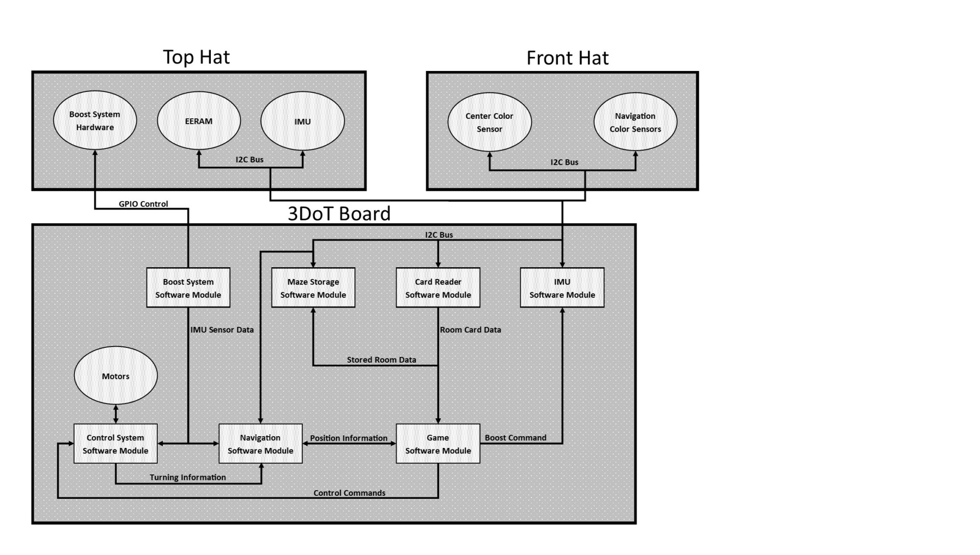
Figure 6: System block diagram
The final DeRobot MazeBot is constructed from 3 boards. One of the boards is the top hat, which provides a place for the EERAM, IMU, and boost system hardware to reside. The second board is the front hat which contains sensors for both the navigation and card detection subsystems. Finally the last board is the 3DoT board, which contains all software on the robot and the circuitry to drive the motors on the MazeBot.
The robot as a whole has 7 software subsystems which all have individual control over one component of the robot. The boost system software module is responsible for sending out GPIO signals required to start and stop the boost system upon request from the game software. The maze storage module is responsible for storing information from the navigation and game software systems inside the EERAM in the top hat. The card reader is responsible for reading color data from the center color sensor in the front hat and returning the card type assigned to the read color to the game software module. The IMU software module is responsible for reading imu data from the top hat and sending the data to the control and navigation systems. The control system is responsible for allowing the navigation and control system to simultaneously control the motors on the 3DoT board and not notify the navigation system of when a turn is complete. The navigation software module is responsible for tracking the orientation, location, and current wall configuration of the robot. In addition, the navigation system is responsible for keeping the robot aligned with the maze walls. Finally, the game software is responsible for receiving and sending commands to other software modules in order to make the robot correctly execute the maze game.
Interface Definition
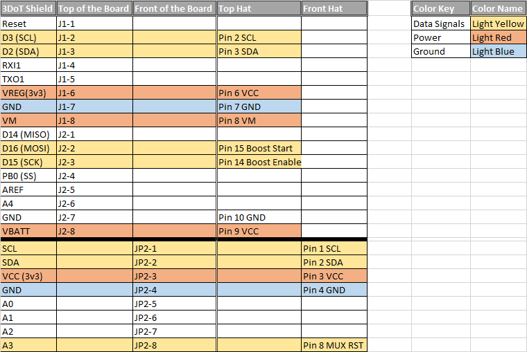
Table 5: Interface Matrix
As shown in the previous section, all devices excluding the boost system communicates through a single I2C bus. This bus is accessed though the 3DoT’s front and top headers for their respective boards.
Modeling/Experimental Results
Card Reader System
Before the front hat board was manufactured, breadboard testing of the subsystem was conducted using an Arduino Micro in place of the 3DoT board; the TCA9548PWR in place of our mux, and the TCS34725 breakout board in place of our color sensor module.
Demonstration Video: https://drive.google.com/file/d/10EAvh0UNaFZbgrVKHbfZa0SZlVZ_ZKdG/view?usp=sharing
Once the front hat board was manufactured, it was discovered that the traces for the SDA and SCL lines from the 3DoT v10 board were missing. Therefore, two small wires needed to be soldered from the top hat headers to the front hat headers to connect the SDA and SCL pins. Initial testing revealed that the magnitude of the RGBC channels for the front hat were much lower than the initial tests for the TCS34725 breakout board. The most obvious difference was the light from the LED being on. Thus, we completed the solder bridges SJ4 and SJ5 on our front hat board. This improved our values from the RGBC, and thus the HSV values as well. Now we were ready to test out the front hat sensor for detecting every type of card.
Demonstration Video 1: https://drive.google.com/file/d/1EiQN5bY_C40EjQMwhrQf4J_4VB2IWPtt/view?usp=sharing
Demonstration Video 2: https://drive.google.com/file/d/1fKq4WpWJ_kiS0jrS2PdJLp4rn4ieii1o/view?usp=sharing
In the PaperBot design one of the tasks was deciding the sensors that will enable you to journey through the maze. The sensor will have a datasheet that will give you the expected design parameters. In this example, I’m putting a TCS34725 color sensor through a test to see if it can satisfy the Navigation system requirements.
Navigation L3 Requirements (What do I Want?)
Front Sensor detection linear X span of <4cm.
Side Wall Sensor detection linear X span of <4cm.
First, I read the values with Arduino IDE using the sensor and Arduino Uno. Then, I tabulated the sensor readings to evaluate its performance and summary of requirements listed. Finally, a snap shot of the simulation is at the end of this report.
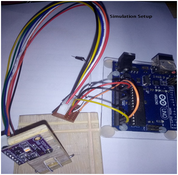
Figure8-Sensor connected to the Arduino Uno, in preparation to Arduino IDE Serial Monitor. The JST connector harness made it easier to connect to sensor and color identify the connections.
In order to read the values from the sensor it is common to find a sketch or header file with or without being part of a library that is produced by the manufacturer or multiple sources published on line. This file after it is compiled and uploaded to your Arduino board uses the Serial Monitor feature found in the IDE. The data moves fast, so timestamp selected can help keep track of the current reading. Also, set the baud rate to match your Serial.Begin line initialization instruction(TCS34725 (RGB) Sensor Code).
The manufacturer of this color sensor does a performance test similar to my experiment. They will take a solid color card at a maximum distance and record the readings. My method is similar except that I will use a white piece of paper to observe color detection by placing a marker line in its path. My marker is a Dark blue flat piece of paper (1cm x 8 cm) on top of 21.25 cm x 27.5 cm. white paper which will mimic a line in the maze. This sensor when powered on has an LED that projects light to aid in taking readings. My background lighting lamp had a higher Kelvin at above 5000, in contrast the LED on sensor was a bit warmer light temperature. You can observe in Color Temp that my LED lamp not pictured is dominating the paper’s light temperature.
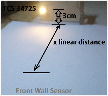
Figure 9
NAVIGATION L3 Requirements 3/15/2021
RGB testing sensor TCS34725 at a height of 3cm. showing a detection of x linear range of 6cm. regardless of angle to vertical facing downward(Figure3). Maze room has inner wall to wall 6cm-3mm width(Figure4). Reduce RGB sensor detection to <6cm. Locate center sensor to lower mounting location on bottom of PaperBot chassis facing maze.
Left and Right Wall sensors mounted to face maze(Not shown). Detection needed at <2.0cm. when mounted on PaperBot chassis..
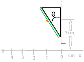
Figure10: Initially the expectation was that the sensor would be mounted at this height.
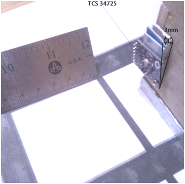
Figure11
The sensor’s linear detection measurements were over reaching past the dimensions of one room in the maze. There are the front and side walls that will be required to detect, so the goal is to read less than a distance where it doesn’t read past the walls. I’m using x in my table to indicate a linear convention, with the sensor to be the origin of zero. At every column I’m incrementing the marker further away from the base location in respect to the sensor(Table 1).
An angled installation was considered to reduce the range. To explore this option I tried holding the sensor and placing shims behind it, but these methods had drawbacks. I made an adjustable joint that helped in keeping my hand out of detection and attaining reliable values at wider angular range. The final results were that with a 3.3 volt power supply, with any theta from 0 to 45 degrees to X axis, the sensor maintains a detection of 4 to 6 cm span to paper’s surface.

Figure 12: Setup built to beused to maintain stable readings.
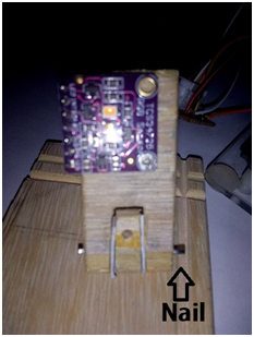
Figure13: Rudimentary joint construction with wood and pliable nail.
| TCS34725 Sensor linear X distance, at height of 3 cm.
Arduino Uno w/3.3V power supply |
White Paper
W/No marker in front of path X = 0 to 1cm |
W/Dark Blue Marker in its path.
X= 1 to 2cm |
W/Dark Blue Marker,
X= 2 to 3cm |
W/Dark Blue Marker,
X=7 to 8 cm |
W/Dark Blue Marker, X = 9 to 10cm |
| Color Temp | 5201 | 5201 | 5201 | 6100 | 6100 |
| LUX | 32.5 | 32.5 | 21.8 | 32 | 36 |
| R | 13.92 | 13.92 | 11 | 16 | 13.92 |
| G | 13.92 | 13.92 | 11 | 16 | 13.92 |
| B | 13.92 | 13.92 | 19 | 16 | 13.92 |
Table 6: Color sensor test results
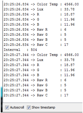
Figure14: Serial Monitor real time values with time stamp in first column of data.
Control System
In order to model the control system, a preliminary version of the navigation and game systems where integrated with the navigation system in order to see if the control flow of the program and the turn timings worked. A video of one such test is shown below:
Demonstration Link: https://drive.google.com/file/d/19fAepUyews85LLBBG5tAa6y0vmHjpejf/view?usp=sharing
Boost System
Boost switch was modeled in LTSPICE to confirm the high side switch with a MOSFET driver will work as expected.

Figure 15: LTSPICE boost system simulation
Game System
Since the game system is an entirely software based system, the game system can be run in a simulation to prove functionality. The simulation was constructed by taking the game system and writing wrapper functions for the other subsystems to test the game system. In addition, a text based maze display was constructed so that the state of the robot can be seen. Videos of both the maze execution and mapping phase simulations are shown below:
Demonstration 1: https://drive.google.com/file/d/1pEjTSF8xKM6zmLsJhQ4Se1kIZZYAZyVL/view?usp=sharing
Demonstration 2: https://drive.google.com/file/d/1c4d-DKd7bM9tJTxl2hF-rkr3DgvwQt12/view?usp=sharing
Mission Command and Control

Figure 16: Software UML Diargram
The DeRobot control system is a modular procedural programming based architecture. There are a total of 7 software subsystems on the robot all of which have their own function. The ICM20948 software module is resible for utilizing the arduino wire library in order to retrieve information from the magnetometer of the top hat. The ControlSystem is responsible for allowing the game and navigation systems to control the motors on the 3DoT board using arduino provided pwm functions. The maze storage system is responsible for utilizing the arduino wire library in order to read and write to the external memory on the top hat to let the game system store the maze. The card reader system is responsible for utilizing the arduino wire library in order to read the central color sensor on the front hat and to recognise the card from the obtained color. The boost system is responsible for enabling and disabling the boost system on command from the game system by using the arduino pin writing functions. The navigation system is responsible for position and orientation tracking utilizing the front color sensor and the magnetometer using the arduino wire library. The navigation system is also responsible for tracking the walls of the maze by reading the left and right color sensors using the arduino wire library.
Since the DeRobot system is fully automated, there is no human interface excluding the on and off power switch. The purpose of the power switch is to change the robot between the maze execution and mapping modes by toggling the power to the robot.
Electronic Design
PCB Design
The DeRobot PCB design process was a three stage process which involved schematic design, board layout and board merging. Each of the stages for both the top, front, and navigation hats will be shown below
Schematic Design
The first step of the design process is to have each subsystem produce an independently working schematics. In total there are 5 schematics which were produced, one for each subsystem. A description and image of the subsystem schematics are shown below:
Control System
During the control system schematic design phase, the control system originally was supposed to make the robot self balancing which required knowledge of the angle of the robot which required an inertial measurement unit (IMU). In addition the navigation system needed a reference to tell the initial orientation of the robot which required a magnetometer. To solve these two problems, the control system is based off an ICM-20948 9 axis IMU from invensense. The ICM-20948 was chosen specifically for it’s 9 axis capability, visually inspectable packaging, and I2C capability. Shown below in the initial schematic for the control system portion of the robot.
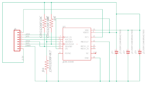
Figure 17: IMU schematic
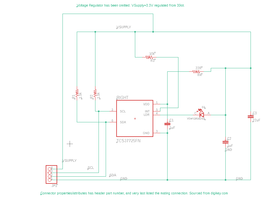
Figure 18: Navigation color sensor schematic
Boost System
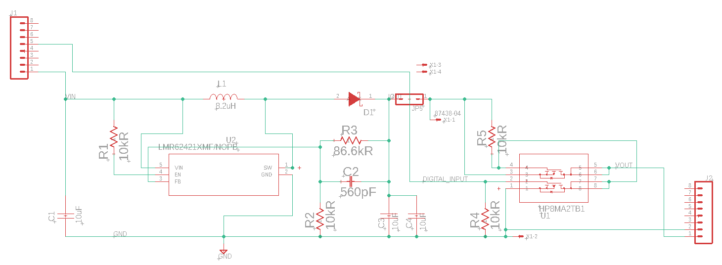
Figure 19: Boost system schematic
Card Reader System
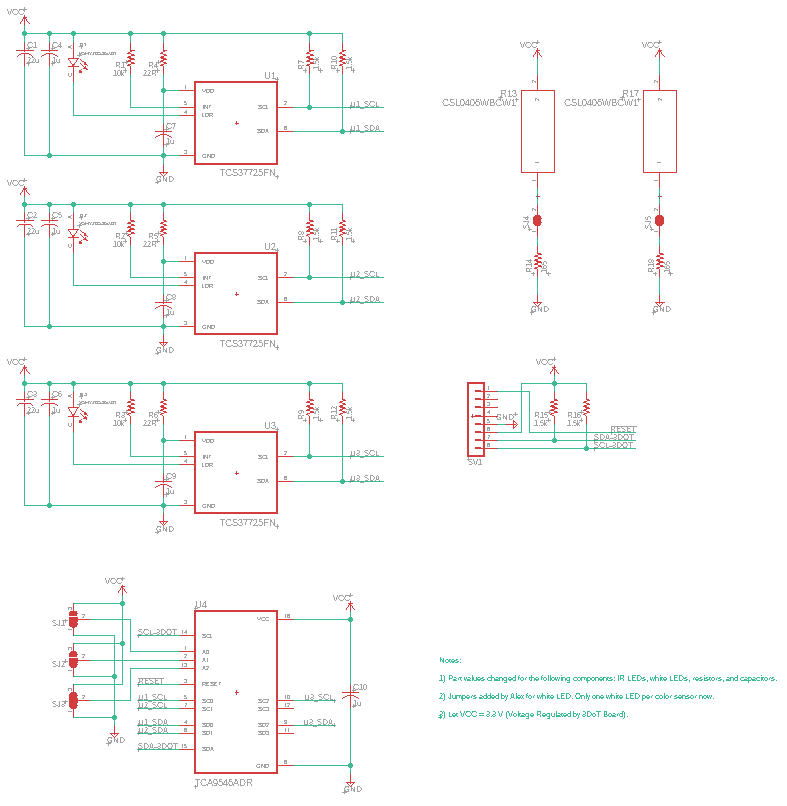
Figure 20: Card reader schematic
Board Layout
The second step of the design process is to have each subsystem be laid out on individual boards in order to accelerate the board merging process. Images and descriptions of each subsystem board are shown below.
Control System
The control system board layout process was very loose due the lack of components that were needed to get the IMU functioning. The components where all connected together as a reference for when the IMU was integrated into the top hat.
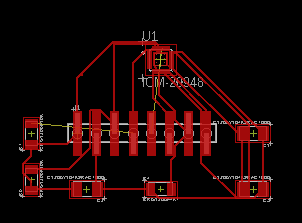
Figure 21: IMU board layout
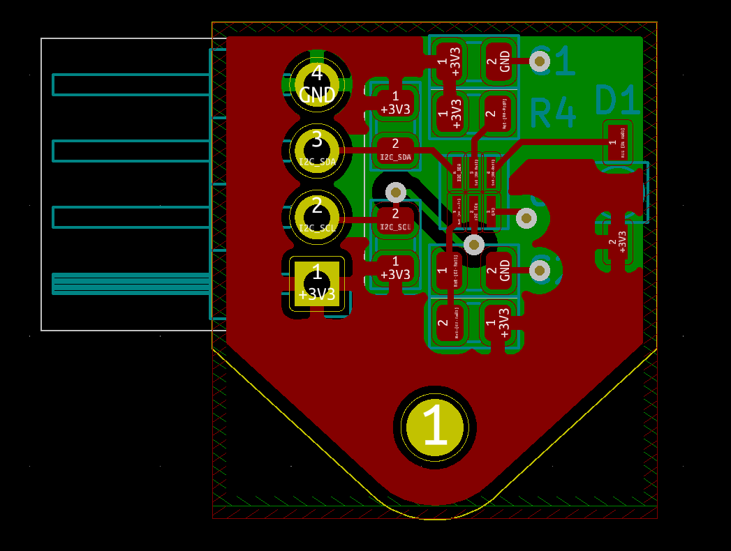
Figure 22: Navigation sensor layout
Boost System

Figure 23: Boost system layout
Card Reader System
Created with three color sensors on board. Spacing of color sensors are adjusted such that the two outermost ones lie directly above the black line that outlines the green hedge walls maze

Figure 24: Card sensor layout
Board Merging
The next step was to merge all of the designs into the designated boards. The boost, control, and game system boards were all merged into a single board that was put on the internal header of the 3DoT board, this became the “top hat”. The navigation and card reader pcbs were put on a board that connected to the front header of the 3DoT board, this became the “front hat”.
Front Hat
The front hat was the easiest board to merge since the front hat is an exact copy of the navigation system’s board. It was found that the navigation and card reading systems can utilize the same sensors in order to reduce the number of sensors on the robot and to allow for the reuse of code. The schematic and layout of the front hat is shown below.
Figure 25/26: Front hat layout and schematic
The top hat contains the control and boost subsystem hardware. In addition, some EERAM was added to the board in late development in order to let the game system utilize more memory and store the maze without the 1Kb limit that is set by the MCU on the 3DoT board. Some changes to the subsystems had to be made. For example, the imu can only put out 1.8v I2C signals where the 3DoT is a 3.3v system. This was solved by using a transistor I2C logic level converter. The schematic and layout of the top hat is shown below:
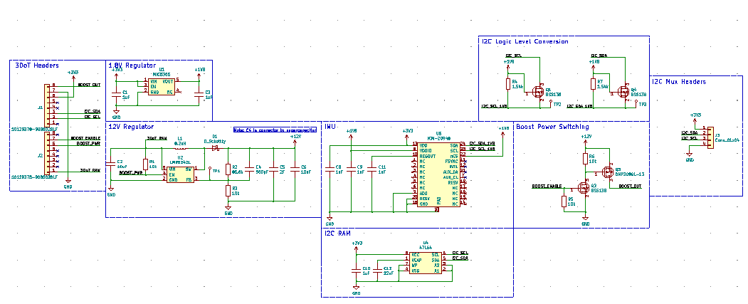

Figure 27/28: Top hat schematic and layout
Final Boards
The top hat contains the control and boost subsystem hardware. In addition, some EERAM was added to the board in late development in order to let the game system utilize more memory and store the maze without the 1Kb limit that is set by the MCU on the 3DoT board. Some changes to the subsystems had to be made. For example, the imu can only put out 1.8v I2C signals where the 3DoT is a 3.3v system. This was solved by using a transistor I2C logic level converter. The schematic and layout of the top hat is shown below:

Figure 29: Final manufactured boards
Firmware
The DeRobot has 7 subsystems, 6 of which contain firmware to interact with external hardware as described in the previous section. In this section each subsystem will describe the methods used to utilize the sensor and what information that subsystem provided to the rest of the system.
Card Reader System
Psuedocode of functions within Card Reader Subsystem:
1) InitCardReader()
- For current color sensor, currentColorSensor++
- Select channel on mux.
- Check ID register
iii. RGBC Timing Register set to Max Integration TIme
- Control Register sets Analog Gain to 1x
- Enable Register turns on sensor power and color sensor
- End loop
2) getCurrentCard()
- Select middle color sensor on mux.
- Write command code to clear data register
- Read two bytes from clear data register
- Repeat read and write process for Red, Green, and Blue data registers
- Format data to single 16-bit value
- Calculate 16-bit HSV values from 16-bit RGB values.
- If hue and saturation are below threshold
- Return No card
- Else if hue is within range 1
- Return Monster Tier 1
- Else if continued for all card types
- End if
3) updateCardReader()
- return getCurrentCard()
4) #ifdef Debug Mode
- Enables Serial print statements for troubleshooting RGB/HSV values in Serial Monitor.
Header file of Card Reader Subsystem:
#ifndef CARD_READER_H
#define CARD_READER_H
//Enumeration used to return card data from getCurrentCard()
typedef enum{
CARD_NULL,
CARD_TREASURE,
CARD_MONSTER_T1,
CARD_WEAPON_T1,
CARD_MONSTER_T2,
CARD_WEAPON_T2,
CARD_MONSTER_T3,
CARD_WEAPON_T3,
CARD_MONSTER_T4,
CARD_WEAPON_T4
}Card;
//Initialization function for the card reader
void CARD_initCardReader();
//Function to get the currently received card
Card CARD_getCurrentCard();
//Looping function, used to manage card reader hardware
void CARD_updateCardReader();
#endif
RGB to HSV function within Card Reader Subsystem:
void calculateHSV(uint16_t red, uint16_t blue, uint16_t green, uint16_t Clear, uint16_t* hsvArray)
{
uint16_t rgbMax = 0;
uint16_t rgbMin = 0;
uint16_t redPrime = 255 * (uint32_t)red / (uint32_t)Clear; //4000.0;
uint16_t bluePrime = 255 * (uint32_t)blue / (uint32_t)Clear; //4000.0;
uint16_t greenPrime = 255 * (uint32_t)green / (uint32_t)Clear; //4000.0;
uint16_t hue = 0;
if((red > blue) && (red > green))
{
rgbMax = redPrime;
}
else if((blue > red) && (blue > green))
{
rgbMax = bluePrime;
}
else if((green > red) && (green > blue))
{
rgbMax = greenPrime;
}
if((red < blue) && (red < green))
{
rgbMin = redPrime;
}
else if((blue < red) && (blue < green))
{
rgbMin = bluePrime;
}
else if((green < red) && (green < blue))
{
rgbMin = greenPrime;
}
uint16_t delta = rgbMax - rgbMin;
if(delta == 0)
{
hue = 0;
}
else if(rgbMax == redPrime)
{
hue = 0 + 43 * ((int)greenPrime - (int)bluePrime)/(int)delta;
}
else if(rgbMax == greenPrime)
{
hue = 85 + 43 * ((int)bluePrime - (int)redPrime)/(int)delta;
}
else if(rgbMax == bluePrime)
{
hue = 171 + 43 * ((int)redPrime - (int)greenPrime)/(int)delta;
}
hsvArray[0] = ((255 + hue) % 255);
if(rgbMax == 0)
{
hsvArray[1] = 0;
}
else
{
hsvArray[1] = 255*delta/rgbMax; //sat
}
hsvArray[2] = rgbMax; //val
#ifdef DEBUG_MODE
//delay(60);
//    Serial.print("redPrime = ");
//    Serial.println(redPrime);
//    Serial.print("greenPrime = ");
//    Serial.println(greenPrime);
//    Serial.print("bluePrime = ");
//    Serial.println(bluePrime);
//    Serial.print("rgbMax = ");
//    Serial.println(rgbMax);
//    Serial.print("rgbMin = ");
//    Serial.println(rgbMin);
//    Serial.print("delta = ");
//    Serial.println(delta);
//    Serial.print("hue = ");
//    Serial.println(hue);
//    Serial.print("modified hue = ");
//    Serial.println(hsvArray[0]);
#endif
return;
}
The navigation system reads sensor data by I2c communications of MUX on front shield. Using this information executes the following functions to play the maze game://initializes navigation system
void NAVIGATION_initNavigationSystem()
// set bit to indicate mapping modevoid NAVIGATION_setMappingMode ()
// get square position on maze as 8bit
uint8_t NAVIGATION_getSquarePosition()
// set square position
uint8_t NAVIGATION_setSquarePosition(uint8_t squareIndex)
// uses magnetometer to find the cardinal direction of robot
CardinalDirection NAVIGATION_getCardinalDirection(xyzArray)
//input parameters of CardinalDirection and direction and return LocalDirection
LocalDirection Navigation_CardinalToLocal(CardinalDirection direction)
// using LocalDirection and CardinalDirection give a turn hint to control system

void NAVIGATION_giveTurnHint(LocalDirection CardinalDirection)
// using CardinalDirection and direction give a turn hint to control system

void NAVIGATION_giveTurnHint(CardinalDirection direction);
// identify s walls when entering a new room
int8_t NAVIGATION_getWallConfig()
//uses PID to maintain robot in between walls

void correctMovement()
//main loop of navigation system

void NAVIGATION_updateNavigationSystem()
//I2c communications to retrieve sensors' data

uint16_t getColorClearData(uint8_t sensorID)
In the following void control function, I will explain its execution.
-----------------------------------------------------------------------------------
FHL = getColorClearData(0); // get clear value on left sensor
FHR = getColorClearData(2); // get clear value on right sensor
static double setpoint = 0; // set point initialized and  is 182
static double updatePID = 0.0;
if (updatePID >= millis()) { // if update is greater or equal to time the sketch runs for
}

int positioN = 0; // initiailize
static int lastpositioN = 0;
//----------------------tuning---------------------------------------
//Tuning start from all gains: Kp,Ki,Kd=0, Tested Values .05,.025,.025|.015,.007,.007|.035,.017,.017
double Kp = .30; // Turn up to oscillating, reduce to stop + 20%. Tuned Value=.0005
double Ki = .0000; // increase until instable, back off slightly Tuned Value=.00004
double Kd = .0000;  // start from 0, slowly increase to improve response Tuned Value=.0001
//---------------------tuning----------------------------------------
const double startGuardMin = 0; //min sensor reading for PID
const double startGuardMax = 255; //max sensor reading for PID
int baseSpeed = 110; //40% of max speed 255
int speed = 0;
positioN = (FHR - FHL); // -a=FHL b=FHR  // left motor negative  if positive increases speed on A motor
double error = 182 - positioN; // how bad are we doing? e(t), setpoint=182, processValue is sensor readings
double propT = Kp * error; //How far from actual if plotted? Kp will be a tuning value
static double iTerm = 0;
iTerm += Ki * error; // Ki unit time(Ki=Ki*dt). += adds value of right operand to a variable assigns result to variable
iTerm = constrain(startGuardMin, iTerm, startGuardMax);
double dTerm = Kd * (positioN - lastpositioN); //kd unit time(kd=Kd/dT)
lastpositioN = positioN;  //
------------------------------------------------------------------------------------------------
The first two lines attains the sensor values, followed by initialization of variables. Then the gains are initialized with tuning values that are critical to the function of the PID.
Third, initialize the variable for startGuard that is a safeguard against loss of information needed for the PID to restart with values to function when cycling power switch.
Fourth a difference is taken from the left and right sensors, which is subtracted from setpoint which is the target value. In this function our target value is 182, which is value when the sensor is directly above the wall. This subtraction will produce the error, and input into the proportional term and integral.
This information is stored into position which becomes a new starting point.
S
speed = round(propT + iTerm + dTerm); // process input. summation. Round number to not use float if (FHR > FHL) {
motorAspeed = baseSpeed + speed; // will decrease speed if negative
motorBspeed = baseSpeed - speed; // will increase speed if negative
}
else if (FHL == FHR) {     motorAspeed = speed; //
motorBspeed = speed; //
}
else if (FHL > FHR) {
motorAspeed = baseSpeed - speed; // will decrease speed if negative
motorBspeed = baseSpeed + speed; // will increase speed if negative}
}
if (motorAspeed > 220) { motorAspeed = 150; } //over limiter on MotorA
if (motorBspeed > 220) {motorBspeed = 150;} //over limiter on MotorB
if (motorAspeed < 30) { motorAspeed = 30;} //under limiter
if (motorBspeed < 30) { motorBspeed = 30; }//under limiter

-------------------------------------------------------------------
In this next set of lines, my if else statement, the speed is produced which will be used to analog write to the motors the desired speed. Analog Write Arduino instruction can be imagined as pressing an accelerating pedal on a car. My value range is 0 to 255. In our statement we aren’t going to max 255, just keeping the robot at a moderate speed. Last, our over and under limiters are necessary because our function will produce values beyond our speeds, therefore this constrains our values to meet our demands.
Game Software System
The maze storage subsystem is responsible for reading and writing information from the external EERAM module upon request from the game system or navigation system. The information provided to the game system included wall configuration storage, card configuration storage, and data tag storage. The information provided to the navigation system was imu magnetometer result storage. The services provided to these two subsystems is shown in the header file below:
//Gets the wall configuration of the given square
uint8_t MAZE_getSquareWallConfig(uint8_t squareIndex);
//Sets the wall configuration of the given square
void MAZE_setSquareWallConfig(uint8_t squareIndex, uint8_t wallConfig);
//Gets the square configuration of the given square
Card MAZE_getSquareCardConfig(uint8_t squareIndex);
//Sets the wall configuration of the given square
void MAZE_setSquareCardConfig(uint8_t squareIndex, Card card);
//Gets the data tag of the given square
uint8_t MAZE_getSquareTag(uint8_t squareIndex);
//Sets the data tag of the given square
void MAZE_setSquareTag(uint8_t squareIndex, uint8_t data);
//Stores the orientation of the maze
void MAZE_setMazeOrientation(uint16_t xAxis, uint16_t yAxis);
//Stores the orientation of the maze
void MAZE_getMazeOrientation(uint16_t* xyAxisArray);
//Clears the data tags of all squares
void MAZE_clearSquareTags();
The data inside the EERAM was stored is a few different ways. Since the wall configuration and card configuration only take 4 bits each to store, the wall configuration and card configuration was stored in the same byte. The card configuration resided in the 4 most significant bits of the stored byte and the wall configuration resided in the 4 least significant bits. The address of the square data tags and the wall/card configuration inside the EERAM module was based off of the address of the square in the encoded maze, the equation to find the address of the data is shown below:
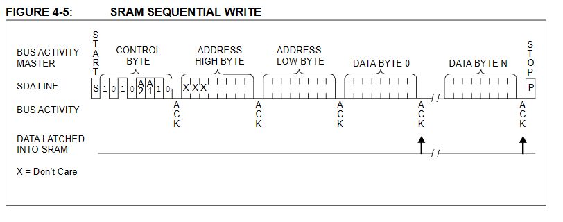
Figure 30: Sequential write procedure (from 47L64 EERAM datasheet)
squareAddress = squareIndex*2 + dataType;
Where dataType is 0 when obtaining the wall/card information of a square and 1 when obtaining the data tag of a square. The orientation data is stored at the top of the memory table in big endian format.
The EERAM is accessed using I2C with the address 0x51. To write to the EERAM, an I2C start bit is sent along with the device write address. Then a 16 bit memory address is written from the MSB to the LSB. Afterwards the data for the set address is written and a stop bit is sent. The signal diagram for the write sequence used is shown below.
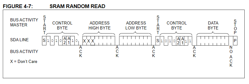
Figure 31: Sequential read procedure (from 47L64 EERAM datasheet)
To read from the EERAM, an I2C start bit is sent along with the device write address. Then a 16 bit memory address is written from the MSB to the LSB. Afterwards, a repeated start is sent along with the device read address. The data is then transmitted by the EERAM until a stop bit is transmitted. The signal diagram for the read sequence used is shown below.
Control System
The IMU subsystem is responsible for obtaining and reporting data from the top hat’s IMU to the navigation and control system. The imu subsystem is a simple function based system which has functions to initialize the imu and obtain the acceleration, change in orientation, and magnetic field of the imu. The functions of this subsystem are shown in the header below:
void ICM20948_initSensor();

void ICM20948_getAccel(int16_t* xyzArray);

void ICM20948_getGyro(int16_t* xyzArray);

void ICM20948_getMag(int16_t* xyzArray);
To write to a register in the imu an I2C start bit along with the device write bit is sent. Afterwards the address of the register is written which is then followed by the new value of the written register. The write process is then terminated by sending a stop bit. The write process of the ICM29848 is shown below:

Figure 32: Single write procedure (from ICM20948 datasheet)
To read a register from the icm20948, a start bit with the device write address is transmitted. Afterwards, the address of the read register is sent. Then a repeated start bit is sent along with the device read address which then the device transmits data until a stop bit is sent. The read process is shown in the table below:

Figure 33: Single read procedure (from ICM20948 datasheet)
The process to initialize the ICM20948 goes as follows. The magnetometer and IMU are first set by writing to REG_MAG_CNTL2/3 and REG_IMU_PWR_MGMNT_1. After a short delay to let the IMU and magnetometer initialize, the clock source for the IMU is selected by writing to REG_IMU_PWR_MGMNT_1. The accelerometer and gyroscope are then enabled by writing to REG_IMU_PWR_MGMNT_2. The ranges of the accelerometer and gyroscope are then selected by writing to REG_IMU_ACCEL_CONFIG and REG_IMU_GYRO_CONFIG_1. Finally the magnetometer sample rate is selected and enabled by writing to REG_MAG_CNTL2.
To read from the accelerometer and gyro, each result has 2 registers for the high and low bytes of the result. The two registers are read using the process described above and then bitwise or’ed together into a 16 bit variable. To read from the magnetometer, the same process is followed except that a different device address is used.
Describe and document the code implementing the firmware modules defined in the “Mission Software” section. Specifically, how the code controls and provides feedback (telemetry) for the sensors and actuators defined in the introduction to the “Electronics” section.
Provide Pseudo-code and/or flowcharts as well as short C++ samples to help illustrate the firmware. You should go into detail about any key aspects (such as shifting the center of gravity, running two motors 180 degrees out of phase, or reading of EMG sensors) of the design.
All Arduino and C++ code samples must include descriptive comments.
Mechanical/Hardware Design
I was doing an interference analysis between our 3DoT board + top hat assembly and the PaperBot chassis when I discovered that the back panel of the chassis prevents our assembly from fitting properly. More specifically, the 3DoT board sticks out approximately 1 cm with this interference, as shown in Figures 34 and 35.

Fig. 34 Back panel of the chassis hits the header of our front hat board. However, even if this header was removed, it would still have about 7mm of interference with the board itself, as shown below.

Fig. 35 Bottom view of PaperBot chassis and our 3Dot board + front hat assembly interfering with the back panel of our chassis.
Therefore, to remedy this issue, I modified the back panel of the PaperBot chassis CAD file from Jaap to allow the 3DoT board to slide fully into the side grooves as intended (See Figure 36).
Back Panel: Iteration #1: Square window is extended closer to screw holes to accomodate width of top hat board, headers, and jumpers. ”Bridge” above switch access hole is made smaller such that the bottom of the window is flush with the top edge of the bottom pair of rectangular holes.

Fig. 36 Isometric view of first iteration of modified 3DoT chassis back panel in Autodesk Inventor.
In Figure 37, it is apparent that the fit of the holes was perfect, as expected. I did not need to change their size or location. On the other hand, the areas marked in white still showed interference with the top hat board. As you can see, I ended up removing the bridge from the center to accommodate the top hat board. I made sure to increase the tolerances on the upper right hand corner next to the screw hole on the right hand side (RHS). This just involved removing a fillet from that corner, which removed enough material to accommodate the jumper on the RHS.

Fig. 37 First 3D printed iteration of 3DoT chassis back panel. Second interference analysis revealed that the front hat still hit areas marked in white.
Back Panel: Iteration #2: I moved the bridge up for stability, while making the window smaller. I decided to keep the window for two main reasons. First, it provided access for users to move the motor cables while assembling the robot. This is crucial as the small size constraints make it easy for the motor cables to get tangled with the inductor on the top hat, which adds unnecessary stress to the motor cables. Second, it saves filament (I’m not made of money).
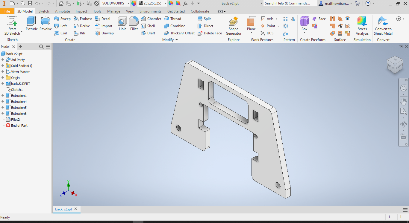
Fig. 38 Isometric view of second iteration of modified 3DoT chassis back panel in Inventor. It was then exported as an STL file to prepare it for the slicer software.

Fig. 39 STL file of second iteration back panel is imported into Ultimaker Cura, my slicer software of choice. Here, I select my printer setting such as infill percentage, nozzle diameter, and layer height. Then I slice the program, which saves gcode for my file, which I can upload to an SD card to plug into my printer. The gcode is like an executable file that tells my printer all the location and timing information it needs to create my 3D part.
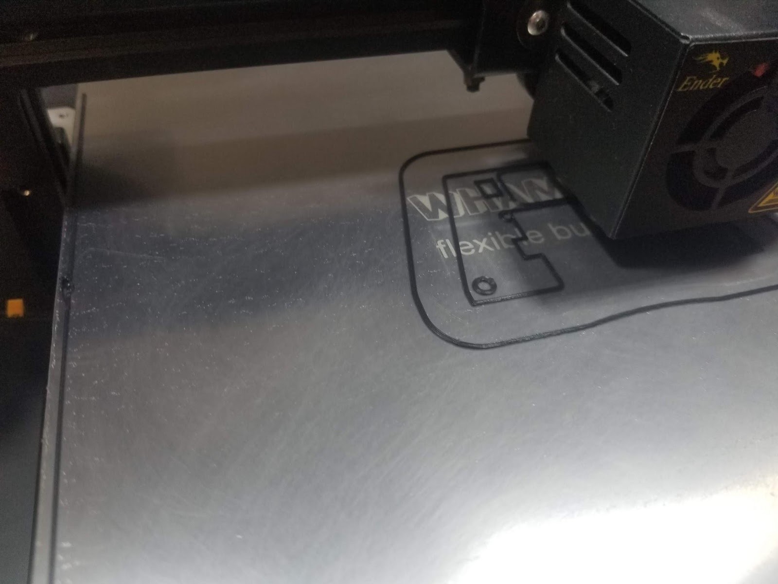
Fig. 40 Second iteration of back panel for 3DoT chassis being 3D printed on my Creality Ender 3 3D printer. Total print time: approximately 1 hr with 20% infill and 0.1mm layer height.
The design of the 3D object for the back panel can be seen in Figure 39. Furthermore,a snippet of the rapid manufacturing process can be seen in Figures 37 and 40. In Figure 41, we can see the second iteration of the back panel fully printed and attached to the 3Dot chassis.
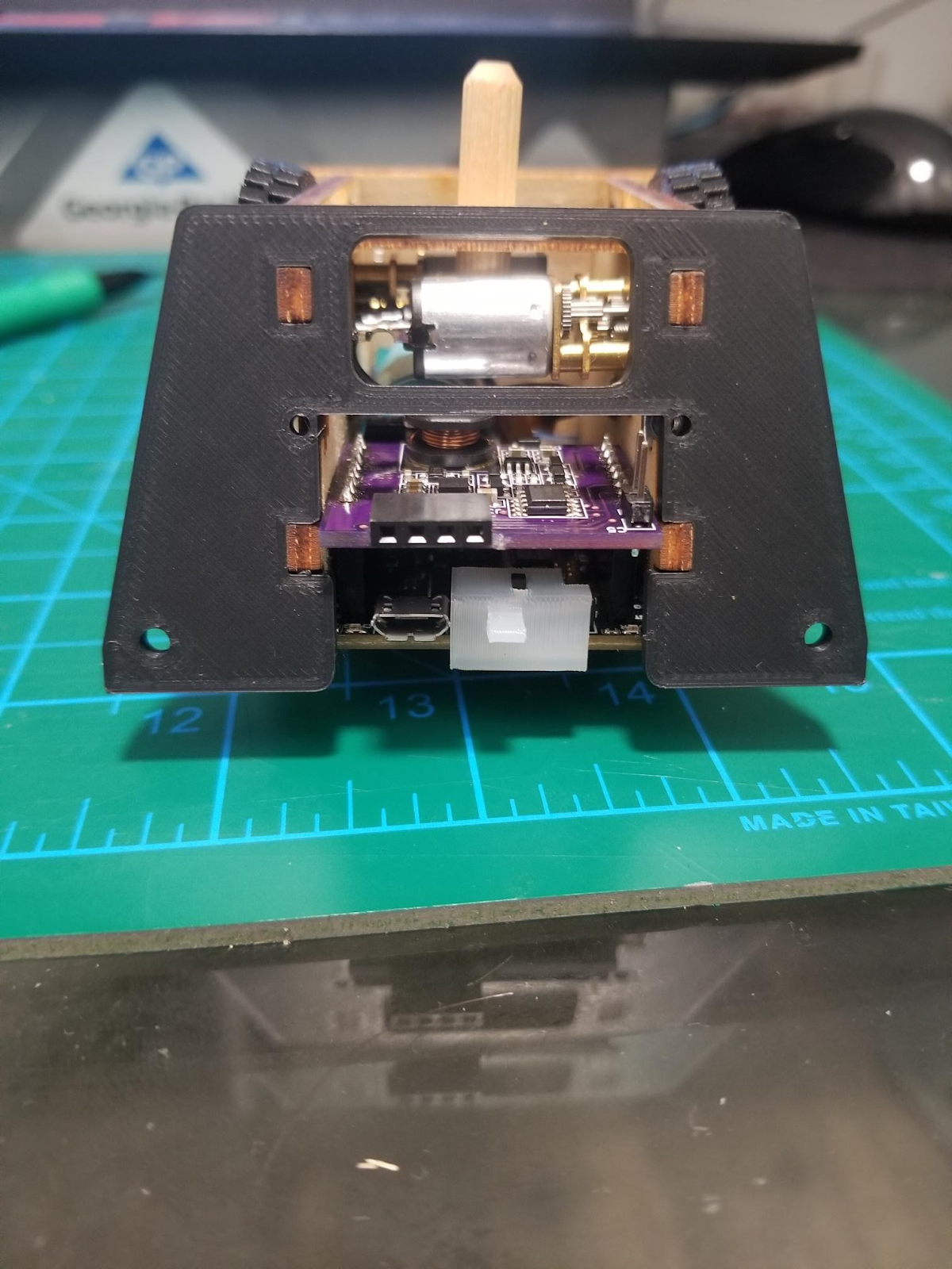
Fig. 41 Second iteration of 3DoT chassis back panel 3D printed and assembled to the rest of 3DoT chassis. No more interference between 3DoT board and back panel.
Now that we have successfully modified the back panel, let us solve the issue of the caster wheel. Recall that when Diana (our original Control Systems engineer) left our group, we went to our back-up plan, which is using the caster. However, the dimensions of our front hat make it impossible to use the default “shelf spring lock” (the part of the chassis that holds the caster in place) as intended. Please refer to Figures 42 and 43 for a more detailed look.

Fig. 42 Front hat board (bottom) and original shelf spring lock (top) are shown side by side for a size comparison.

Fig. 43 Front hat board (bottom) and original shelf spring lock (top) are shown assembled onto the 3DoT chassis. Notice that the caster wheel holes are directly above the front hat board, which does not allow us to use the caster as intended.
Shelf spring lock: Iteration #1 and #2:Thus, we decided to also 3D print a modified version of Jaap’s shelf spring lock that extends the location of the caster mounting holes for our front hat board. In Figure 11, we can see the modified 3D model of the shelf spring lock.

Fig. 44 Isometric view of second iteration of our modified 3DoT chassis back panel in Inventor. The second iteration has the same outer dimensions as the first iteration. I just made the holes a little bigger because the tolerances were tight enough to flex the caster wheel holder, which made the ball bearing fall out very easily. It was then exported as an STL file to prepare it for the slicer software and printed like before.
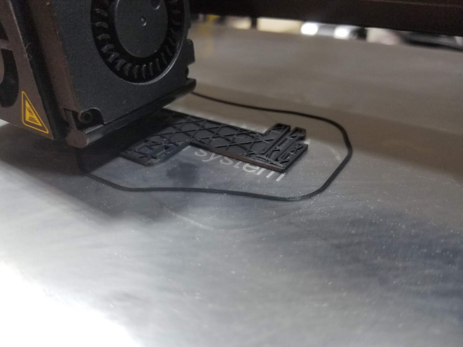
Fig. 45 3D printing of second iteration of shelf spring lock in progress.

Fig. 46 Final assembly of modified PaperBot chassis with modified shelf spring lock anf back panel. Now, our modified PaperBot chassis has no interference with our 3DoT board + top hat assembly.
A snippet of the manufacturing process for the modified shelf spring lock can be seen in Figure 45. It was printed with the same setting as the back panel. The total build time was just under 1 hr. The fully assembled version of our modified 3DoT chassis can be seen in Figure 46. After they were tested to work on my robot, I sent the STL files to Thomas so he could print and distribute them to the rest of our group.
Verification & Validation Test Plan
Card Reader System
| Requirement | Paragraph | Shall Statement | Success Criteria | Verification Method | Results | Pass/Fail |
| 2.1 | Card Reader
System |
The card reader system shall construct hardware and software required to detect and report any cards that are directly underneath the robot. | 1: Prior to the mapping phase, the system runs a function that tells the user via the serial monitor when all three color sensors in the front hat board have been initialized. | Test | 1: First iteration of for loop Serial print statements consistently not showing in Serial monitor. However, the internal counter indicates all three color sensors were initialized. | PASS |
| 2.2 | Card Reader
System |
The card reader system shall successfully detect a card within a square before the robot leaves that containing square. | 1: The system detects and identifies the colored card before the color sensor on the front hat board exits the current room while traveling at max speed without the help of the boost system.
2: System runs a function that displays (via Serial monitor) the card type detected with corresponding timestamp. |
Test | 1: Testbench modified to run motors forward without delay while collecting card data. It is able to detect three cards sequentially in three different rooms while running at full speed as defined in our control system. After looking at footage, the system detected the card within the given room.
2: Serial monitor displays RGBC, HSV values, Card Type, and Timestamp for corresponding demonstration |
PASS
PASS |
| 2.3 | Card Reader
System |
The card reader system shall detect all cards with no false positives or false negatives within 1 run of the maze. | 1: The system detects at least one instance of every card type (Monster Tier X, Weapon Tier Y, and Treasure) successfully.
2: System runs a function that displays (via Serial monitor) the card type detected with corresponding timestamp. |
Test | 1: All card types detected with front hat connected to 3DoT board; no false positives or negatives detected using solid colored cards. Bridges not tested as they are not supposed to be encountered by the center color sensor.
2:Serial monitor displays RGBC, HSV values, Card Type, and Timestamp for corresponding demonstration |
PASS
PASS |
Table 8: Card reader verification matrix
Test software with Arduino IDE, robot, and Serial Monitor. Upload software on robot , trial run on maze and visual inspection of results. Testing with Arduino Uno and break out boards and comparing results to 3Dot and hardware.
| Requirement | Paragraph | Shall Statement | Success Criteria | Verification Method | Results | Pass/Fail |
| 3.1 | Navigation System | Navigation system shall construct hardware and software required to keep the rover aligned with the maze grid deviation not to exceed more than 1/2 of the robot’s width(<3cm). | 1: System moves through a 16 square long hallway (width of maze) maintaining less than 3cm deviation from center of room. | Test | . | PASS |
| 3.2 | Navigation System | Navigation system shall provide the room wall configuration encoded in the format described by the encoded made document by the time that the robot has left the square. | 1: The system returns the correct room type by the time the system exits a maze square. | Test | PASS | |
| 3.3 | Navigation System | The navigation system shall track the position and orientation of the rover throughout the maze. | 1: The system correctly reports the initial orientation of the rover for the entire duration of the game.
2: The system correctly tracks the orientation of the rover with assistance from the control system for the entire duration of the game. 3. The system correctly reports the correct position after being given a correct initial position for the entire duration of the game. |
Test | PASS
Fail Fail |
Table 9: Navigation system verification matrix
Control System
The control system tests are mainly testing the ability for the control system to allow the navigation and control systems to change the state of the motors. This was done by taking the developed navigation and game systems and testing to see if the robot moves in accordance with their commands. The result of these tests are shown in the verification matrix below.
| Requirement | Paragraph | Shall Statement | Success Criteria | Verification Method | Results | Pass/Fail |
| 4.1, 4.2, 4.4 | Control System | The control system shall construct hardware and software required to turn and move the robot in accordance with commands sent by the maze system. | 1: The system turns in the requested direction by 90 +-22 degrees when requested | Test | Robot when requested turns within about 10 degrees of the requested angle. | PASS |
| 4.3 | Control System | The control system shall notify the navigation of when a turn is complete. | 1: The navigation system reports the correct direction after a turn has completed. | Test | Control system notifies navigation system when a turn is complete, allowing the robot to navigate the maze | PASS |
Table 10: Control System verification matrix
Boost System
| Requirement | Paragraph | Shall Statement | Success Criteria | Verification Method | Results | Pass/Fail |
| 5.1 | Boost System | In order to fulfill requirements L1.1, the boost system shall construct hardware and software required to speed up the robot by overvolting the motors. | By running the boost enable code we should see the robot speed up in the direction it is moving | Test | By setting the nmos gate controlling the output of the supercapacitors high, 12V flows into 5V_VM therefore overvolting the motors. | PASS |
Table 11: Boost system verification matrix
Game System
The game system validation encompases the maze storage and game software subsystems. The tests that are conducted are mostly done in computer simulation as shown previously in this post in order to isolate the game system from the rest of the robot. In addition, some full robot tests are proposed as well in order to test the integration between the game system and the robot. The verification matrix for the game system is shown below.
| Requirement | Paragraph | Shall Statement | Success Criteria | Verification Method | Results | Pass/Fail |
| 6.1 | Game System | The maze system shall construct software required to make the robot map and store the configuration of the maze. | 1: The system can store and load random maze data without data loss.
2: The system sends correct commands to other subsystems to map the maze. |
Test
(Computer Simulation) |
1: In simulations, the system saves data identical to the structure of the maze.
2: In physical tests external eeprom is able to store maze configuration across restarts |
PASS |
| 6.2 | Game System | The maze system shall construct hardware and software required to make the robot find the initial position of the robot during the calibration stage. | 1: Given a correct map of the maze, the system finds the initial position by sending commands to other subsystems. | Test
(Computer Simulation) |
Given correct data from subsystems the robot can find and report the initial position. | PASS |
| 6.3 | Game System | The maze system shall construct hardware and software required to make the robot collect all the cards efficiently and exit the maze when finished. | 1: The system collects all cards before exiting the maze
2: The system exits the maze |
Test | The system collects all cards and then exits the maze, both in simulation and physical test | PASS |
| 6.4 | Game System | The maze system shall construct hardware and software required to ensure the robot does not break “The rules of the game”. | 1.: The system does not break any rules as defined in “The rules of the game” within a single maze run | Test | The robot obeys the rules of the game at all times except for when in initial position finding mode where walls can be passed through | FAIL |
Table 12: Game system verification matrix
Concluding Thoughts and Future Work
The design of the robot work most of the time, however there is one large issue that in future generations could be improved on. Currently the maze tracking system utilizes two light sensors that lay on the inside of the walls, however the walls are not always present and the robot looses tracking during difficult turns or mapping. To fix this, the next generation could use 4 color sensors in a similar pattern to the 3DoT ir shield which has sensors on the inside and outside of the wall. If we have one wall, we would still have two sensors to track with.
As for the management of the robot, the two largest improvements that could be made is to spend less time on hardware design and more time on system engineering and software development. The reason why increasing effort on software development would help the success of the project is that while everyone in the group is well educated in making hardware, lots of time had to be spent teaching software development concepts such as using a version control system and development of large codebases. The reason why increasing effort on systems engineering would help is that there were a few miscommunications about the responsibilities of the project which slowed the project down. Effective systems engineering practices would have prevented these miscommunications.
References/Resources
Gantt Chart Link: https://drive.google.com/file/d/1aw9s0rGcwMIkHYOaOWZhQc-vM20UQFpz/view?usp=sharing
Verification and Validation Plan Link: https://docs.google.com/document/d/1yjbQWZ6lZkYjwYPZCugTaKIMtRSmK2K7q7mJ5GLI0ew/edit?usp=sharing
Robot 3D Model Files: https://drive.google.com/drive/folders/1a_O96SVoQeHge44D5HDqiB4UaVMduWIR?usp=sharing
EDA Board Files (Includes BOM): https://drive.google.com/drive/folders/1dZOvuM7W4TmTbSNvov64BsPRl2XaKdJo?usp=sharing
Robot Software Files: https://drive.google.com/drive/folders/1_VHw0tBy3OPI43x-YlgMNkbti0XIkfvX?usp=sharing
Product Video: https://youtu.be/J4A5aNkcxNI