E – Racer/Spring/2019
Torque
Author: Jeremy Anderson
Table of Contents
Introduction
The reason torque is useful is because it relates the length of a torque arm to the force applied at the end of the arm. Specifically for the E-Racer, the motors need to apply enough torque to the sprockets that the force applied to the board is enough to lift the robot.
Theory
The definition of torque is the force applied perpendicular to a torque arm multiplied by the length of the arm. This means that in the SI system, the standard derived unit of torque is the newton meter. In simpler terms, when a force of one newton is applied perpendicularly to a lever that is one meter long, one newton meter of torque is applied at the fulcrum of the lever. The general formula for torque is:
Equation 1
Where ? is torque, F is the force applied to the lever, and L is the length of the lever. In the example outlined above, the force applied at the end of the lever caused the torque, but the formula can also be used to find how much force a given amount of force applied to a torque arm would apply tangent to the curve traced by the end of the arm. Additionally, the formula can be used to solve for the length a lever needs to be to to make a given torque relate to a given force. In the case of the E-Racer, the torque is a specification outlined by the manufacturer of the motors, and the task at hand was to define the radius of the drive sprocket that would give enough force to the treads to climb the wall. This rearranged formula solving for F gives:
Equation 2
Referring to this equation, it becomes clear that the smaller the sprocket radius is, the more force can be obtained from the motors. The limiting factors for the sprocket radius were that they needed to surround the gearboxes of the motors in order to keep the tank proportional to the original Goliath 302 tracked mine. This meant that reducing the radius too much would cause the sprocket’s walls to be too thin, or worse yet, cause them to grind against the gearboxes. The Pololu micro-metal gearmotor’s axle face dimensions are 10 mm x 12 mm, meaning that the maximum distance that the gearbox extends in the radial direction from the axle is:
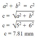
Equation 3
This means that the inner radius of the sprocket needed to be at least 8 mm if not more in order to clear the gearbox. Additionally, the sprocket needed to be thick enough to withstand stress without fracturing or warping. The final constraint on the sprocket was that the outer radius of the sprocket needed to conform to the Tamiya tread to ensure that there would be a whole number of teeth, and that they would be spaced properly. The ratio of teeth to radius in mm was determined by measuring the Tamiya brand sprockets and counting their teeth to be one tooth per millimeter of radius. This meant that if the outer radius was not a whole number of millimeters, the circumference of the sprocket would not accommodate a whole number of teeth with the proper spacing. The final design for the sprocket was chosen to have an outer radius of 11 mm and an inner radius of 9 mm to ensure that there would be enough clearance around the gearbox, and that the sprocket would be thick enough to withstand the forces being applied to it.
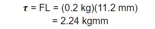
This meant that the effective torque arm radius was about 11.2 mm, because the total distance from the axis of rotation to the force being applied was the outer radius of the sprocket plus the height of the teeth of the sprocket. At this point, the projected mass of the robot was 200 grams. This meant that the robot’s motors together needed to produce:
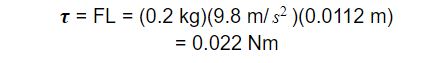
Equation 4
of torque. To confuse things, most motor manufacturers list the torque of their motors in kgmm. One kgmm describes the amount of torque required to lift a one kilogram mass with a lever arm of one millimeter. The unit relates mass to length instead of force to length, but assumes that the force acting on the mass is caused by gravity at earth’s surface. This means that force to mass conversions can be done easily by dividing by the acceleration of gravity: 9.8 m/s2. Recalculating the torque value in kgmm gives:
Equation 5
This means that the motors chosen for this project each need to produce at least 1.12 kgmm of torque in order for the E-racer to be able to climb the board. In order to meet this criterion, the low power, 210:1 gear ratio, Pololu micrometal gear motor was chosen. The datasheet for the motor claimed that it was capable of creating 1.12 kgmm of torque while drawing 62 mA, which was within the projected allotment of current capable of being supplied by the battery.
Also it should be noted that the formula used for torque in this post is a simplified version. Technically, torque is the cross product of the force and distance. This definition simplifies to the formula described above when the force applied is perpendicular to the length of the torque arm because the definition of the cross product gives:
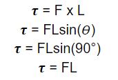
Equation 6
Additionally, this simplified formula makes the assumption that there is only one force acting on the sprocket which is applied tangent to the curve of the sprocket. In many cases, a force is distributed along an interval of distances from the axis of rotation. In these types of cases, it is necessary to use calculus to sum all of the torque by integrating the product the force as a function of distance by the corresponding distance. Symbolically this looks like:
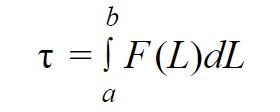
Equation 7
These definitions are not used in this post, but it is necessary to outline the scope of this document and when the methods used in it are applicable. If the force being applied is not perpendicular to the radial distance, the cross product definition should be used, and if the force is not applied at one distance, but a range of distances, the integral definition should be used.
Speed
In order to get the proper speed from a motor, it is important to supply it with enough power. This statement seems obvious, but it is important to understand the relationship between electrical power and mechanical power when choosing a motor and or battery. The simplified equation for the power of a motor is:
Equation 8
where P is power, I is current in amps, V is voltage in volts, ? is torque in newton meters, and ? is the angular velocity in radians per second. Obviously, this model is rudimentary as it neglects the energy lost in the conversion of electrical energy into mechanical energy, but it is useful for getting a quantitative estimate of how much torque and speed a motor will produce. In reality, the efficiency of most electric motors is 20-30%, which makes getting an accurate estimate difficult without testing or sophisticated simulation. A better way of estimating the performance of a motor is to use the data sheet provided by the manufacturer. The following diagram shows speed, current, efficiency, and power of a hypothetical motor as a function of torque.
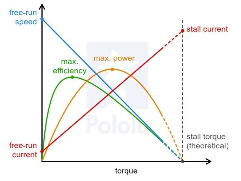
Figure 1. Power, efficiency, current, and speed as a function of torque
From observation, it is clear that the current scales proportionally to the torque, and the speed scales with a negative slope. What is less obvious is why the power is maximized in the middle of the graph. To explain this, it is necessary to take a look at a model of a motor as a circuit.
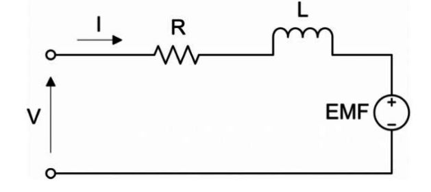
Figure 2. The circuit equivalent of a motor
The motor acts like a resistor, inductor and voltage source in series. The voltage source is called the back EMF of the motor and increases with the rotation speed of the motor. So for a fixed voltage, as the current increases, the speed decreases, and so does the back EMF. This means that as the current increases, the voltage across the EMF decreases, and the product of a line of positive slope and a line of negative slope produces a concave down parabola as shown in Figure 1. Specifically, the power consumed by multiplying the current by the voltage across the EMF defines the power input, and the speed multiplied by the torque defines the power output. The efficiency of the motor is then the power output over the power input. Because the voltage is constant, the power input scales linearly with the current, and therefore the efficiency can be defined by dividing the output power by the current and the supply voltage. Visually, the shape of the efficiency curve can be sketched by simply dividing the orange curve by the red line. This curve is helpful when choosing a motor, because the motor will perform the best if the load it drives is near the peak of the efficiency curve.
Method
The method used to test the torque of the motors involved using a luggage scale, a sprocket designed to fit the motor’s axle, and bit of nylon string strong enough to hold the expected tension. The motor was adhered to a table with tape and the sprocket was placed on the axle with the string tied around the circumference of the sprocket. The hook of the luggage scale was tied to the other end of the string, and the motor was then run and the tension force applied to the string was recorded with the scale. It is important to note that the motor should not be allowed to stall during this process; it should continue to rotate at a rate above 30 RPM at all times to avoid damage. Multiplying the force applied to the string by the radius of the sprocket gives the amount of torque generated.
A better method
A slightly better test would be to have the motor act as a winch and lift increasingly large masses. The torque could be calculated similarly to the method above, by multiplying the weight of the masses by the radius of the sprocket or reel and the RPM of the motor could be counted by hand or with a tachometer. Gathering the RPM as a function of torque and measuring the current with an ammeter would provide enough information to create a graph similar to the one in Figure 1, which should be more than enough to know how a motor will behave when operating.
Conclusion
This post is meant to outline the theoretical underpinnings of how torque is defined, how the definition of torque can be used to find how much force a motor will apply, and how the performance of a motor can be calculated using its data sheet.
References/Resources
- http://hyperphysics.phy-astr.gsu.edu/hbase/mi.html#rlin
- https://www.pololu.com/product/1443/faqs