Fall 2018 AT-ST Breadboarding using Frizting
Author/s: Patrick Nguyen
Introduction
The purpose of breadboarding is to make sure that the general wire layout is ready for when testings of the PID controls on our 2 dc motors are ready. Along with the motors are the shaft encoders to help control the speed and phase of them. The purpose of this test is to make sure that the PID control actually knows when the gears have made a full rotation and that they are both 180 degrees out of phase, so two phototransistors that will read reflective tape were implemented. One professional way of presenting the breadboarding is by using the program Fritzing, which is available for download off the internet.
Wiring Layout
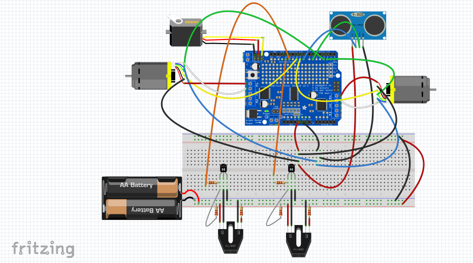
Figure 1: Fritzing Layout
One assumption that is not visualized on the image above is that the motor drive will lay on top of the Arduino. The 2 dc motors have shaft encoders already on them and they each contain the following pin outs: 1. Motor + 2. Encoder + 3. Encoder Phase A 4. Encoder Phase B 5. Encoder GND 6. Motor -. The red wire is pin out 1 and the white wire is pin out 6. The motor shield will be powered by the 5 volts coming from the Arduino. The 2 motor pins will connect to M1 and M2 on the motor shield respectively. The shaft encoder will also be powered by the 5 volt of the Arduino, so to have multiple pins receive the voltage, we will back tie wires with solder to have the respective pins act as 5V and ground. The phases of the encoders will go into pin 2 and 3 of the Arduino for PID control.
Motor Pin Out
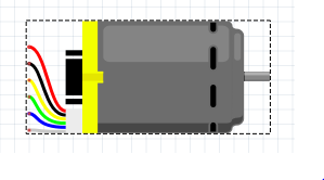
The motor we incorporated into our design is a six pin out where two are for the motor and four for the encoder. The following pin outs correspond to the following colors.
| White | Motor + |
| Blue | Encoder + |
| Green | Encoder Phase A |
| Yellow | Encoder Phase B |
| Black | Encoder – |
| Red | Motor – |
We need the encoder Phase A to go to our digital pin 2 and 3 so our Arduino code can use those as inputs. Encoder Phase B can go to any digital pin that are not occupied or named within the Arduino code.
Photo Sensor

The phototransistor used here is to send an interrupt pin to tell the PID control when we made a full rotation. We are trying to make these phototransistors act as absolute encoders so that our actual PID control knows when a full rotation of the gear has been done. We will place reflective material on the gear itself and place the photo transistor in front to recognize when the two gears are making full rotations.
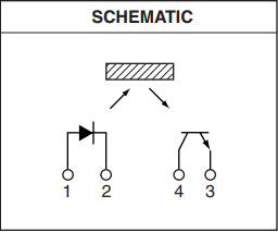
Figure 4: Pin Out of Photo Transistor
Pin 1 and Pin 4 are receiving voltage from our source while pin 2 will go to ground. Pin 3 will be sending a signal to act as our interrupt pulse to tell the PID control when a full rotation has ben made.
Conclusion
Considering that the 2 dc motors with shaft encoders are used along with the version 2.3 motor shield, wires needed to be soldered in the back to obtain multiple pin inputs act as 5 volts and GND. This breadboarding is only to implement the test of the PID control and not an actual representation of the final design. There was no use of the servo or the ultra sonic sensor in the design of the PID control.