IloMilo/Spring 2020
Metal Detection using the TI LDC0851
Author: Toby Johnson
Introduction
For our project, IloMilo, our robot will be autonomously navigating around obstacles to find another robot using a Time of Flight sensor. Though the obstacle avoidance will be done with this ToF, the robot still needs to stay on a straight path and make 90 degree turns. Because of this requirement some sort of line following device is needed to ensure that our robot can correctly navigate to obstacles and move around them . The line detection should also be contactless so as to reduce drag and strain on the robot’s motors. These requirements lead to choosing metal detection as it is ideal for sensing applications without contact.
A previous metal detector was designed for a line following robot; however, it did not perform extremely well. The sensing range was rather small and the results were less than ideal. To improve on this design then, a new metal detecting shield was designed with the TI LDC0851 Chip, as this integrated circuit was designed precisely for small distance, contactless metal detection and was well documented with similar applications.
Inductance to Digital Conversion (LDC) Background
A basic metal detector, like one might use to find valuable metals at the beach, senses metal via Eddy Currents. Eddy Currents are loops of current induced within conductors by changes in magnetic field1. A simple application of this is a coil inductor which stores up current and produces a magnetic field. When another conductive material is introduced to the magnetic field of the inductor (right hand rule) the magnetic field increases causing increased induction of the Eddy Current. This enables metal detection. The figure below shows how Eddy Current is induced when a conductive material is introduced to the magnetic field of two inductors.
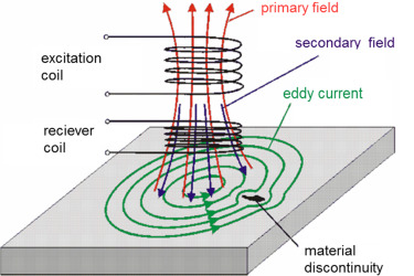
Figure 1: Eddy Current
After the object is introduced to the coil field, the induced current must be read to show that there is conductive material in close proximity to the coils.
Basic LDC Circuit Concept
The figure below shows a basic concept of an LDC circuit.
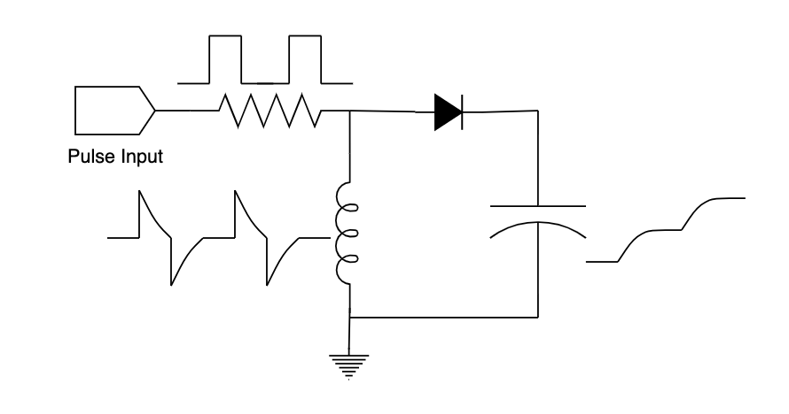
Figure 2: Basic LDC Circuit
The induced voltage is read across the capacitor and should continue to step up, as shown in the diagram above, when a conductive material is introduced to the inductor, within the sensing range.
The previous shield design for metal detection used this circuit with a PFET in enhancement mode after the input to increase input current. This design worked for a previous line follower, but with less than ideal results. This lead to looking for a better solution and ultimately to design a new shield using the TI LDC0851 integrated circuit.
Texas Instruments LDC0851 Overview
The LDC0851 chip by TI is an inductive switch, ideally designed for close range, contactless metal detection4. “It utilizes a sensing coil and a reference coil to determine the relative inductance in a system. The push/pull output (OUT) switches low when the sense inductance drops below the reference and returns high when the reference inductance is higher than the sense inductance.”4 This makes it perfect for our robot these applications fit our design requirements exactly. Here is a block diagram from TI for our application of the LDC0851
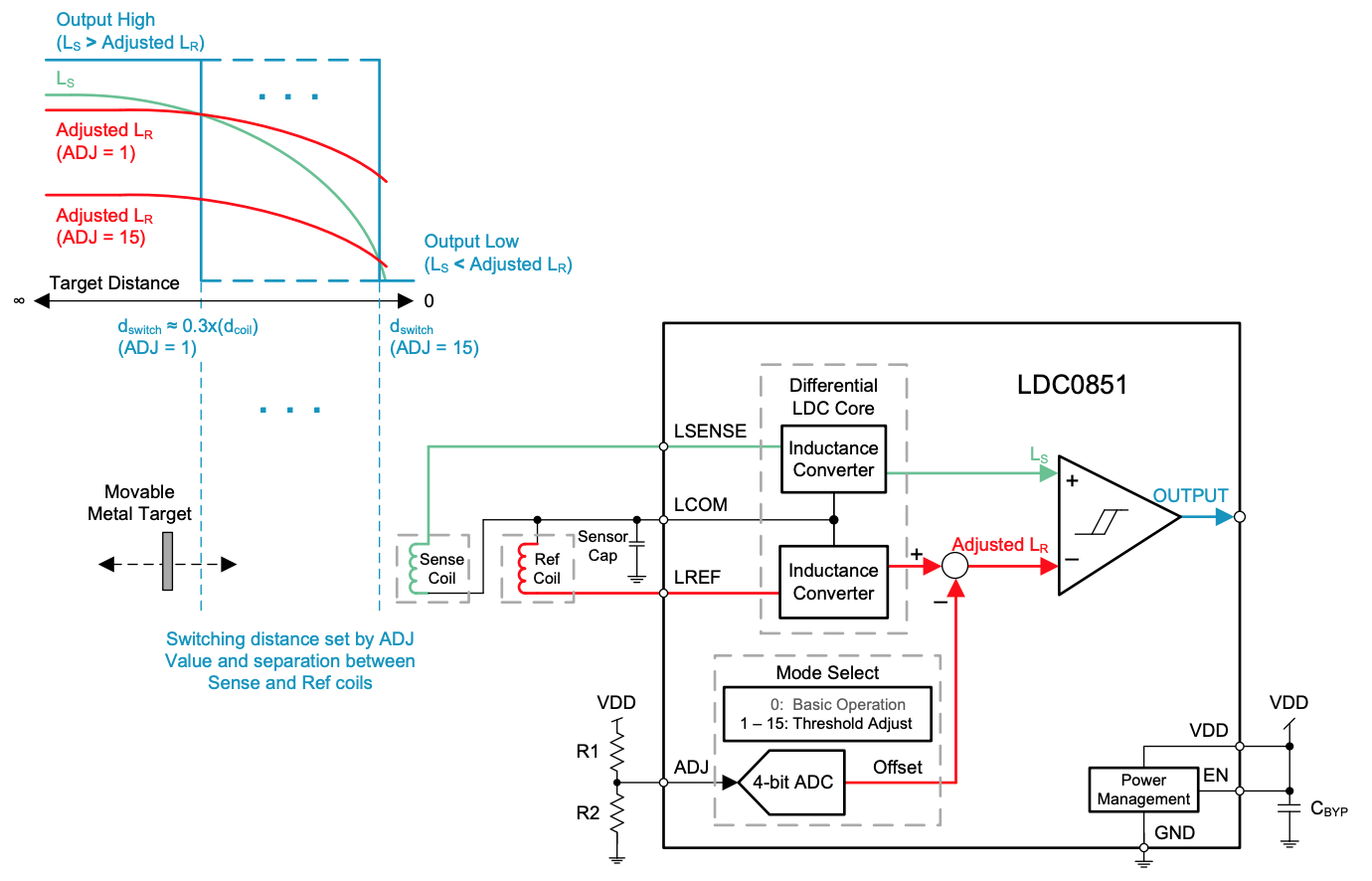
Figure 3: LDC0851 Sensing Application Block Diagram
As seen in the diagram, the IC has a threshold adjust pin that a voltage divider can be applied to in order to adjust the max distance detected. For our application however, since the distance between the conductive material and the sense coil will be constant, the ADJ pin was tied to ground to allow the greatest sense distance possible.
Designing Coils with the LDC0851
The use of stacked coils was also ideal for our application as the coils would have to be relatively small in order to fit under our robot. With inductive coils, generally increasing the outer diameter of the coil is the greatest factor in increasing the inductance. Because of our design constraints, we could only make the coils so big and therefore needed to use stacked, 4 layer coils to increase our inductance.
Below are the basic requirements for designing 4 layer PCB stacked inductance coils
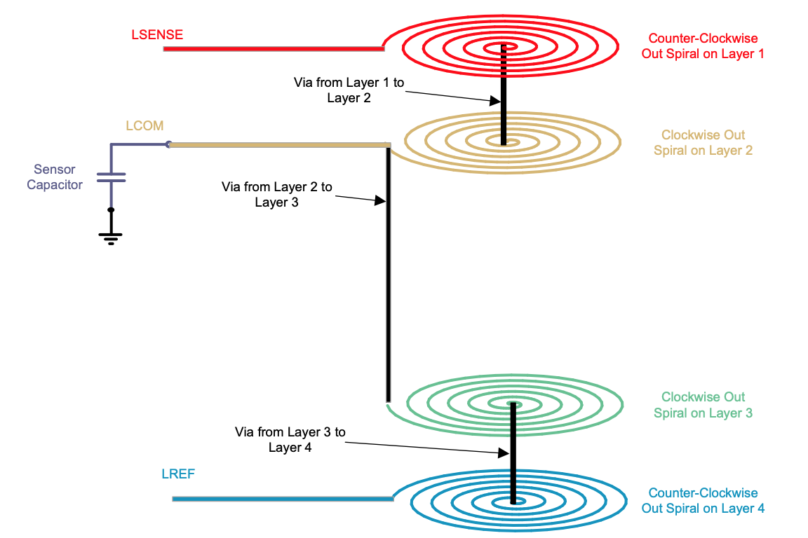
Figure 4: 4 Layer PCB coil basic design parameters
For our shield design, the sense (LSENSE) and reference (LREF) coils were switched to have the sense coil on the bottom and the reference coil on top as we want to detect metal beneath the coils.
Detailed design equations for the parameters of the coils can be found here; however TI has a webench tool for designing coils specifically for the LDC0851 chip: https://webench.ti.com/wb5/LDC/#/spirals. This tool generates a 4 layer PCB coil for an Eagle BRD file.
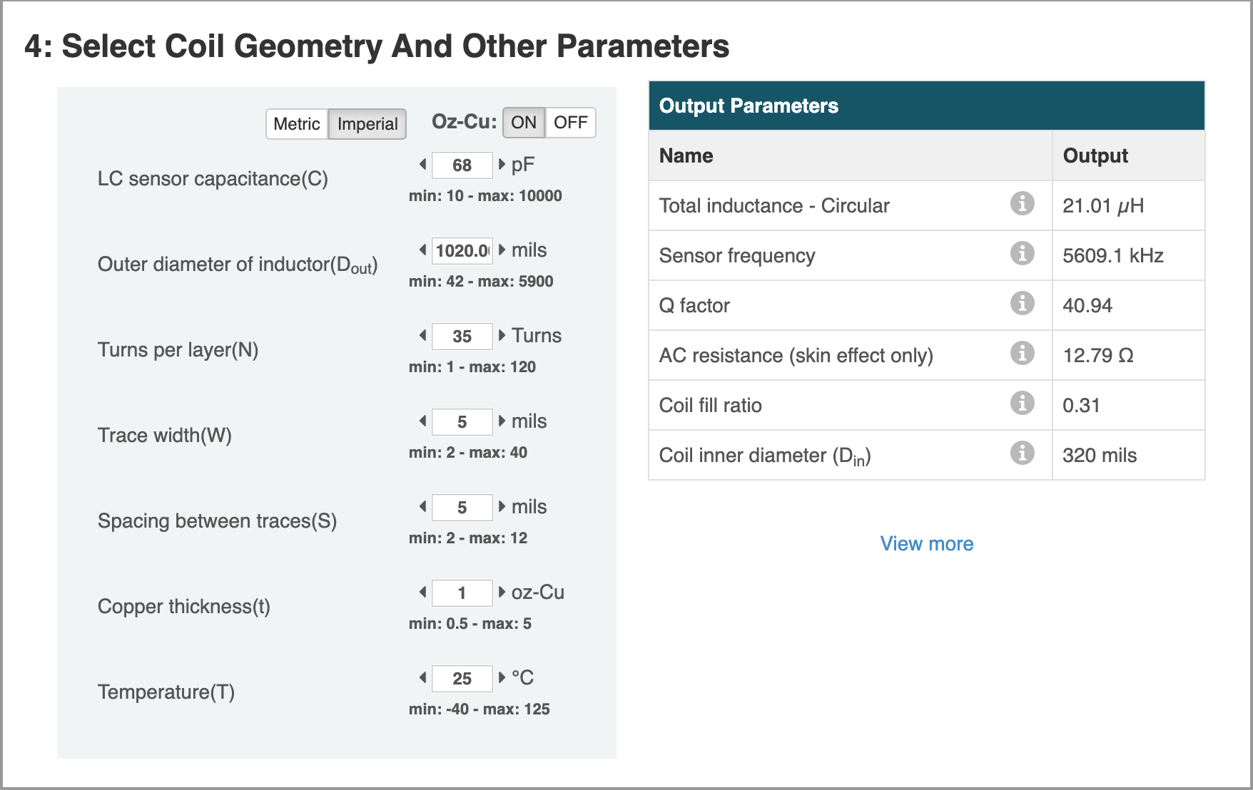
Figure 5: TI Coil Designer Tool
**Issues
When I designed my PCB I was unable to add the BRD file generated by the webench tool into my shield design. I was also not able to add the script for the PCB board file into my shield design. Because of this I was forced to look elsewhere for the coil designs to use in my actual PCB design in Eagle. Although the design process I ended up going through was a bit more tedious than simply generating the design with the webench tool, it was still much simpler than drawing the coils by hand.
Designing the PCB
Because of the issues with the webench tool for the coil design, I looked for a different solution and ended up using a ULP (User Language Program) in Eagle. Here is the ULP I used to create the coils for the PCB in Eagle: Coils ULP. This ULP allows user input for several coil parameters include trace thickness, space between traces, and number of turns. To design the coils for the desired inductance, I then input the data from the webench tool. I also made sure that the coils turned in the proper direction according to the TI LDC0851 datasheet.
The final shield design schematic and board are shown below
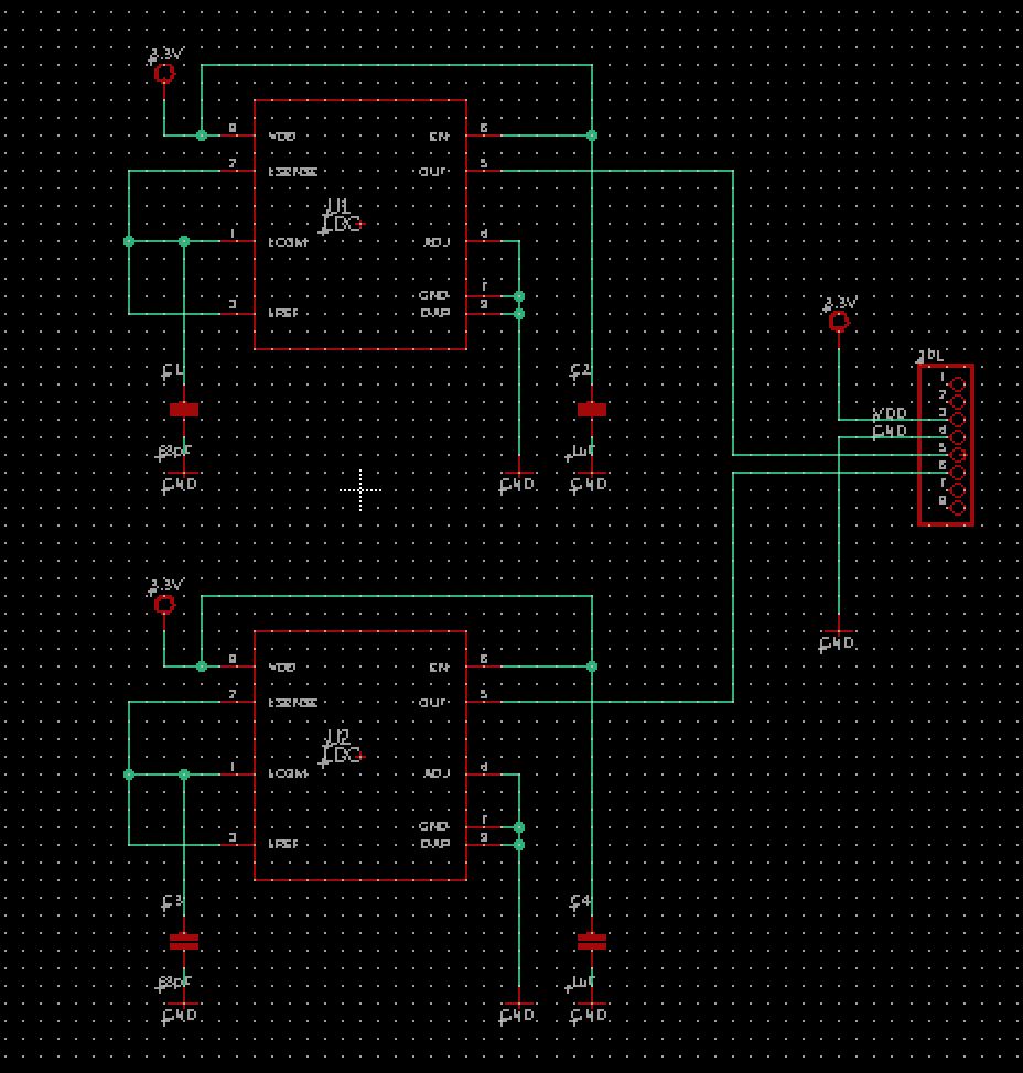
LDC Shield Schematic
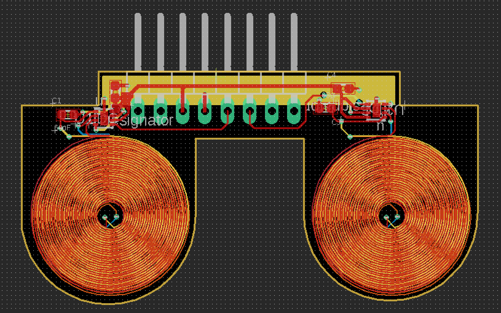
LDC Shield Board Layout
Conclusion/Final Notes
Designing the metal detecting shield utilizing the TI LDC0851 made the design much simpler as it only required 2 capacitors in addition to each IC. TI’s thorough documentation on the chip and design parameters also simplified the design process drastically.
One final note for designing the coils especially is the importance of width of the coil traces and the width between each coil trace. Before sending a PCB out for fabrication, always make sure you are using the proper design rules for the company you are having manufacture your board. You should also additionally check with the company directly to obtain more specific design rules. When I designed the coils, I originally did not have enough space between the coil traces, however, the design rules I was using did not see it as an issue. This unfortunately made the first fabrication bad (we ordered through OshPark) and I had to change this flaw. Luckily, I simply had to decrease the trace width of the coils by 1 mil to have enough clearance between each trace and this also increased the inductance of each stacked coil by about 25%.
References/Resources
- https://en.wikipedia.org/wiki/Eddy_current
- Figure 1:https://www.sciencedirect.com/topics/engineering/high-frequency-eddy-current
- Figure 2: https://www.instructables.com/id/Simple-Arduino-Metal-Detector/
- https://www.ti.com/lit/ds/symlink/ldc0851.pdf?&ts=1588962815574
- Figure 3: //www.ti.com/lit/ds/symlink/ldc0851.pdf?&ts=1588962815574
- Figure 4: //www.ti.com/lit/ds/symlink/ldc0851.pdf?&ts=1588962815574
- Figure 5: https://webench.ti.com/wb5/LDC/#/spirals
Resources: