Spring 2016 Pathfinder: Project Tango – Interactive Visualization of data from Tango using Paraview

2


By:

Tuong Vu (E&C – Sensors, Actuators and Power)

Peiyuan Xu (Project Manager)

Table of Contents

Introduction:

Google tango tablet can perform depth perception by using point cloud app, however, the  source code of  point cloud app is written in Java with different  modules. This  blog post assumed the reader has no experience in Java  programming, yet they can still extract data out from point cloud app. Paraview is an program on PC that offers alternate method to manipulate point cloud data, while the other method would involve  changing the Google tango Source code.

Paraview and VTK:

Paraview is a program run on the foundation of C, python,  and Java language. Paraview  version 4.01 was  design  for google tango  project. VTK (Visualization Toolkit) is used  to create digital filter in order to exclude any  unnecessary point  cloud data gather by Paraview.

For reference of how to set up Paraview on both PC and Tango tablet, see here

Testing Results:

Screenshot_2016-05-02-00-03-16

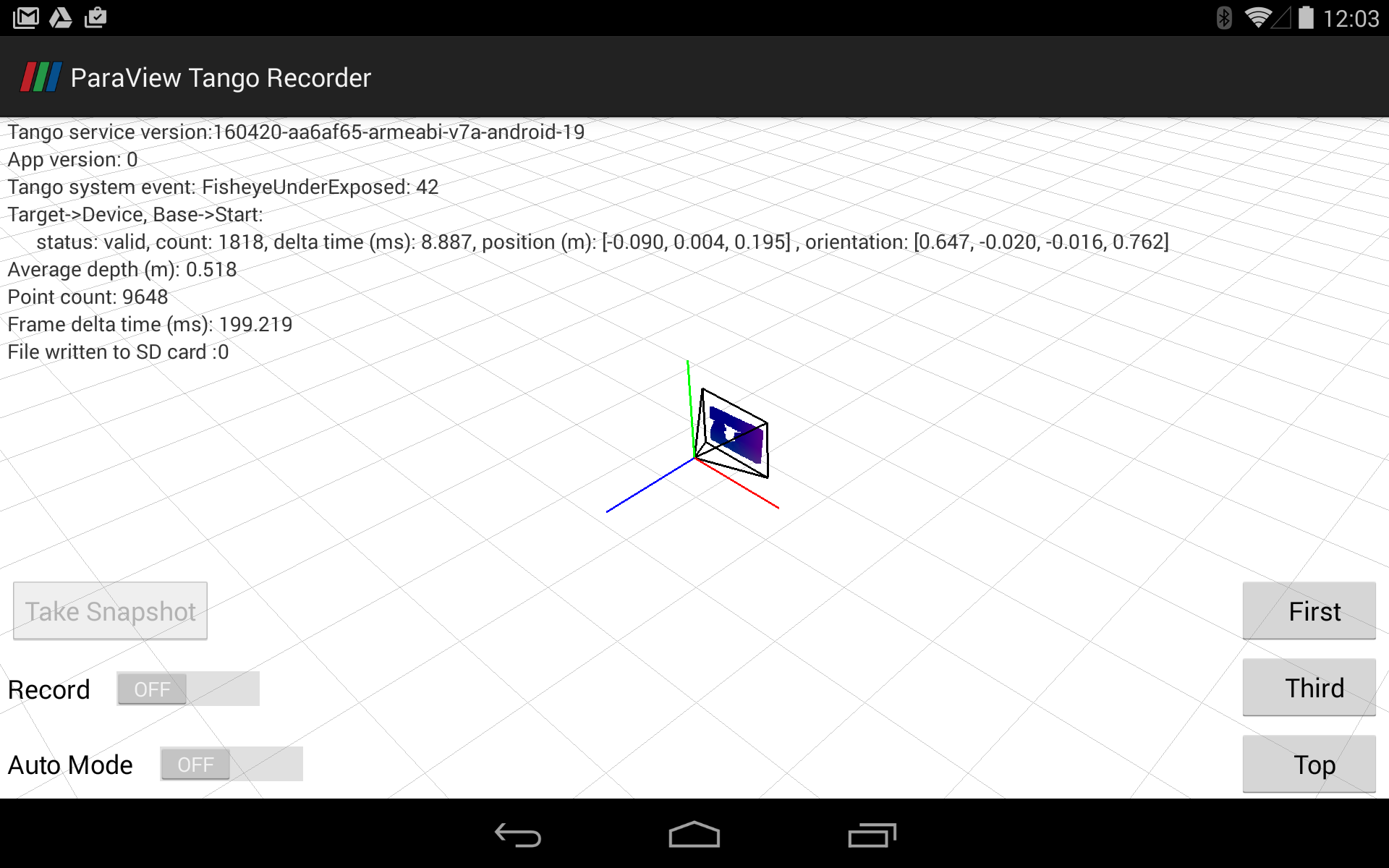
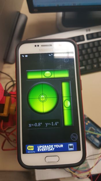
The above picture is a screenshot of Paraview Tango Recorder App. On the left side, There is a scroll button “record” that can be turned on and start recording the point cloud image.

Screenshot_2016-05-02-00-05-21

Then turn on the “Auto Mode” button, it will start scanning the area and capturing point cloud images. The “Take Snapshot” button will only take one image.


Screenshot_2016-05-02-00-05-43

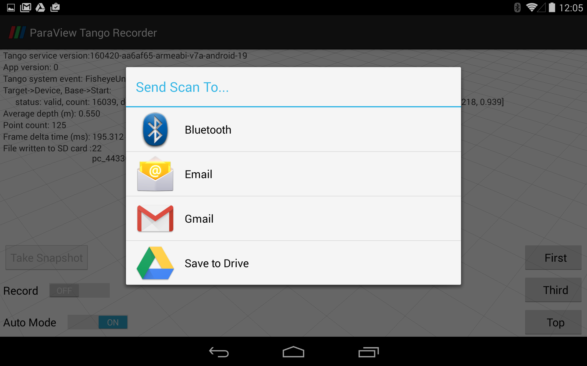
Once the “Record” button turned off, the app will save the files in VTK format and send them via Bluetooth or through Wi-Fi to emails or Google Drive. In order to process the data on PC, we choose to save to Google Drive and then import the files to Paraview program.

1

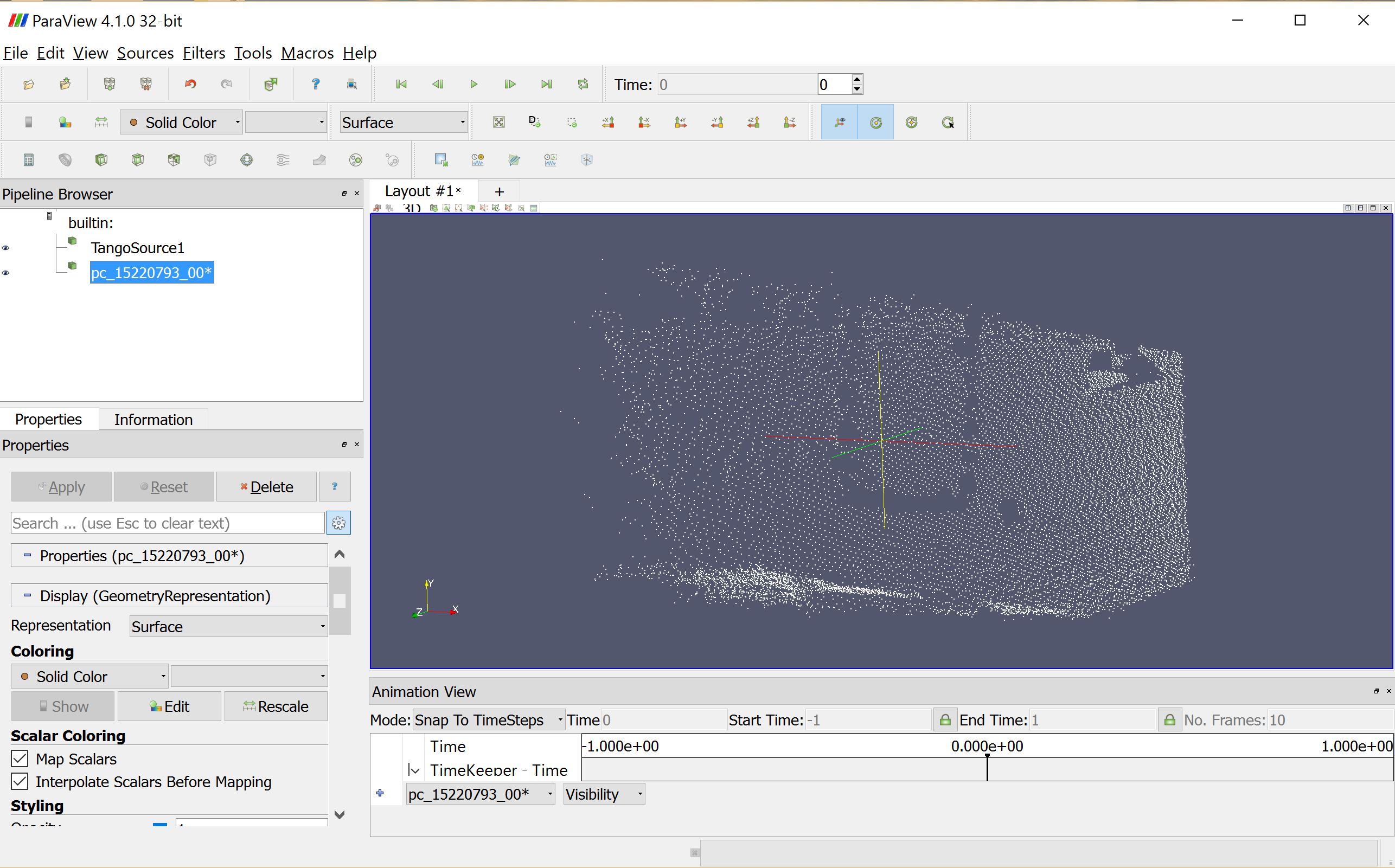
In the Paraview program, you can 3D view the point cloud data. if you record the data in “Auto Mode”. you can enable the animation view and see the video. Paraview has some build in filter that you can use to filter out the point cloud data, however, most of the filter applications are designed for 3D indoor mappings. Next step for us is to research into VTK library and learn to build our custom filter to filter out the irrelevant data and only leaves a single point or an area that we are interested.

Task for future semester

 After paraview and VTK  filter all  points, the specific point needed to be transferred to  Arxterra  app.  Arxterra app will use the depth information from point cloud to drive pathfinder.

VTK example code :

#include <vtkSphereSource.h>
#include <vtkPolyData.h>
#include <vtkSmartPointer.h>
#include <vtkPolyDataMapper.h>
#include <vtkActor.h>
#include <vtkRenderWindow.h>
#include <vtkRenderer.h>
#include <vtkRenderWindowInteractor.h>

int main(int, char *[])
{
 // Create a sphere
 vtkSmartPointer<vtkSphereSource> sphereSource =
   vtkSmartPointer<vtkSphereSource>::New();
 sphereSource->SetCenter(0.0, 0.0, 0.0);
 sphereSource->SetRadius(5.0);

 vtkSmartPointer<vtkPolyDataMapper> mapper =
   vtkSmartPointer<vtkPolyDataMapper>::New();
 mapper->SetInputConnection(sphereSource->GetOutputPort());

 vtkSmartPointer<vtkActor> actor =
   vtkSmartPointer<vtkActor>::New();
 actor->SetMapper(mapper);

 vtkSmartPointer<vtkRenderer> renderer =
   vtkSmartPointer<vtkRenderer>::New();
 vtkSmartPointer<vtkRenderWindow> renderWindow =
   vtkSmartPointer<vtkRenderWindow>::New();
 renderWindow->AddRenderer(renderer);
 vtkSmartPointer<vtkRenderWindowInteractor> renderWindowInteractor =
   vtkSmartPointer<vtkRenderWindowInteractor>::New();
 renderWindowInteractor->SetRenderWindow(renderWindow);

 renderer->AddActor(actor);
 renderer->SetBackground(.3, .6, .3); // Background color green

 renderWindow->Render();
 renderWindowInteractor->Start();

 return EXIT_SUCCESS;
}

1

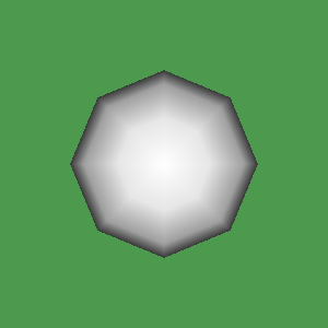
This  code  filters  the pixels  to make white  sphere and green background. The idea of this approach is trying to use the image processing and filtering method to get the point cloud data we want and on some level avoid Java Programming and modifying the point cloud app.

Source Materials:

  1. VTK example code:                                                                                              http://www.vtk.org/Wiki/VTK/Examples/Cxx/GeometricObjects/Sphere
  2. Paraview Setup:                                                                                                      https://blog.kitware.com/interactive-visualization-of-google-project-tango-data-with-paraview/
  3. Image:                                                                                                                                          http://ngcm.soton.ac.uk/blog/images/training/2015-06-24-VTK-logos.png


Spring 2016 Additional Fan Bracket Design

Posted by: Luis Valdivia (Project Manager)
Written by: Juan Mendez (Manufacturing Engineer)

Table of Contents:
Introduction
Design
Conclusion

Introduction:
Since weight became an issue with our vehicle, we had to think of an alternative solution to fix the yaw problem. Our alternative solution was to add an additional brushless fan to counter the yaw problem. In order to add on another fan we needed to find a way to mount it on to the current frame. We thought of drilling new holes on to the frame to add on to the bracket, but instead of making new holes, we decided to use the ones that were already on the frame. In order to put the fan between two of the ducted fans, I had to use the holes that were between two of the current metal brackets. I modeled the bracket to be 1.67 by .31 inches as shown in Figure 1 so that they can fit perfectly between two ducted fans.

Figure 1 Demonstrating dimensions of 5th fanbracket

5thfanbracket

Design:

I wanted to make sure that the bracket would enclose the bracket provided by the brushless fan so I made the bracket extend approximately 1.25 inches as shown in Figure 1.
After measuring the bracket that came with with brushless fan, we saw that it was 3.4 by 3.4 mm thick. This is equivalent to .13 inches. In order to make sure that the brushless fan bracket could fit into mine, I made the inner cut of .14 by .14 inches so it can slip in smoothly as shown in Figure 2A. In order to make sure that the 3D printer could print the part without having it warp, I had to make the outer dimensions be .33 by .34 inches thick as shown in Figure 2B. This allowed the part to be printed without any trouble.

Figure 2A and Figure 2B Demonstrating dimensions of bracket design

bracket design

Conclusion:

The result were the parts fabricated shown below in Figure 3 A & B. The brackets were able to mount on smoothly into the brushless fans with no problem. They were then easily mounted on between the ducted fans on the vehicle as seen in Figure 4. Additional brackets were fabricated incase we needed to add a 6th fan to fix the yaw problem.

Figure 3A and Figure 3B alternate angles of 3D printed brackets

printed piece

Figure 4 5th fan attached to 3D printed bracket

attached

Spring 2016 RoFi: PCB Layout

Christopher Andelin (Project Manager)

Mario Ramirez (Systems Engineer)

Qui Du (Manufacturing Engineer)

Andrew Laqui (Electronics and Controls Engineer)

Henry Ruff (Electronics and Controls Engineer)

Table of Contents

PCB Layout

Qui Du (Manufacturing Engineer)


Once I received the PCB schematic from the Electronics and Controls Engineers, I create the PCB layout.

First, I clicked on the Generate/Switch to board  button button at the top left corner of the schematic window. Then I clicked Yes on the Warning window to confirm that we will create a PCB layout from the schematic. The below window will appear:

figure 2

Figure 1: Generate/Switch to Board


Adjust PCB Board Size

I designed the PCB board the same size as the Arduino Mega (101.6 X 53.33mm) to allow the user to interchange the PCB with the Arduino Mega in RoFi’s head. To adjust the PCB board size, first I turned grid on by clicking the Grid button → changing the Unit to mm → selecting On at Display → and then by clicking Ok. Then I clicked on the top right corner of the white rectangular and adjusted the until shape until it reached 101.6mm X 53.33mm.

figure 2

Figure 2: Turn on Grid Display and change unit length

figure 3

Figure 3: Adjust the size of PCB board


Visualize and Understand PCB Design

figure 4

Figure 4: System Block Diagram with Arduino Mega

Since our level one requirement requires that we not use the Arduino Mega; we installed the ATmega1280 chip onto our PCB board. We still need to adjust the pin mapping from the ATmega2560 board to the ATmega1280 chip on the system block diagram. More information can be found at, https://www.arduino.cc/en/Hacking/PinMapping2560.


Component placement

The power trace takes up a lot of space on our PCB, therefore, it is better to isolate the power supply with other components.  In my design, I placed the power trace on the top border of the PCB board.

I began placing the ATmega chip, Bluetooth, USB chip, Accelerometer/Gyroscope onto the board and placed all the supporting components around them. Then I used smash features to smash and delete unimportant names on the PCB layout.

figure 5

Figure 5: PCB Component Placement


Make a Ground Plane and Copper Pours

Apply polygon on top layer.

figure 6

Figure 6: Draw Polygon on Top Layer

Next click the Ratsnest button to view the ground plane.

figure 7

Figure 7: Top Layer Ratsnest Results

Apply Polygon in bottom layer.

figure 8

Figure 8: Polygon Applied to Bottom Layer

Click Ratsnest button.

figure 9

Figure 9: Bottom Layer Ratsnest Results


Draw a Wire Signal

Determine a current width trace

According to our power report found here, https://www.arxterra.com/spring-2016-rofi-preliminary-project-plan/ each servo can draw up to 1.896A.

figure 10

Figure 10: Current Draw

Since we plan to order our PCB board from www.4pcb.com, I used the trace width calculator from their website to determine the trace width of each wire.

Note: The thickness of the trace cannot be adjusted in Eagle CAD. We can order the trace thickness when we send the PCB layout to the PCB fabrication house. In our PCB layout, we ordered a 2 oz/ft^2 thickness.

figure 11

Figure 11: Required Trace Width

figure 12

Figure 12: Visual of Current Trace Width


DRC Check

Each PCB fabrication house has its own set of design rules, since we are using www.4pcb.com to fabricate our PCB, we followed their design rules.

4pcb Fabrication House DRC Check

Step 1

Download the DRC file by going to,  http://colinkarpfinger.com/blog/2010/ordering-pcbs-designed-with-eagle/.

Right click typical_4pcb.dru → choose Save link as → Save the file

figure 13

Figure 13: Right Click typical_4pcb.dru

Step 2

The window below appears once the DRC check icon is selected in the board window.

figure 14

Figure 14: DRC Window

figure 15

Figure 15: No DRC Error in our PCB Layout


Create Gerber Files

Step 1

Enable vector front by going to Option → User Interface → check Always vector front → OK

figure 16

Figure 16: Enable Vector Front

figure 17

Figure 18: Select CAM Processor

Open the CAM job → choose the CAM job file → click Open → click Process Job to generate Gerber files.


Get PCB Layout Quote From Fabrication House

After I zipped all the Gerber files and uploaded them to, www.4pcb.com, I received the PCB Layout Quote.

figure 18

Figure 19: PCB Layout Quote from www.4pcb.com


Spring 2016 re-design of structure rods

Posted by: Luis Valdivia (Project Manager)
Written by: Juan Mendez (Manufacturing Engineer)

Table of contents
Introduction
Approach
Re-design

Introduction

Space and weight was an issue with the vehicle. Since we were going to add a buck converter to control the brushless fans we had to reduce the weight of our current vehicle in order to compensate for the weight added on by the brushless fans and buck converter. We also noticed, some of the rod ends were broken from over tightening the set screws to the brackets (from previous semesters). Figure below demonstrates the damaged rods. 

Figure 1.1 Demonstration of damaged Carbon Fiber rods

20160501_135111

Approach

To reduce the weight, I redesigned the rods that were hold the ducted fans together and made them smaller in length. There were three rods that held the fans together, One of which was 6 inches long and the other two were 2.75 inches long. This was a simple modification. I made the rods to be .46 inches in diameter which was the same size as the previous rods. Since we wanted the rods to be shorter, I made them 1.7 inches long. By doing so, we were able to get rid of the long rod and have four individual rods for each ducted fan. We were able to reduce the weight from 5 grams to 3 grams. 

Re-design

Figure 1.2 Design of rod next to 3d print of rod

rodcomparison

Figure 1.3 New position of battery due to 3d printed rod

We were also able to remove the middle part of the frame which gave us more space to work with. Now we have no worries about the battery hitting the floor or any surface that the vehicle is resting on.

batterycomparison

Spring 2016 Trade off study: 5 Blade EDF vs 10 Blade EDF

Written by: Luis Valdivia (Project Manager)
Posted by: Luis Valdivia (Project Manager)

Table of contents
Introduction
Results
Conclusion


Introduction:
Due to weight concerns, the spring 2016 UFO Ab-ducted group was advised [by the instructor] to perform trade off studies between 5 blade Electric Ducted Fans (EDFs) and 10 blade Electric Ducted Fans (EDFs). This study will give our group and understanding the benefit of either configuration. Ideally, the 5 blade fans would be lighter than the 10 blade fans. If we are able to deliver the same amount of thrust with a lighter fan, our vehicle would be able to achieve liftoff with the same sized EDFs.


Results:
Weighing both EDFs, we measured the 5 blade EDF at 93g and the 10 blade EDF at 100g.

Figure 1.1 Weight of 5 blade EDF (in grams)

5bladeweight

Figure 1.2  Weight of 10 blade EDF (in grams)

10bladeweight

Table 1.1 results from different thrust values for 5 blades edfs and 10 blade edfs

Throttle 5 blade EDF (g) 10 blade EDF (g) Allowed weight of vehicle with 5 blades in (g) Allowed weight of vehicle with 5 blades in (g)
off 0 0 0 0
min 7 7 14 14
mid 140 235 280 470
max 530 650 1060 1300

Figure 1.3 Throttle position at minimum (after multiwii has been armed)

zerothrust

Figure 1.4 Throttle position at middle

midthrust

Figure 1.5 Throttle position at maximum

fullthrottle

Conclusion:

Measuring the thrust with the setup in figure 1.6 and figure 1.7 , we concluded the 10 blade fans produced more thrust with no significant change in weight or size to the 5 blade competitors. For our application, it seems like the 10 blade fans will bring in slightly more weight that won’t contribute to much since they produce almost twice the amount of thrust the the 5 blade fans.

Figure 1.6  Set up used to measure thrust (in grams) of 5 blades

5bladethrustweight

Figure 1.7 Set up used to measure thrust (in grams) of 10 blades

10bladethrustweight

Spring 2016 RoFi: Bluetooth Verification Test

Christopher Andelin (Project Manager)

Mario Ramirez (Systems Engineer)

Qui Du (Manufacturing Engineer)

Andrew Laqui (Electronics and Controls Engineer)

Henry Ruff (Electronics and Controls Engineer)

Bluetooth Verification Test

Mario Ramirez (Systems Engineer)

Test Objective

To verify that a Bluetooth module, HC-06 and a cell phone are able to communicate within a distance of 10 feet +/- 0.5 feet.

Tools

Figure 1 indicates that a measuring tape is needed to verify this test.

figure 1

Figure 1: Measuring Tape

Preliminary Info

Bluetooth code: https://drive.google.com/drive/my-drive

Bluetooth Circuit

Figure 2 shows how to connect the Bluetooth to the Arduino for this test.

figure 2

Figure 2: Fritzing Diagram

Procedure

Setup the Bluetooth module, Arduino and a LED.  Verify that the code is uploaded to the Arduino and begin.

1.Lay the measuring tape and create a distance of 10 feet.

figure 3_compressed

Figure 3: Measure Distance

2. Starting at 1 foot away from LED, turn the LED on and off with your phone to insure you are connected.

3. Move away 0.5 feet and again turn the LED on and off to insure you are connected.

figure 4_compressed

Figure 4: Turn LED on and off while moving back

4. Repeat step 3 until you reach 10 feet.

figure 5_compressed

Figure 5: Turn LED on and off at 10 feet

Results

Figure 6 is a table of my results.

figure 6

Figure 6: Results

In our requirements the Bluetooth module must have a range of at least 10 feet; from our verification test, we have met this requirement.  Trial 4 was a test to verify our max range and 27 feet was the maximum range we could physically move away from the Bluetooth module while remaining in the same room.

Spring 2016 RoFi: Bluetooth Communication

Christopher Andelin (Project Manager)

Mario Ramirez (Systems Engineer)

Qui Du (Manufacturing Engineer)

Andrew Laqui (Electronics and Controls Engineer)

Henry Ruff (Electronics and Controls Engineer)

Bluetooth Communication

Mario Ramirez (Systems Engineer)

To meet requirement 1.8, RoFi must communicate with the Arxrobot App and have an on and off state using the users phone.  Begin your Bluetooth connection by downloading the Arxrobot firmware, https://github.com/arxterra/BiPed-Robot.  This code has the commands and command decoder subroutine to control RoFi using the Arxrobot app.

First, connect and setup your Bluetooth mode, HC-06.  The pass code for connecting to the module with your phone is ‘0000’.

figure 1

Figure 1: Bluetooth Fritzing Diagram


figure 2

Figure 2: Bluetooth Fritzing Schematic

Within the Arxrobot firmware a custom command will be made.

figure 3

Figure 3: Arxrobot Custom Command

To initially test the custom command, a simple LED on and off command will be implemented within the command decoder subroutine.

figure 4

Figure 4: LED Subroutine

Once proper Bluetooth connection is tested, change the implemented command to your desired action.  For RoFi, we created a trigger after the command is received.

figure 5

Figure 5: Trigger Command

When the command packet is sent, the code will then read the 3rd byte.  If the byte is HIGH it will set trigger to HIGH.  If the byte is LOW it will set trigger to LOW.  Using this trigger variable, an “if” statement was implemented into our main loop code.

figure 6

Figure 6: HIGH or LOW Command

Figure 6 shows two “if” statements for different values of the trigger.  When the trigger is HIGH, it will light an LED and put RoFi into an Update Action subroutine which allows RoFi to update to its next frame.  When trigger is set to LOW, RoFi will not take any action and will remain at its current frame until trigger is set back to HIGH.

Spring 2016 RoFi: Calibration

Christopher Andelin (Project Manager)

Mario Ramirez (Systems Engineer)

Qui Du (Manufacturing Engineer)

Andrew Laqui (Electronics and Controls Engineer)

Henry Ruff (Electronics and Controls Engineer)

Calibration

Mario Ramirez (Systems Engineer)

Introduction

Before attempting to walk with RoFi, a calibration test must be done.  Using Robot Poser, Jonathan’s instructions and the calibration file (located below), perform the needed test and create your own calibration file.  This file will be RoFi’s starting/zero position for each routine in the future.  All future angles will be in reference to these zero frames.

Robot Poser:  http://www.projectbiped.com/prototypes/rofi/programs/robot-poser

This download includes the calibration file.

Jonathan Dowdall’s instructions: https://docs.google.com/document/d/1H0iGTlUO-VljwtqiN5W3QWxoLYYhNEEphhULrg87Wgc/edit

Blender File for RoFi calibration:

https://docs.google.com/file/d/0By_h1KTMNaWNcmlMS0FNWGJ5OVE/edit

This post is in reference to, https://www.arxterra.com/bipedal-robot-calibration/.

Our team’s calibration

Figure 1 shows RoFi in High Roll Position.

Figure 1: High Roll Position

Figure 2 shows that RoFi’s foot is level.

figure 2_compressed

Figure 2: Verifying Level Foot

Figure 3 shows RoFi’s leg is perpendicular to the table.

figure 3_compressed

Figure 3: Verifying Perpendicular Leg

Figure 4 shows RoFi in High Position.

figure 4_compressed

Figure 4: High Position


Spring 2016 Velociraptor: Updated Block Diagrams

By: Camilla Nelly Jensen (Systems Engineer)

According to the Critical Design Review Debrief, the team had made some error in the CDR powerpoint. These errors have been fixed and shown below.

For the System Design, the Active Control Circuit for the software blocks of the dynamic walk was missing and thus that circuit has been updated along with the rest of the system block diagrams for the Velociraptor in this blog post. Likewise, the interface matrix has been updated in order to show leftover available pins of the microcontroller.


blog post pic

 Figure 1: Updated System Block Diagram

The system block diagram displayed in figure 1 shows the interface connections of the inputs (Arxterra application) and outputs (servos) of the Velociraptor. For the updated version both sensors, ultrasonic and accelerometer and Bluetooth module have been mounted on the PCB along with the microcontroller, some directly into the pins of the microcontroller in order to minimize the use of wires to establish connections. Since microcontroller requires voltage input of 7-12 V, two batteries in series (3.7V*2=7.4V) have been placed on the head to provide that. The other two batteries have similarly been placed in series on the tail but as the servos require an input voltage of 6V the batteries have been connected to a voltage regulator to downsize the 7.4 V to match the 6V for the servos. The location of the batteries has been chosen to minimize the weight on the body of the robot.


Interface matrix Final

Figure 2: Interface matrix

Figure 2 shows the components of the Velociraptor’s pin connections and the leftover available pins on the Arduino Micro Atmega32U4 microcontroller board. The interface matrix hasn’t changed much from the PDR since we decided to go with the original components after testing other components. This comprises testing of the accelerometer where the first objective was to use the MPU-6050 3 Axis Gyro Accelerometer Sensor for the Velociraptor to detect an incline. But after testing the accuracy of the gyro-accelerometer is showed an error of 1-2° degrees and took up too much memory of the microcontroller and thus the group decided to go back to the original accelerometer ADXL335 that detected inclines more accurate and takes up less memory. Likewise, with an ultrasonic sensor the first intent was to utilize the HC-SR04 Ultrasonic Ranging Sensor but during tests, the sensor would loose signal and thus not valid to use for the Velociraptor to detect obstacles. Therefore, the group decided to change to the MB1030 LV-MaxSonar-EZ3 Ultrasonic Rangefinder, which operated to the accuracy listed in the datasheet and did not loose signal. The ultrasonic sensor is, therefore, the only component that has been changed for the setup and the LV-MaxSonar-EZ3 utilizes one pin less than the HC-SR04 only a TRIG pin.


Software block statical w_ legend

Figure 3: Active control circuit for statically walk

The software block diagram in figure 3 shows how the input command is sent via the Bluetooth module and through what pinouts to reach the Arduino firmware blocks to be decoded and handled before sent as subroutines to the output components, the servos to act the subroutines sent. The sensors, ultrasonic and accelerometer also gives inputs to the subroutines of the servos and thus if the ultrasonic sensor detects an obstacle the input routine shall block the MOVE subroutine for the servos. Likewise with the input from the accelerometer, if it detects an incline, an input routine will be sent to the servos subroutine and change the subroutine (walking code) in order to adjust to the incline.

For the Velociraptor, we are only sending commands from the Arxterra application to the servos to perform and not receiving any data from the components to the Arxterra application. The orange example box on the left shows how telemetry/data from the batteries could have been implemented and handled; the status of how much power the batteries have left could have been remotely sent back to the Arxterra application via the Bluetooth’s receive (RXD) channel in order to keep a real-time track of when to recharge the batteries.


Software block Dynamic w_legend

Figure 4: Active control circuit for Dynamic walk

Spring 2016 A-TeChToP Seizure Watch SAMB11 Bluetooth Connection

By Robin Yancey (Systems Engineer)

Introduction

In order to meet the communication requirements for the ATeChToP device, such as requirement 11 to use BLE v4.1 protocol, the flash memory had to be programmed to meet the services and characteristic properties of the HM-10 module that Arxterra was scanning for. The following PowerPoint presentation introduces the layers of the protocol and then focuses on the top control layers the GATT and GAP that must be used when programming the flash memory.

Read more