By Christine Vu (Missions, Systems, and Tests) and Henry Nguyen (Electronics and Control)
Purpose
This is a summary of all Arduino code modifications for the pick and place machine to work with our needs.
Modifications for Java can be found here.
Our files can be found here: https://github.com/cvuchristine/MakeblockPlotter.git
Required Arduino Code modifications
- Pinout Reassignment
- Z-Axis Arduino Code Modification
- The original Makeblock X-Y Plotter Robot Kit controls the Z-axis using a microservo and pen to control. However, we decided to use a stepper motor to control the Z-axis so it can be suspended on a threaded drive.
- Addition of A-Axis (rotation of IC Chips)
- This concept requires an addition of another stepper motor to be able to self-automate and correct the orientation of the IC Chip.
- Limiting Switch Feedback (notifies that we’ve gone too far)
- The addition of the limiting switch needed to be added to the Z-control here.
- Microservo control (reel feeders)
- The microservos will control the reel feeders’ cut-tape, which could help keep the cut-tape away from the vacuum nozzle.
- Solenoid Valve Control (vacuum suction)
- Solenoid valve will be able to close off the vacuum suction since the vacuum pump does not have its own controllable switch.
Updated Me UNO Shield
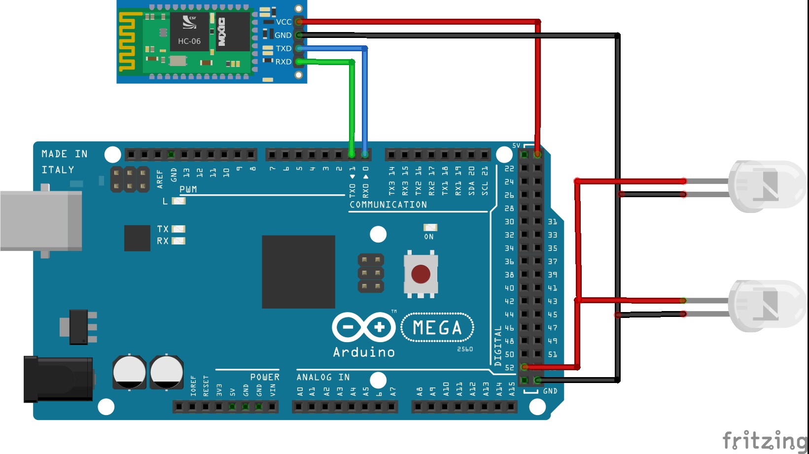
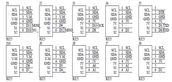
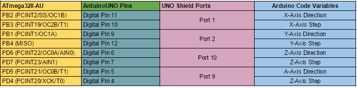
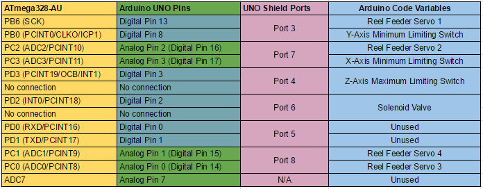
Using the Me UNO Shield, we were able to select the following ports as shown below. It is important to note that not all ports hold 2 digital I/O or analog pins. Port 5 was also unable to be used because it holds TX and RX pins, and our G-Code lines are sent serially.
The pinouts are shown below:
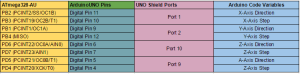
Figure 1. Stepper Motor Pinouts and Variables.

Figure 2. Limiting Switches and Reel Feeder Pinouts.
Code Processing
Makeblock is an open-source company and provided code for the X-Y Plotter Robot Kit.
URL: https://github.com/Makeblock-official/XY-Plotter-2.0/tree/master/software/GCodeParser
The Makeblock code was originally meant for 2 stepper motors (X-Axis and Y-Axis) and 1 microservo motor (Z-Axis) and two sets of minimum and maximum limiting switches, which was a safety factor used in case the motor moves the axes beyond the X-Y Plotter frame.
Summary of Makeblock X-Y Plotter Arduino Code
The Arduino code provided includes three Arduino files — GCodeParser.ino, process_string.ino, and stepper_control.ino.
GCodeParser.ino
This is the main loop to initiate pinouts and variables. The GCode interfaces with Java by receiving GCode serially line-by-line.
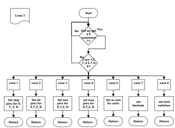
Process_string.ino
The line of G-Code sent through the serial monitor processed here. It search for specific lines such as $ and G-Code. The commands are placed in the table shown below. Often times, the G-Code is followed by a specific X-Y-Z-coordinate.
| Standard G’s |
Definition |
| G0 |
Nothing |
| G1 |
Move stepper motors at full speed |
| G2 |
Create clockwise arc |
| G3 |
Create counter-clockwise arc, declare values first, then calculates how many steps |
| G4 |
Delays GCode Commands using ‘P’ command (i.e. G4 P200 means delat 200 ms) |
| G20 |
Moves steps per inch |
| G21 |
Moves steps per mm |
| G28 |
Moves back to origin at full speed |
| G30 |
Moves back to origin based provided a certain coordinate at full speed |
| G90 |
Moves to coordinate at full speed |
| G91 |
Moves in increments |
| G92 |
Sets current position as origin |
| M |
Placed in the Arduino Code — Doesn’t mean anything in Arduino Code |
| ‘$’ Cases |
Definition |
| $1 |
Sets step pinouts |
| $2 |
Sets direction pinouts |
| $3 |
Sets limiting switch pinouts (for minimum) |
| $4 |
Sets limiting switch pinouts (for maxmimum) |
| $5 |
Enable Servo for Z-Axis **Removed for our purposes** |
| $6 |
Declares how many steps per mm should be moved |
| $7 |
Declares feedrate |
| Customized |
Definition |
| $9 |
Turn on solenoid valve |
| $10 |
Turn off solenoid valve |
| $11 |
Move microservo 1 |
| $12 |
Move microservo 2 |
| $13 |
Move microservo 3 |
| $14 |
Move microservo 4 |
Table 1. GCode Commands processed by Arduino.
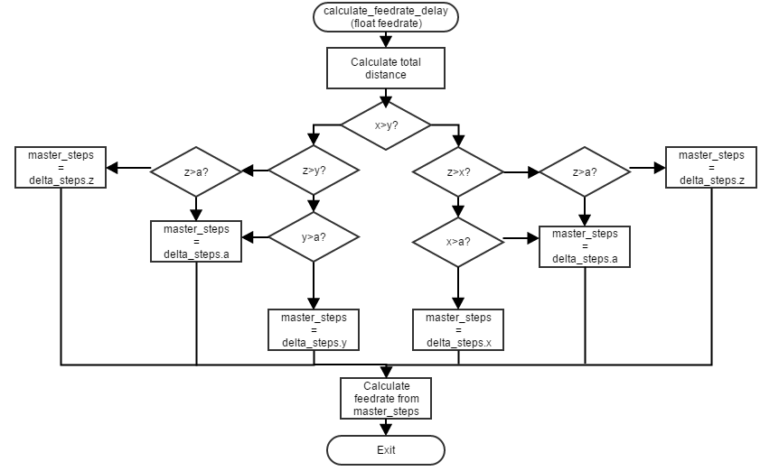
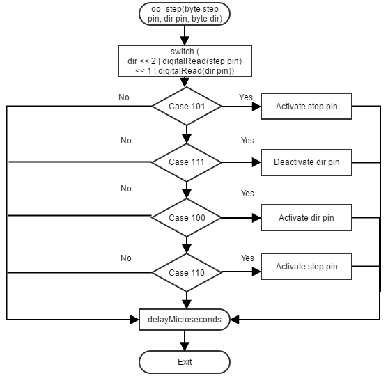
Stepper_control.ino
This file includes functions/subroutines called out by the process_string.ino file. It will calculate how much the motors should be moving.
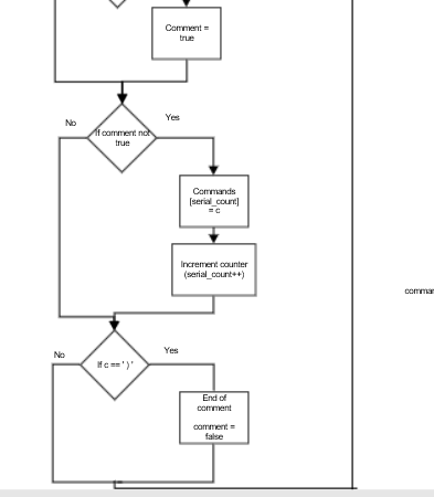
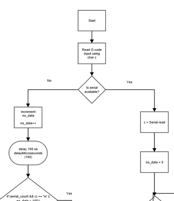
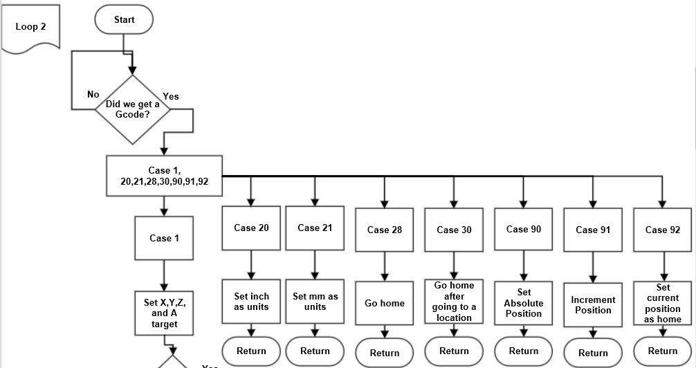
Flowcharts
Flowcharts were also made to help us understand the code and each purpose of the subroutines and functions in the file.
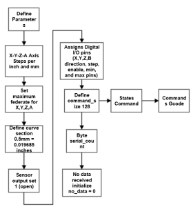
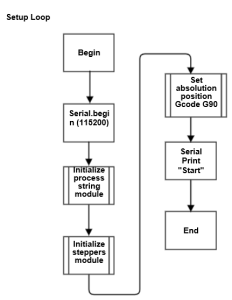
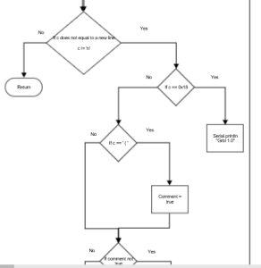

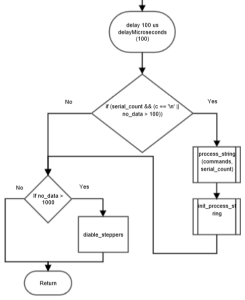

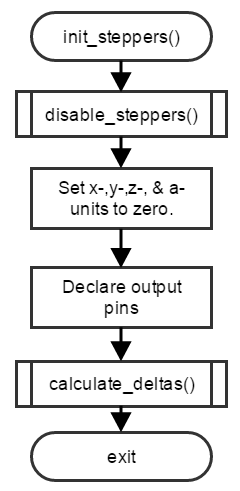
Figure 2a. GCodeParser.ino
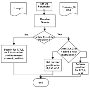


Figure 2b. process_string.ino
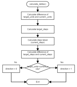
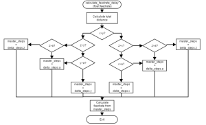
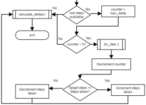
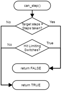


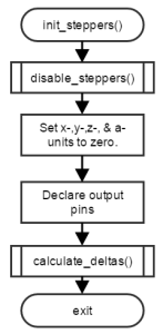
Figure 2c. stepper_control.ino
Pinout Reassignment
Blog post on the pinout reassignment can be found here: https://www.arxterra.com/spring-2016-3d-smd-me-uno-shield-and-software/
Z-Axis Code Modification
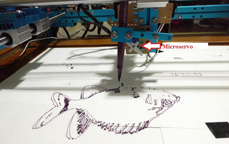
The Z-Axis was originally controlled by a microservo, which would tilt the pen up and down, as shown on Fig. 3. This was not sufficient to control our vacuum head, so we decided to work with stepper motors and remove the servo control in the code.
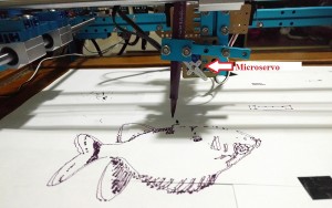
Figure 3. Original Z-Axis control with microservo.
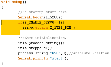
The original Arduino code included a servo pinout and write attachments.

Figure 4. Original Arduino Code setup section included the function servo.attach(), which was used to control the Z-Axis.
The function highlighted in Fig. 4 was commented out, since our stepper motor would not use this function. To remain consistent with the code, we decided to go through each line in the process_string.ino file to determine where the servo library functions are called out and remove them so we could switch to stepper motor control.


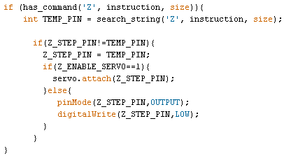
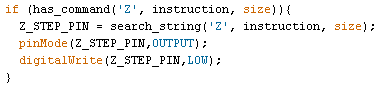
Figure 5. (Left) Original Arduino code. (Right) Modified Arduino Code for Case $1, which initiates the pinouts.
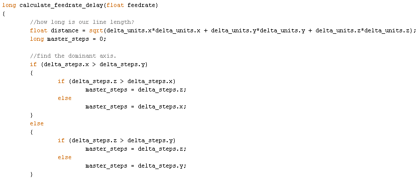
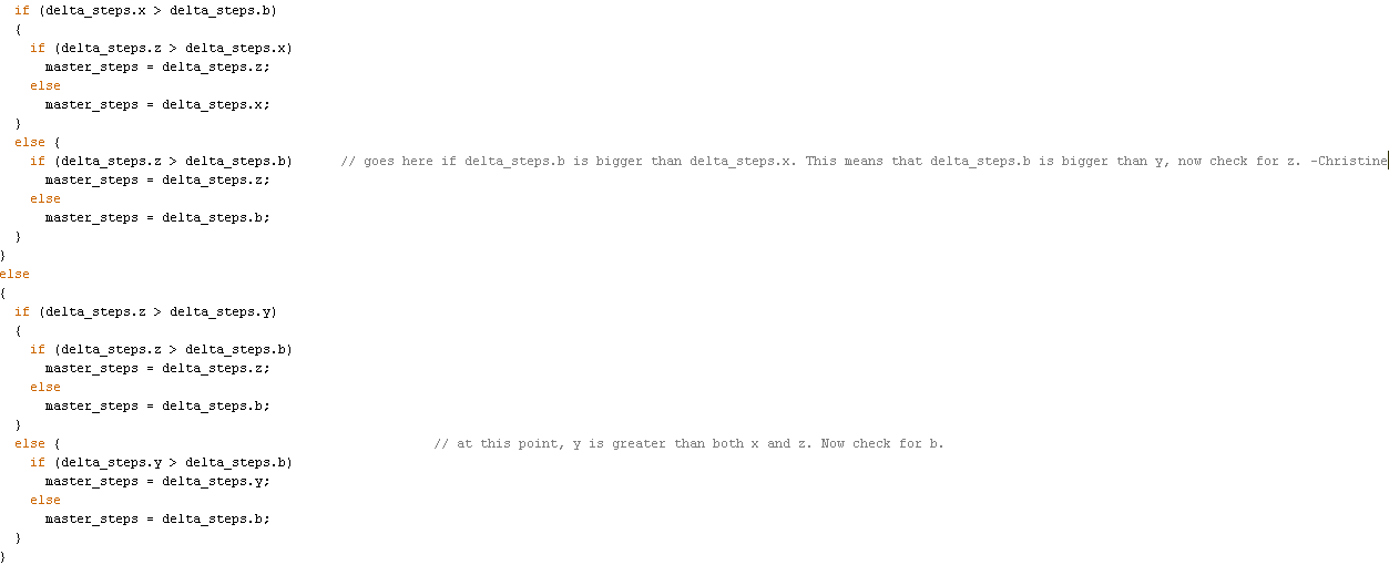
In the stepper_control.ino file, there was a function to determine which was the dominant axis to calculate the feedrate delay. Z-coordinates were originally not implemented, so we had to implement this portion.We also added the A-Axis at this point, which is labeled as the “b” variable.

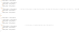
Figure 6. (Left) Original Arduino Code. (Right) Modified Arduino Code for both the Z-Axis and A-Axis code.
Addition of A-Axis
The A-axis is controlled by a stepper motor, so it was important to assure that each variable is declared each time the X-Axis and the Y-Axis are called out. Because we decided to utilize the stepper motors similar to the X-Axis and Y-Axis, the feedrates and the steps per mm were the same.
The changes to each call-out are shown below. We decided to use variable “b” because the Java code already uses the variable “a”, and the arduino code can read only one letter at a time.
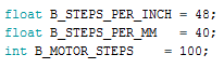
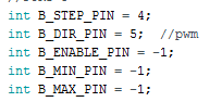

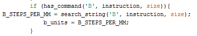
Figure 6a. Addition of A-axis using the variable ‘B’ in the GCodeParser.ino file.
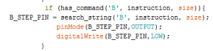

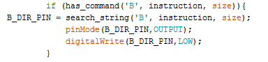
Figure 6b. Enables the step and directions pins for Me UNO Shield pinouts. This was modified in case ‘$1’.

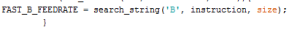
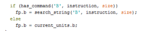
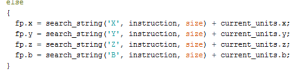
Figure 6c. Added lines to search for variables of ‘b’ so that motors are able to be moved. If a line ‘B40’ is sent, then the subroutines in the process_string.ino file will know what to do with that command.

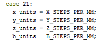
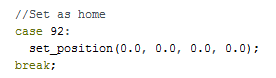
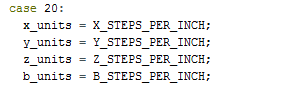
Figure 6d. More modification in the case statements to be consistent with the rest of the stepper motors.
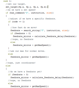
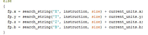
Figure 6d. Added variables in the process_string.ino file to read any G-Code commands.
The screenshot of Case 92 as shown above was modified so that the origin of the variable is not only X, Y, and Z but also zero’d for A. Hence, we see that there are 4 values of ‘0.0’.
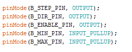
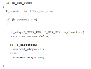
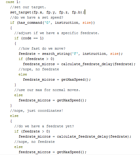
Figure 6e. Addition of A-Axis code in the stepper_control.ino file.
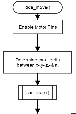
Limiting Switch Feedback
Similar to the X-Axis and the Y-Axis control, we decided to set a limiting switch for the Z-axis to check whether it goes too far up. In the stepper_control.ino file, there is a function called dda_move (). A portion of the code checks whether the limiting switches have been hit at the end of the working area. Fig. 7 shows the portion where the limiting switch for the Z-axis is added. The Z-minimum pin was not used, but had to be included to remain consistent with the amount of variables added to the function.
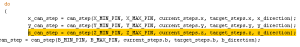
Figure 7. Limiting switch Arduino code added under the dda_move() function.
Microservo Control
For our reel feeders, we decided to attach reel wheels onto four microservos. To control out microservos, we decided to create our own case statement for the Arduino to process in process_string.ino.
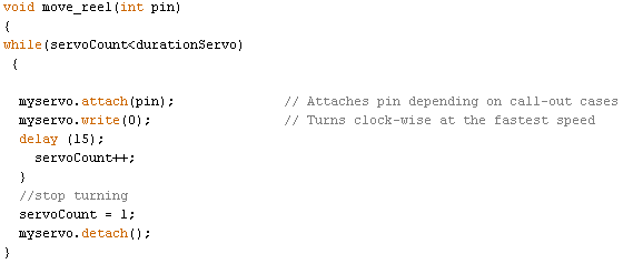
With the help of our president, Ryland Watts, we were able to utilize a while statement. His while statement required delays, which we didn’t want to use. A subroutine was created and called out when ‘$’ statements were provided in the process_string.
Table 1 shows the customized code we added. Fig. 8 shows our subroutine.
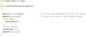
Figure 8. Subroutine move_reel gets called out when ‘$11’, ‘$12’, ‘$13’, or ‘$14’ is in the serial monitor.
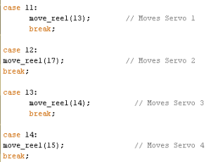
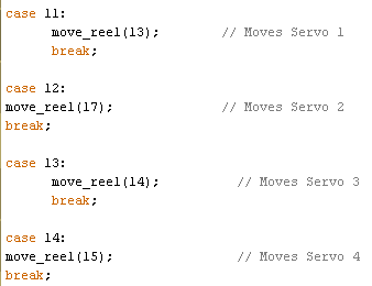
Figure 9. Case statements for servo control.
In process_string.ino, the move_reel subroutine is called out if the inputs of the ‘$’ are created.
Solenoid Valve Control
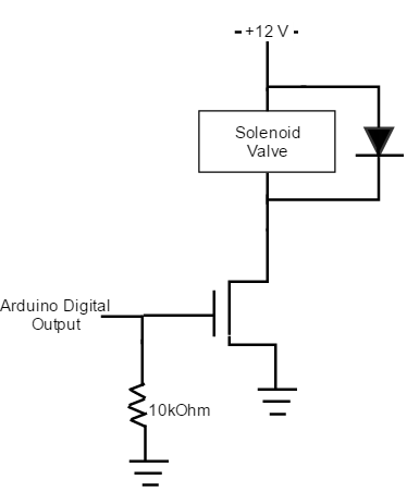
For the solenoid valve, we are considering on controlling the value using an n-channel MOSFET. This was based on the lesson taught by Ryland Watts, where we learned how to control DC motors with Arduino digital pins.

Figure 10. Solenoid Valve Circuit for Arduino
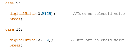
The following code is in the process_string.ino, where ‘$9’ and ‘$10’ turns the solenoid valve on and off, respectively. The 12 Volts attached to the solenoid valve is the rated voltage at which the solenoid valve will turn on.

Figure 11. Case code to activate the solenoid valve off and on.
Conclusion
The summary of software modifications required thorough understanding of our coding goals and what was already implemented in the Makeblock Arduino code. With the help of our president Ryland Watts, we were able to complete our software modifications.