
by:
Peiyuan Xu (Project Manager)
Nicholas Lombardo (Project Assistant)
Introduction:
This spring 2016 Pathfinder project will use Google’s Project Tango as a platform to test and implement SLAM (Simultaneous Localization and Mapping) technology for autonomous vehicles. Project Tango uses computer vision to give device the ability to know the position in the relative 3D space as well as the distance from the surrounding objects to the device itself.
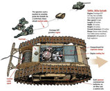
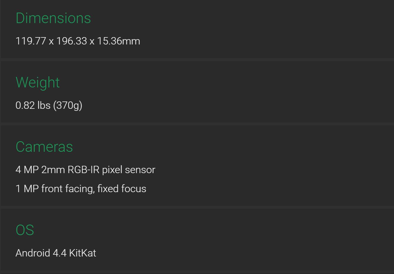
Physical Description
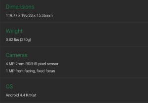
The Tango tablet has a physical dimension of 119.77 x 196.33 x 15.36mm.
The weight is 0.82 lbs (370g)

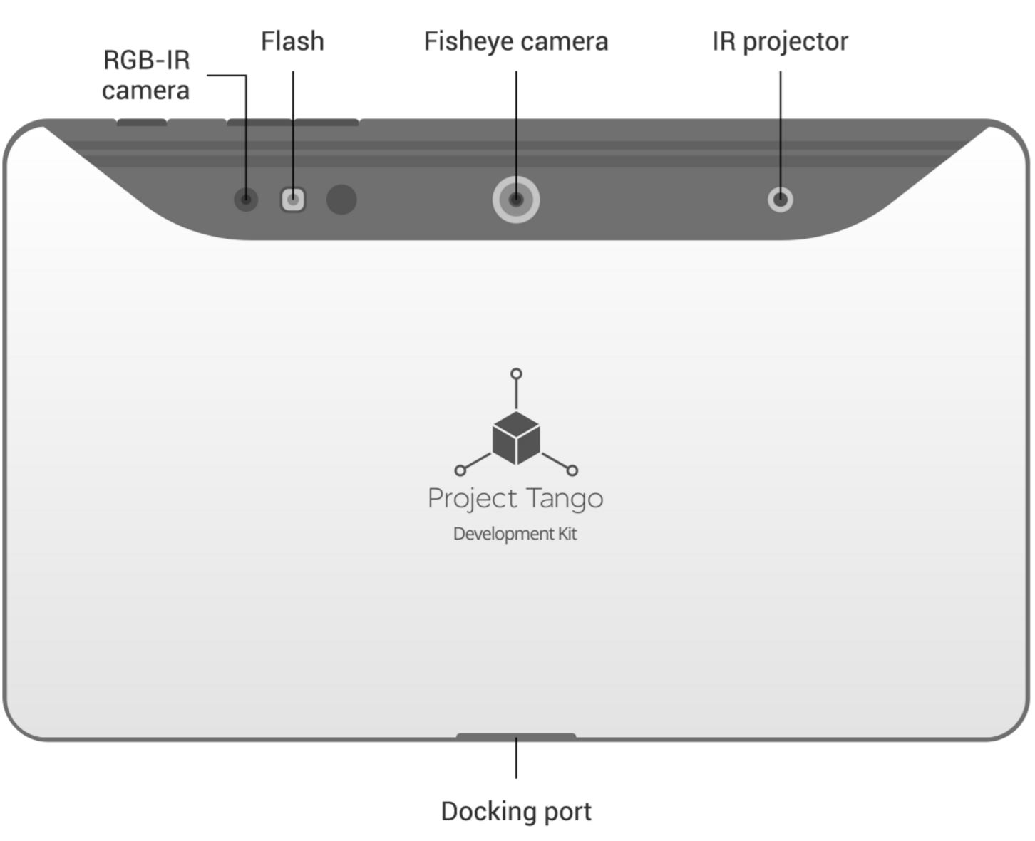
On the back of the tablet, it has a fisheye camera placed in the middle with an IR projector on the right and a RGB-IR camera on the left. The IR projector and RGB-IR camera work together with IMU (Inertial Measurement Unit) sensors to perform the features of Motion Tracking, Depth Perception and Area Learning.
Key Features
The IMU is used to give feedback on the device orientation and spatial displacement from a reference point. The Motion Tracking feature is usually achieved by integrating readings from orthogonally placed gyroscopes, magnetometers, and accelerometers.
Learn more about Motion Tracking
Tango’s Depth perception can provide feedback on distances between the device and nearby solid objects. Tango uses an approach called structured light sensing where a pattern of light is cast and the size and shape of the pattern seen by the camera is used to determine the distance.
Learn more about Depth Perception
Tango’s Area Learning feature helps with motion tracking by correcting drift and helps with navigation of indoors applications. It uses image processing of visual features in a virtual environment to recognize a previously-visited location.
Learn more about Area Learning
Limitations:
- The IR sensors for depth perception is generally restricted to indoor environments (sun and incandescent IR light can drown out structured light sensing). Therefore, in order to accomplish the requirements for both solar panels implementation (under direct sunshine) and Tango applications (without sunshine), the mission course is changed to be at CSULB campus during night time.
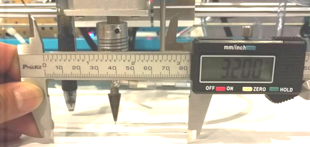
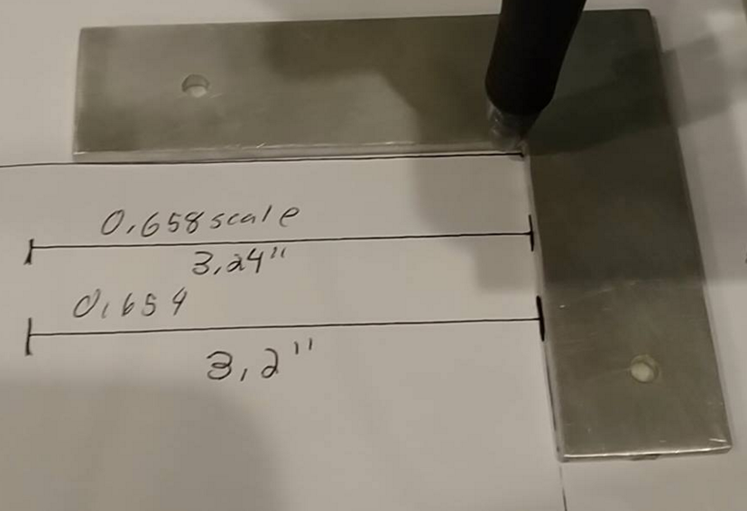
- Range of IR sensors practically limits its use to nearby obstacle detection rather than long-range path creation. The range of the IR sensor is from 0.5 meters to 4 meters based on Project tango’s website.
Power Test For Tango Tablet
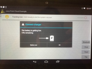
The purpose of this test is to gain the power specs while running point cloud App, screen on, bluetooth on, WiFi on for worst case.
The result shows that it takes about 2 hours and 16 minutes to run the battery from fully charged (100%) to 14%. In which case, it dose not meet our level 1 requirement of running for 4 hours. Also it is recommended to use a high-power 2A USB hub to charge the Tango Tablet.
Therefore, in order to meet the level 1 requirement, an extra portable charger (Power output: 5V, 2A) with Micro USB cable will be used to charge Tango tablet continuously during the mission.
Reference:
Get started with Project Tango
Notice that Project Tango offers APIs in C and Java, and a SDK for Unity. For developers who are already familiar with Android studio and Java development, the Java API is the one to use. Developers who want to be able to write apps with the Android NDK (Native Development Kit) should use the C API, which enables more flexibility on the native and system level. The Unity SDK is good for game development in 3D virtual environment.
Learn more on API Overview
Tutorials can be found here:
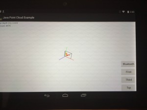
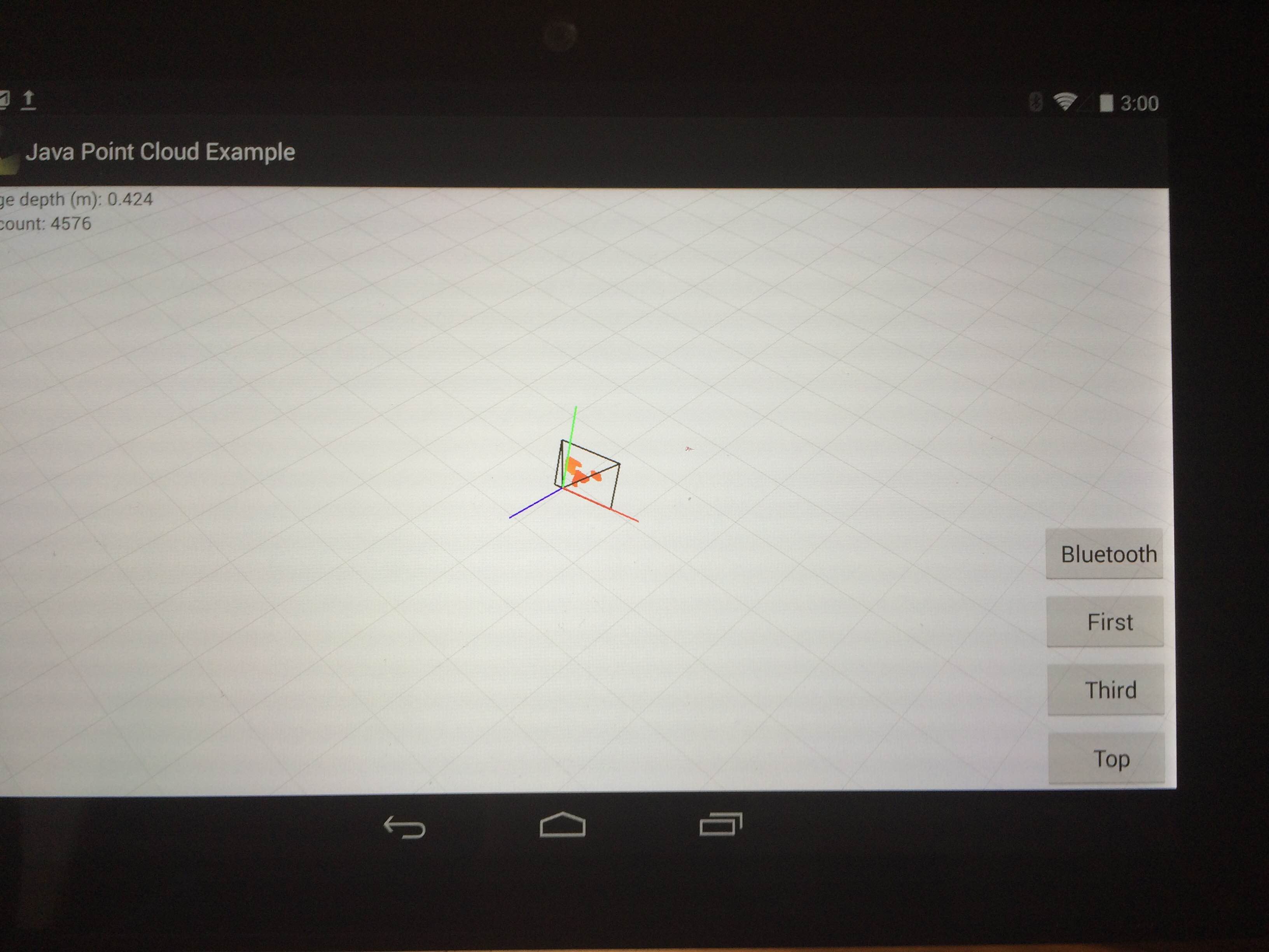
Once you have downloaded the sample code and successfully installed the App. you will see a window like this:

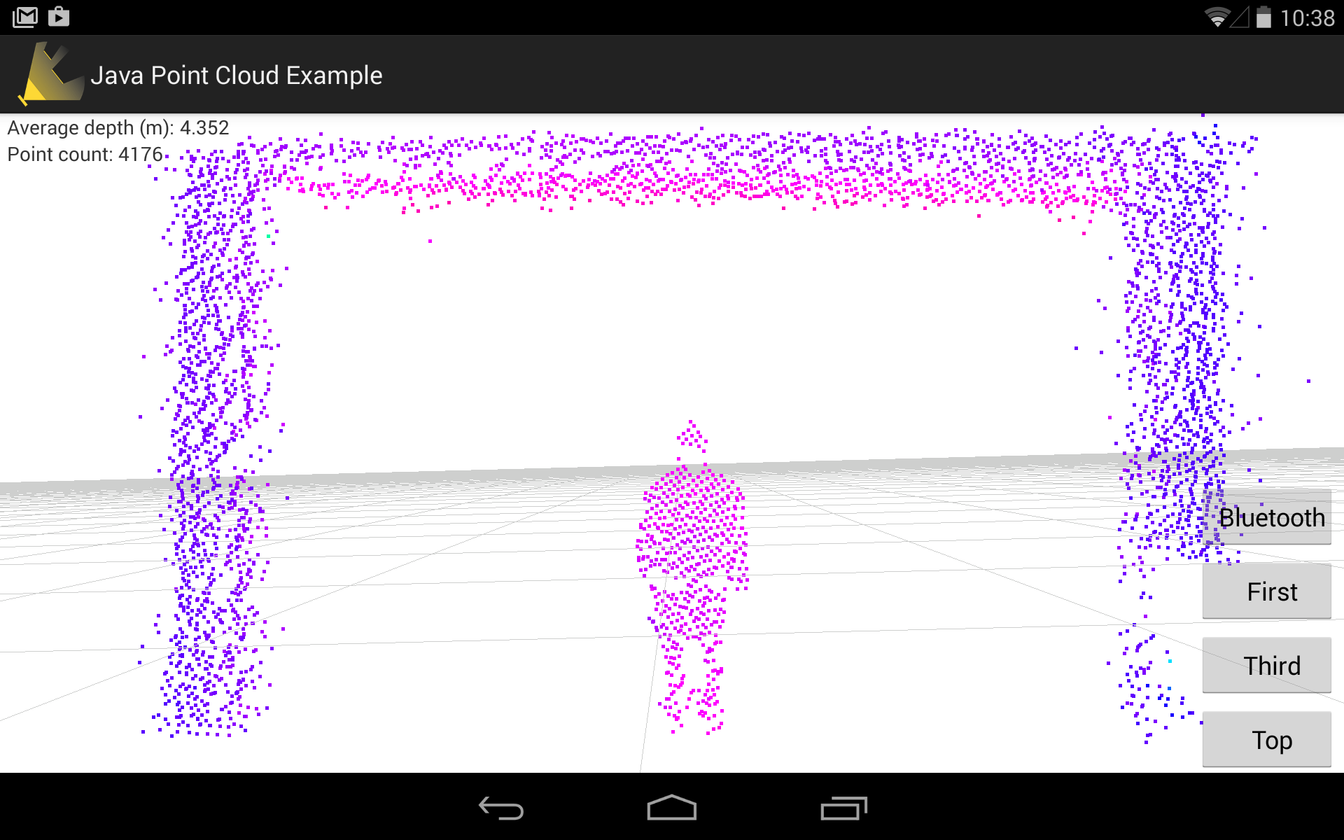
This is the Point Cloud version of a person standing in the Hallway. On the top left, It states that “Average depth(m): 4.352” which means that person is about 4 meters away from the tablet.
On the right side, there are 4 buttons. The first “Bluetooth” button is the custom button that I made in order to connect the tablet to Arduino through BlueTooth while running the Java Point Cloud App. Below the “Bluetooth” button, there are the three buttons that can switch from different orientation and give different point of view of the Point Cloud data.
After we have done that, now it is important to understand how the system should work between Project tango and Arduino and then eventually implement the software modules on Arxterra.
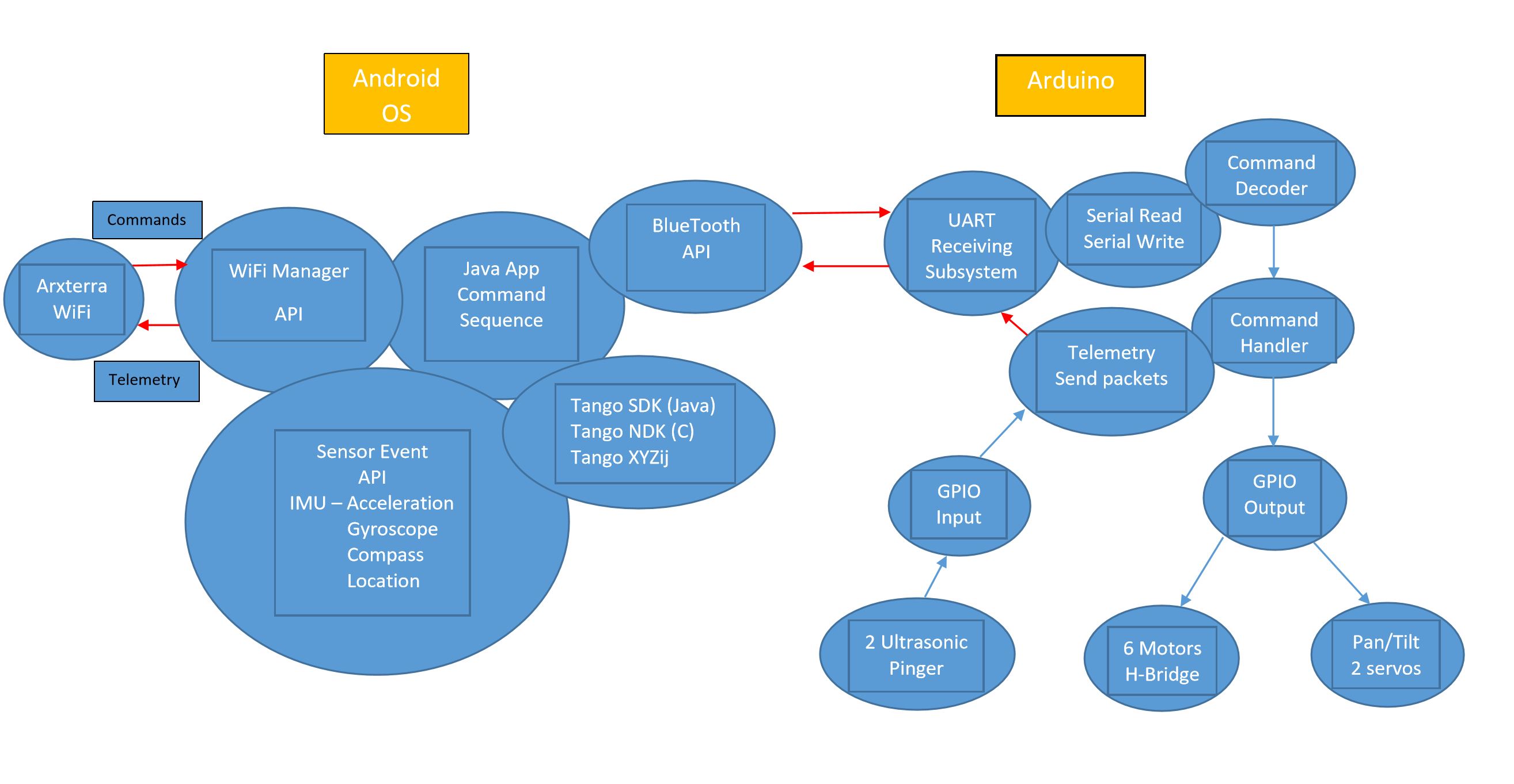
Project Tango System Block Diagram

Above is the Project Tango System Block Diagram that provided by Professor Hill. The diagram is divided into two parts. In the Android Operating system, commands will be sent by Arxterra to WiFi Manager API and decoded in Tango Android OS. Then the main point cloud App will process the coordinates and position information from Sensor Event API and Tango XYZij structure and send feedback telemetry back from WiFi Manager API to Arxterra. In the Arduino part, Java Point Cloud App will send command sequence through bluetooth to UART subsystem decoder and then to Arduino board. Then the microcontroller (Arduino mega) will send serial read/write to command decoder to command handler and then to GPIO to control the Ultrasonic sensors, H-bridge motors and servos. From that, our team develop the software modules and tasks breakdown to accomplish the system design.
Software Modules and Task Breakdown
Module 1: Sending commands to WiFi Manager API (Through “cool term”)
Module 2: WiFi Manager API sending telemetry out to Arxterra
Module 3: Tango SDK or NDK (Translate XYZij to Tango)
Module 4: SensorEvent API (IMU)
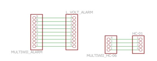
Module 5: BlueTooth API to HC-06 Module to Arduino
Module 6: Arduino to HC-06 to BlueTooth API
Module 7: Arduino Command Decoder to Command Handler
Module 8: Arduino Command Handler to GPIO Output to Motors and Servos Control
Module 9: GPIO Input to Telemetry Send Packets to UART Receiving Subsystem to Android OS
Module 10 Java App Command Sequence Development
More on IMU and Coordinate System
Module 3 requires to understand the IMU (Inertial Measurement Unit) and Project Tango Coordinate Frames. The links below explain the Tango Coordinate System Conventions
Coordinate System Convention
The next link explains Android devices IMU sensors in general that includes Tango Tablets as well
Sensors Overview
Research into PCL and ROS
Module 10 requires knowledge of processing point cloud data. This may be as easy as importing a library and using the defined classes/methods for data manipulation.
The PCL (Point Cloud Library) and ROS (Robot Operating System) are both open sources that offers libraries and tools to analyze point cloud data. Many companies and developers are working on building application with PCL or ROS for Project Tango. Some useful Tips and tutorials can be found here:
How to build applications with PCL for Android
Getting Started with Tango and ROS
PCL Documentation
Conclusion
The use of Project Tango tablet is ambitious since it is fairly new and requires extensive knowledge of Android App development and Java Programming. In this semester, our team is able to attempt and finish some of the Project Tango modules, that includes “BlueTooth API to HC-06 Module to Arduino (Blinking LED and Motors Control)”, “Extract Point Cloud Data from Tango and process with Paraview software”. We will have upcoming blog posts to explain and show the steps of how these modules can be done. We hope the research work we have here can benefit the future groups or individual who wants to continue work on Project Tango.
Source Materials:


