Ultrasonic Field of View Test

By: Jordan Smallwood (Project Manager and Electronics & Control)

Approved By: Miguel Garcia (Quality Assurance)

Table of Contents


Introduction

In order to develop an object avoidance routine we needed to verify that the ultrasonic sensors would work for detecting objects. To verify the field of view a simple experiment was constructed that would determine the distance to an object. The experiment is as follows.


Parts Required:

  1. HC-SR04 Ultrasonic Sensor
  2. Arduino (Any will do)
  3. Serial Monitor
  4. Ruler or other measuring device
  5. 2 LED’s with CLR’s

Figure 1: Fritzing Diagram for FOV test


Setup:

The ultrasonic sensor has 4 pins: VCC, GND, Trig and Echo. Vcc and GND are for powering the device where as Trig and Echo are the signal pins. Trig is short for trigger, applying a pulse to this pin will emit an ultrasonic ping that travels from the transmitter. The echo pin is where you receive the ping coming off the object of interest. The time delay that takes place between these steps will determine how far away an object is. For our setup, Trig was hooked up to pin 13 and Echo was hooked up to pin 12 but any digital pins will work.

Next upload the code provided to get an output from the Serial Monitor showing the distance to the object.


Figure 2: Code for FOV test


Determining Field of View:

In order to determine the field of view of the object two rulers were set up to determine when we lost sight of the object. The object was recognized directly in front of the sensors at x = 16 cm and then moved up and down in the z-direction. The sensor lost sight of the object at about 6 cm above or below. The same situation took place when the object was moved along the y-direction. From this we can gather that the field of view is about 18 degrees.

Figure 3: Determining Safe Object Detection Distance

              The distance L is the safe object detection distance. If we detect anything closer than that is when we lose overlap between the sensors which means that we could run into trouble if anything gets closer than that. The distance can easily be found as:

Figure 4: Determining Safe Distance L


Conclusion:

The Ultrasonic sensors are actually pretty impressive. I’ve never uploaded code and received immediate results, this was a first for me. I would put my hand in front of the sensor and compare the actual distance to find they were very comparable. With these sensors we can easily detect if an object is too close and from that we can implement some kind of avoidance strategy.


References

http://www.instructables.com/id/Simple-Arduino-and-HC-SR04-Example/

BEAR-ings

By: Jordan Smallwood (Project Manager and Electronics & Control)

Approved By: Miguel Garcia (Quality Assurance)


Probably the coolest part in most mechatronic designs would have to be bearings. They’re simple but confusing and very amusing, at least for me. There are many different types of bearings in all different shapes, sizes, colors, and functionalities. The reason for this blog post is that one of the main issues with the Pathfinder build was the lack of knowledge when it came to constructing the rocker-bogie mechanism. Let me begin by saying that it is in no way previous semester’s fault for not understanding this since we are electrical engineering students.

There are two main types of bearings, thrust and radial, from those branch various specifications about each one in regards to size, forces, and speed. However, the scope of this post is to enlighten those who are concerned about which type of bearing to use.

Figure 1: Different Loads Acting on A Bearing

Thrust bearings are the type of rotary bearing that allow parts to rotate about the other but unlike their radial counterparts they are designed to support axial loads. Axial loads are forces that are applied in the direction of the shaft.

Figure 2: Example of a Thrust Bearing

Radial Bearings are the opposite and they support, wait for it, radial loads! These bearings are common and you have probably used them once or twice whether they were in your skateboard or roller blades.

Figure 3: Example of a Radial Bearing

The issue with the build of the Pathfinder is that the load on the rocker-bogie mechanism is axial and the type of bearing placed on them was a radial bearing. This radial bearing was essentially acting like a spacer between parts since they were making contact with both rotational elements. To improve the design we obtained some inexpensive thrust bearings off Amazon and they have solved the problem.


References

  1. https://www.ggbearings.com/en/faq/what-are-radial-and-axial-bearings
  2. https://qualitybearings.wordpress.com/2010/08/31/bearing-load-type/
  3. http://www.bearingshopuk.co.uk/lt-5-8-thrust-bearing/
  4. https://www.vxb.com/ML-5008-Radial-Bore-Dia-5mm-OD-8mm-Width-2mm-p/ml5008.htm

6 Wheel Electronic Differential

By: Jordan Smallwood (Project Manager and Electronics & Control)

Approved By: Miguel Garcia (Quality Assurance)

Table of Contents


Introduction

Have you ever considered how a train makes a turn? Really try and think about it, it has two wheels on a track separated by a distance but when it turns it doesn’t fly off the track. It’s not very intuitive but if a train was making a right turn, going along a curve to the right, the left wheel is traveling a greater distance since it’s on the outer curve. However, the two wheels traveling along the track are joined by a steel shaft that doesn’t break. So, what is the explanation for this phenomenon?

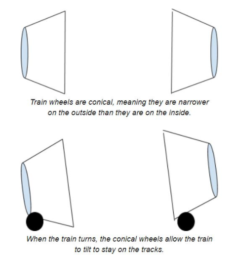
Figure 1: Differential Explanation

              Trains have conical wheels that allow for this freedom of motion at the track, they slide back and forth along the track allowing the train to tilt one way or the other. Now, the Pathfinder is not a train and will not be riding along tracks, but the same concept applies.


Encoders

The Pathfinder has 6 motors all connected to the same power source and in a perfect world if we supplied each of these motors with the same PWM command they would all go the same speed. However, this is not a perfect world and many factors can come into play when it comes to how fast the motor spins. First off, the whole premise behind the Pathfinder is that it can climb objects asymmetrically, that is each motor can be experiencing a different load which is one of the major reasons behind needing an electronic differential. Secondly, when we make turns we want to make sure the wheels are going at the speed we want them to account for the difference in distance traveled. And finally, due to natural mismatch in motor build we need to examine the difference in speed of the motors.

Herein lies the problem we have faced and have tried to come up with a solution for the past month or so. The motors on the Pathfinder currently do not have any encoders. We have looked at every possible type of encoder such as magnetic, optical, and any other possible type but we have finally realized that the only way of getting a truly good output from the encoder is by purchasing motors that already have encoders installed. The reason behind this is simply to achieve the greatest possible resolution with your encoders is to get your output prior to the gearbox. I can not stress that enough. If you ever have a project that you need encoders on make sure you either buy motors with an extended shaft or motors that have encoders included otherwise you might find yourself in the same situation. $200 later we now have our encoders.


Hall Effect Sensors

Now that we have motors with encoders connected prior to the gear-box we need to understand how they work.

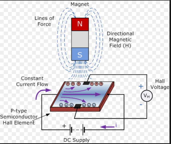
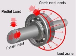
Figure 2: Diagram of Hall Effect Sensor

              In the presence of a changing magnetic field, a charged semiconductor plate will deflect the flow of electrons from one side or the other. Consequently, one side of the plate will become more negative while the other becomes more positive. This is the basic principle of how a hall effect sensor works. A magnet is placed perpendicularly to the sensor plate and the Hall Voltage on the plate is observed. This is typically found in many encoding applications. There are two different types of Hall Effect sensors available, one that is a measure of flux density and the other is compared against some threshold voltage. We will be utilizing the latter since we are only concerned with the count and not the distance to the magnet. Another great feature of hall-effect sensors is their ability to toggle between states which means that bouncing is not an issue.

The encoders that we have paired with our motors have 6 pins associated with them, they are as follows:

  1. M1 (Motor Power Supply 1)
  2. GND (Encoder Ground)
  3. C1 (Encoder Channel 1)
  4. C2 (Encoder Channel 2)
  5. VCC (Encoder VCC)
  6. M2 (Motor Power Supply 1)


For each revolution of the motor we will receive 11 counts per channel which results in 22 CPR overall. Depending on the gear-box reduction ratio, which in our case is 280 (14 RPM), we can calculate the resolution as follows:

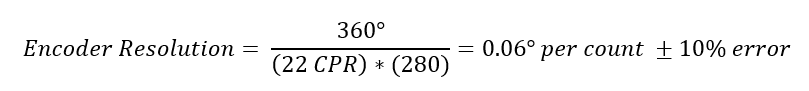
Figure 3: Determining the Resolution of Shaft Encoders

Note that this is the maximum resolution and there is an included error from the motor manufacturers data sheet. Depending on the amount of precision you need you can always use both channels, also if you need to determine direction of the motors then you will need to use both channels. For our purposes though we will only need to occupy one channel since pin allocation has become something of an issue for us.
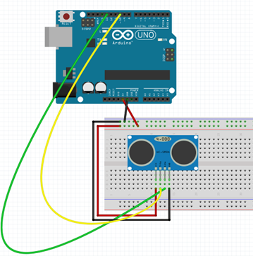

Implementation

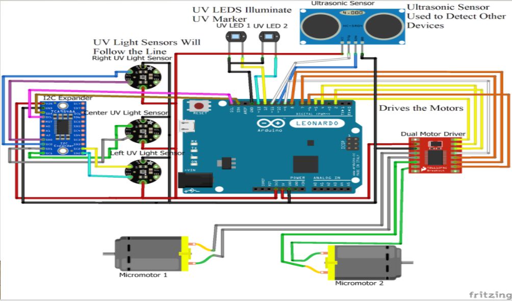
To accurately and efficiently read the encoders we will be using interrupts. By using interrupts we can allow the code to progress as normal and minimize the amount of time outside of the main loop. In order to make this 6 wheel differential work we have two options.

  1. We can set a desired speed that the robot travels and make all 6 wheels track that speed, or try to stay within a certain margin of that speed.
  2. We can set one of the motors to a certain PWM value that we are comfortable with and force the other 5 motors to follow that speed.

The issue with the second option is that even though we are sending a constant speed to one motor, it could fluctuate about some speed and that can cause issues with our control scheme. There is much less error when tracking a step input rather than a varying signal. Therefore the plan of action will be to set a desired speed, within capable limits of the motors, and make each motor follow that desired state.

In order to realize this we are going to need to design a controller that can follow this input. In my experience one of the easiest types of controllers to implement would be a proportional controller. Proportional control is relatively simple and comes at a low cost to the memory of our MC.

After running some experiments and playing with the gain we can figure out exactly how to implement this type of controller. For our purposes we will have 6 controllers, one for each of the motors. The input will be a constant velocity and the output from the encoders will be fed back to the summing junction to compare with the set point.
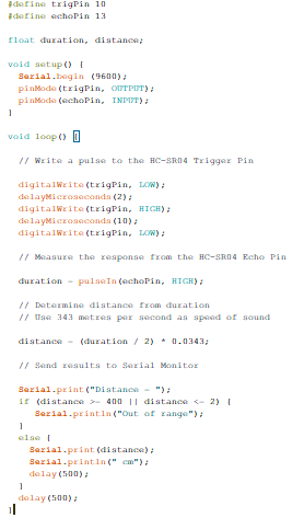

Software

Reading the Encoders

To efficiently read the encoders we will need to set up some interrupt service routines, specifically one for each motors encoder channel. This will be done similar to the following code:

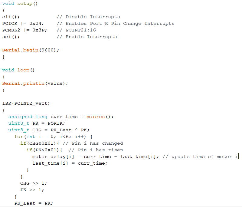
Figure 4: Code for reading the encoders

              To get more information on how to set up interrupts like this please refer to the blog post regarding them HERE.

To verify that the output from the ISR was correct I applied a test voltage from a power source and found that the elapsed time between pulses was about 1450 microseconds for the 14RPM motors. After playing with the values and factoring in the gear ratio and CPR values the no-load speed of the 14 RPM motor was approximately 13.4 RPM which verified that these encoders are providing good feedback.
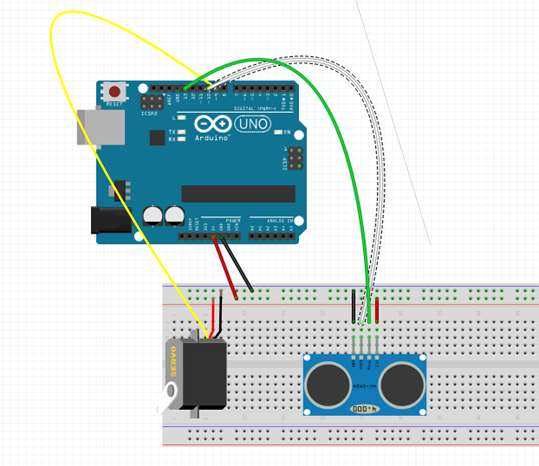

Control

              Knowing the limitations of your control is important when it comes to implementing a design. For example, we know that these motors can spin without any load at a maximum of about 14 RPM. So, we want to travel at a speed that will allow for the system to adjust for disturbances such as changing loads, error in sensor readings, and anything else that might present itself. Therefore, we will set the desired speed to a comfortable 10 RPM, this will allow the system to adjust in both directions.

We can include different equations in our ISR to calculate the speed but it would be easier if we just returned the delay between pulses and let the control track that instead. For a speed of 10 RPM it can be shown that the delay is about 1,950 micro seconds. If the actual speed of the motor is greater than 10 RPM then the delay would be less and if the motor was traveling slower the delay would be greater. Also, if we wanted to apply a gain to the controller we would need to come up with something that makes sense. If one of the motors was traveling faster than the set point by 1 RPM then that would translate to about 100 microseconds so if we wanted to allow the controller to respond aggressively to large errors a gain of about 4 would do the trick. With all of that in mind we can construct the controller as follows:

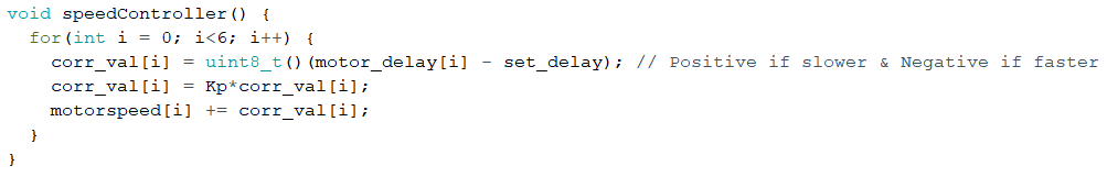
Figure 5: Code for Speed Controller


References

  1. https://www.arxterra.com/pin-change-interrupts/
  2. https://thewanderingengineer.com/2014/08/11/arduino-pin-change-interrupts/
  3. https://www.arduino.cc/en/Tutorial/BlinkWithoutDelay
  4. https://sciworthy.com/why-trains-dont-fall-off-the-track-when-turning/
  5. https://www.electronics-tutorials.ws/electromagnetism/hall-effect.html


Spring 2018 3DoT Hexy: Prototype Fritzing Diagram

By: Kris Osuna (Electronics and Controls Engineer)

Verified by: Eduardo De La Cruz (Project Manager and Manufacturing Engineer)

Approved by: Miguel Garcia (Quality Assurance)

Introduction

We used the open source fritzing software to create a prototype that will show all connections to an Arduino Leonardo. The Leonardo is used because it uses the same processor as the 3DoT board. The Leonardo provides 3.3V to the pins which is less than the 3DoT board provides, so if it works on the Leonardo it will work on the 3DoT board. The prototype will be able to move with motors connected to a dual motor driver to control the motors. Three UV sensors will be connected with three UV LEDs. The UV sensors and LEDs will help the robot navigate the maze. An I2C multiplier for the serial data is needed. An ultrasonic sensor is needed with two digital pins. The ultrasonic sensor will detect other obstacles.


Related Requirements

Level 1 Requirements

  • The robot will need to navigate remotely through a custom-built maze (built by AoSa image), memorize the path it took, start over, and autonomously travel through the path it took.
  • The robot shall avoid collisions if it encounters other robots while navigating through the maze. This involves detecting the robot, retracing steps back, and moving to a room that allows the other robot to have a safe passage.
  • The robot shall use a v6.43 3DoT board.
  • The robot shall demonstrate the capabilities of the 3DoT micro-controller for DIY hobbyists.

Level 2 Requirements

  • The robot shall use a single RCR123A 3.7 V, 650mA rechargeable Li-ion battery to power the 3DoT board, which will power the drivetrain and all attached peripherals.
  • The robot shall use 2 UV sensors connected to a custom PCB.
  • The robot shall use a HC-SR04 ultrasonic sensor to handle robot avoidance.
  • Ultrasonic sensor shall have a range of 0.5-meter radius to detect and respond accordingly to other robots.

Preliminary Design Fritzing Diagram (March 08,2018)

Figure 1: Preliminary Design Fritzing Diagram 

Resources

  1. Fritzing Tutorial
  2. Sparkfun Fritzing Library

Spring 2018 3DoT Hexy: Assembly (Prototype/Final)

By: Eduardo De La Cruz (Project Manager & Manufacturing Engineer)

Approved by: Miguel Garcia (Quality Assurance)

Table of Contents

Introduction

The purpose of this blog post is to demonstrate how all parts designed in Solidworks were put together along with other outsourced materials. We will be assembling two  models of our robot: the prototype which is based of our preliminary design review design and our final design which can be found in “Spring 2018 3DoT Hexy: 3D Model”.   

Related Requirements

C-03:

The robot will be designed to be a toy for people ages 8+.

C-04:

In order to minimize manufacturing cost, and packaging cost the robot shall be able to be constructed from sub assemblies within 10 minutes.

Assembly of Final Model – (May 07, 2018)

Parts

3D Printed Parts:

  • x1 – Sensor Enclosure
  • x1 – Hardware Enclosure
  • x1 – Top plate
  • x1 – Bottom plate
  • x1 – Cable tube
  • x2 – Left Femurs
  • x2 – Right Femurs
  • x2 – Middle Femurs
  • x6 – Tibias
  • x6 – Femur-to-gear


Components Outsourced:

  • x22 – 3 -.5 mm nylon lock nuts
  •  x6 – 3 -.5 mm hex nuts
  • x10 – 3 -.5 mm x 16 mm flat head machine screws
  • x12 – 3 -.5 mm x 20mm Socket cap screws
  • x6 – 3 -.5 mm x 16mm Socket cap screws
  • x12 – 8 mm x 4 mm OD x 3 mm ID aluminum bushings  
  • x10 – 3 mm ID brass plated bushings
  • x16 – 3mm x 6mm (ID/OD) (#4) washers
  • x10 – 3mm x 8mm (ID/OD) (#6) washers
  •  x4 – 3 -.5 mm x 45 mm socket cap screws
  •  x4 – 1’ x ¼ ‘’ OD nylon spacers
  •  x2 – Actobotics micro gear motor enclosure
  •  x6 – 30T Ajax Scientific plastic gears
  •  x4 – 10T Ajax Scientific plastic gears
  •  x2 – Driving gears
  •  x2 – 530 RPM micro gear motors
  • x10 – VxB 3 x 6 x 2.5 mm bearings


Required tools:

  • Philip Screw Driver
  • 3 mm hex nut driver
  • 3 mm allen key


Steps 

Note: The leg assembly, which is the tibia, femur and gear will be advertised as a single piece to reduce assembly and disassembly times. However, for the purpose of this blog post we will go through the leg assembly for reference purposes.


Leg Assembly

Step 1: Connect the tibia to the femur and fasten them using a 20 mm socket cap screw and a hex nut.


Step 2: Connect the femur-to-gear joint to the gear and fasten them together by running a 16 mm socket cap screw with a #4 washer through the bottom of the gear and fasten them together using a lock nut.


Step 3: Connect the other end of the femur to the gear-to-femur joint using a 20 mm socket cap screw and a lock nut.


Step 4: Adjust how tight each screw is to achieve the best movement


Final Assembly


Step 1: Run a 16 mm flat head machine screw through the bearing bore of the gear, add a brass bushing and a washer through the other end of the screw, and fasten this assembly to the chassis using a lock nut and #6 washers.


Step 2: Connect the legs to the chassis leg guides


Step 3: Connect the top plate to the bottom plate using 45 mm socket cap screws, 1 inch spacers, and lock nuts.


Step 4: Connect the sensor enclosure to the chassis by using the same 45mm socket cap  screws to one end of the chassis.


Step 5: Attach the motor enclosure to the bottom plate.


Step 6: Attach the cable tube to the back using the custom mount fabricated and using a 3 mm screw.


Step 7: Place the hardware cover which should clip on by the use of magnets.


For instructions on installing the hardware, reference the system integration and testing post.


Final Assembly   

Assembly of Hexy Mk-01 (Prototype) – (April 3, 2018)

Figure 1: 3DoT Hexy Mk-01 Parts 

Parts

3D Printed Parts:

  • x1 Bottom Plate
  • x1 Top Plate
  • x2 Left Femur
  • x2 Right Femur
  • x2 Middle Femur
  • x2 Middle Tibia
  • x4 Outer Tibia
  • x6 Femur-to-Gear joint


Components:

  • x6 cotter pins
  • x10 3-.5 mm nylon lock nuts
  • x4 3-.5 mm hex nuts
  • x6 2.5 x 15 mm machine screws
  • x10 3×15 mm machine screws  
  • x4 3×30 mm machine screws
  • x4 3.5 x 15 mm sheet metal screws
  • x6  30T Ajax Scientific plastic gears
  • x4 10T Ajax Scientific plastic gears
  • x2 10T Driving gears  
  • x2 530 RPM micro gear motors
  • x2 Actobotics micro gear motor enclosure
  • x6 5×2 mm sheet metal screws
  • x4 20 mm x 3.5 mm (length/inner diameter) spacers
  • x6 3 mm x 10 mm (inner/outer diameter) washers
  • x4 3 mm x 6 mm (inner/outer diameter washers)


Required tools:

  • Philip Screw Driver
  • 3 mm hex nut driver
  • Flat tip pliers


Recommended:

Figure 2: Lucas Red “N” Tacky

Adding Lucas Red “N” Tacky grease before inserting gear shaft screws and to the gears themselves improves the performance of the cam system by reducing friction between parts.


Steps

  1. Connect femur-to-gear joint to gears. Insert 5×2 mm sheet metal screws into designated gear hole. Connect joint to gear by screwing it in until the joints bottom face comes in contact with the gear.Figure 3: Assembling gear-to-femur joint 
  2. Place Washers and gears over gear holder holes. Note 3 x 10 mm washer go on 30T gears and 3 x 6 mm washers go on 10T gears.  Figure 4: Placing washers 
  3. Insert 3×15 mm machine screws and place nylon lock nuts on the underside. Screw in nylon lock nuts, using 3 mm hex nut driver, to a desirable position that is not to tight to prevent gear rotation. Note: Adding grease to screw shaft and gear improves cam performance. Figure 5: Placing gears, screws, and lock nuts  
  4. Assemble legs. Mate the femur to the tibia to form elbow joint. Insert 2.5×15 mm machine screws to hold joint together. Figure 6: Assembling legs 
  5. Adding legs to cam system. Connect legs to femur-to-gear joint using cotter pins. After inserting cotter pins use flat head pliers to pry open the endpoints of the cotter pins. Figure 7: Adding cotter pins 
  6. Insert micro gear motor enclosures to the underside of the bottom plate and screw them in place using 3.5 x 15 mm sheet metal screws. Figure 8: Adding micro gear motors 
  7. Insert 10T Driving gears from the top plate and insert micro motors from the bottom plate. Since we are using the method A driving gear design (read above) we will need to apply a little pressure to insert gear with bushing into the shaft of the motor. Figure 9: Adding driving gears 
  8. Insert femur’s center opening on the aluminum rods (as shown above)
  9. Place top cover, align it with the bottom plate, insert 20 mm spacers in each corner, insert 30 mm machine screws in each corner, and screw hex nuts to screws from the underside of the bottom plate. Figure 10: Adding spacers, screws, and hex nuts
  10. Run motor wires to the top plate.

Assembled Prototype

Figure 11: Hexy Mk-01

Resources


Pin Change Interrupts

By: Jordan Smallwood (Project Manager and Electronics & Control)

Approved by: Miguel Garcia (Quality Assurance)

Table of Contents


Introduction

If you think back to your days of EE 346 you’ll remember the daunting feeling of dealing with interrupts. While we barely skimmed the surface, they’re really not that troublesome. The thing to note is that there are two types of interrupts, hardware & software. Hardware interrupts take place externally from the chip such as a physical button being pressed or any kind of input changing state. Software interrupts occur internally and most likely will be the result of a timer. Hardware interrupts can be further broken down into two more categories: external interrupts and pin change interrupts. Although pin change interrupts are technically external the difference with these is that they are not pin specific, the ISR corresponding to that pin will be called any time the condition is met from any pin on that port tied to the ISR. This can be more difficult to work with than the regular external interrupts which are pin specific but the advantage of using this type is that for most AVR boards any pin can be configured as a PCINT.

For our purposes we needed six interrupts, one for each of the motors encoders and although the ATMega 2560 has 6 external interrupts two of them were on the same pin as the I2C pins SCL and SDA which meant we needed to learn something new. Which leads us to a brief discussion of PCINT.


STEP 1: Turn on Pin Change Interrupts

To turn on PCINT’s you need to configure the PCICR (Pin Change Interrupt Control Register) according to your specific purposes. This can be done the following way:

Figure 1: Pin Change Control Register and description

Since we will be routing all of our encoders to PCINT23:16 it makes sense that we should enable PCIE2. To do so we will include the line of code: [PCICR |= 0x04]. This can be done many ways but the idea is that we set that pin to 1 while keeping the other bits unchanged.


STEP 2: Pin Selection

Although any pin mapped to PCI2 will run that ISR, that is only if we set their masked bits in the Pin Change Mask Register. We only need to use 6 of the 8 pins mapped to PCI2 so we can still use the other analog-in pins if we need to later.

Figure 2: Pin Change Mask Register 2 Description

Again, we only will be wiring encoders to PCINT 16:21 so we will need to include the following line of code: [PCMSK2 |= 0x3F;].


STEP 3: Write the ISR

Now that you have configured your interrupt control registers and decided which pins are going to actively set the ISR all that is left is to tell the computer what to do when it reaches this state. Any time you ever write an ISR you should keep it as short as possible and when declaring variables make sure to make them of type volatile so it is never optimized. To define the ISR just include the following:

ISR(PCINT2_vect){} // Port K, PCINT16-PCINT23.

Finally, you will have something like this:

Figure 3: Pin Change Interrupt Example


References:

  1. https://thewanderingengineer.com/2014/08/11/arduino-pin-change-interrupts/

Spring 2018 AT-ST Sensor Testing

By: Shweta Hebbalkar (Electronics and Control – Hardware)

Verified By: Intiser Kabir (Project Manager)

Approved By: Miguel Garcia (Quality Assurance)

Table of Contents

Ultrasonic sensor – HC-SR04

Introduction

As the name implies this device uses an ultrasonic sound to measure the distance between itself and the nearest solid object. Like if we take the nature’s example then it would be like Bats detecting shapes from the sound. So with this key feature has become a staple in our projects because the last thing we want is for our project AT-ST to get the pushed out from the other robots.

Features

  • Operating Voltage: 5V DC 
  • VCC  = 5 volt power connection
  • Operating Current: 15mA
  • TRIG = trigger pin (input) 
  • Measure Angle: 15°
  • ECHO = Echo pin (output)
  • Ranging Distance: 2cm
  • 4m – GND = Ground

Theoretical Explanation of the ultrasonic sensor

Let’s look in more depth of this ultrasonic sensor so for our project we are using the HC-SR04 and it consists of two ultrasonic transducers one is used as the transmitter and another one is used as a receiver. Now when we normally operate the transmitter sends out a series of ultrasonic pulses remember the receiver despite its proximity does not pick up these pulses because ultrasonic signals are very directional. However, if an object in front of the device it will reflect the signals back to the receiver. The time delay that takes from the transmission and receiving the signal is used to calculate the distance so, for example, a longer delay will be considered as long distance and the shorter time delay will be the shorter distance. Now if we send the 5-volt, 10-microsecond pulse to the device then transmits 8 ultrasonic pulses either at the 40-kilohertz each. The echo pin will output a pulse between 100 and 50 – microsecond to 25 milliseconds and that pulse width is used to calculate the distance it will output a pulse of 38 milliseconds if there is no object detected.

Calculating the distance

To determine the distance ultrasonic signal travel at the speed of sound at 20 degrees Celsius the speed of sounds is 343 meters per second now remember the time we’re measuring with the HC-sr04 is for return trip so we’ll need to divide this in half to calculate the actual distance.

∆t=time delay

c=speed of sound (cm)

D=Distance Measured

D=∆t2*c  

As an example

D= (500/2) * 0.0343 = 8.575 cm

Experiment

Figure 1: Fritzing diagram with the Ultrasonic Sensor.

Code

Figure 2: Screenshot of the code

Output

Figure 3: Data from Arduino

Servo – Ultrasonic #1

Introduction

Servos are combined with the motor and also control electronics; this combination makes an easy to use package. The PWM signals with a periodic time of 20 milliseconds and a duty cycle of one to two milliseconds so five to ten percent. While an on time of one millisecond resents the -90-degree position of the motor shafts. 0-degree positions and the 2 milliseconds the +90-degree position. So we can rotate the shaft a total of 180 degrees. 

Features

  • Voltage: 4.8~6.0V
  • Torque: 3.5kg.cm@4.8V, 4.8kg.cm@6.0V
  • Speed: 0.17/60ТА @4.8V;0. 14/60ТА @6.0V
  • Size: 38.6×18.8×34.9mm
  • Wight: 37 g
  • Use Angle: <=160ТА

Figure 4: Fritzing diagram

Code


Figure 5: Screenshot of code

Output

Figure 6: Arduino output

Servo – Ultrasonic #2

Introduction

In this experiment, I created an object detector. So this module will scan from 0 to 180 degrees, and once its finish scanning the module will point at the object. If I displace the object, then the module will scan again from 0 to 180 degrees and trying to look for an object. This is one of the ideas for our project trying to avoid the other robots from the maze.

Fritzing diagram

Figure 7: Fritzing Diagram showing Servo and Ultrasonic

Code


Figure 8: Screenshot of code

Figure 9: Screenshot of code cont.

Output

Figure 10: Physical Demo of Servo and Ultrasonic

RGB led  

Introduction

Formerly, we were going integrate the color sensor to our robot. In order to require the decision either to take right, left, or keep going forward. Now, the color sensor is not required for our project because we change our maze requirements. But before that, I am going to explain the RGB Led to help me understand the color sensor little better. So, an RGB LED is a three LED’s in one basically 4 LED. This is a basic experiment to learn new circuit components and new programming skills.

Figure 11: RGB light connections on using fritzing diagram

Code

Figure 12: Screenshot of code

Output

Figure 13: The RCB displaying 3 different colors

Dc Motor

DC Motors that operate on direct current as opposed to motors, which operate on alternating current. We are using the small dc Motors for our project in order to move let’s look into how dc motor works. The shaft of the motor, the part that rotates is referred to an armature. On the armature, there are coils of wire these coils are connected to the commutator. The connections to the commutator are called the brushes, where the positive and negative voltage is applied. On the outside of the motor, there is a permanent magnet arranged in opposite magnetic polarity, now when dc current is applied to the commutator it sets up a magnetic field inside the coil. The coil magnets interact with permanent magnets causing the armature to rotate, now as the armature rotates the polarity is continually reversed generating the magnetic field to be reversed and the rotations to continue.

A motor driver module helps the dc motor with an Arduino, which means that dc motor will get the more current in order to, work, in other words, a current amplifier. So a motor driver is a breakout board, which consists of an L293D IC, the main purpose of the motor driver is to take a low current signal and convert it to a high current signal.

Conclusion

Due to some feedback from the Professor, we are not using RGB and will be using UV sensors with IR LEDs. We are using Ultrasonic as an avoidance mechanism. The DC motor is used to move our legs. We are planning to use servos to help control the center of gravity.

Reference

  1. https://cdn.sparkfun.com/datasheets/Sensors/Proximity/HCSR04.pdf
  2. https://www.sainsmart.com/products/ultrasonic-ranging-detector-mod-hc-sr04-distance-sensor
  3. https://components101.com/ultrasonic-sensor-working-pinout-datasheet
  4. https://www.radioshack.com/products/radioshack-standard-servo
  5. https://www.sparkfun.com/datasheets/Components/YSL-R596CR3G4B5C-C10.pdf
  6. https://nationalmaglab.org/education/magnet-academy/watch-play/interactive/dc-motor

Spring 2018 AT-ST Preliminary Model

By: Danny Pham (Manufacturing Engineer)

Verified By: Intiser Kabir (Project Manager)

Approved By: Miguel Garcia (Quality Assurance)

Table of Contents

Introduction

Our initial design included a similar concept to the Titrus III robot that involved moving the robot with servos. Since this was not ideal, we redesigned the legs to move using dc motor instead of servos and keeping the servo as a weight shift mechanism. Our design was inspired by previous velociraptor projects and an actual biped walking Theo Jansen kit.

Initial Model

For our new design, we switched from a Titrus III leg design to the Theo Jansen design. We went with the Theo Jansen design because this design works much better when it is connected to a motor and the leg can rotate in a continuous motion.

Figure 1: Theo Jansen Leg model

Description

This is the Theo Jansen design. It incorporates a motor that rotates a gear that in turn rotates a shaft connected to the leg. This will rotate the rest of the leg and create a circular walking motion for the foot. This will allow the robot to take a step.

Figure 2: Preliminary Model

Description

This is our first model that incorporated the Theo Jansen legs and split leg mechanism. I used a box for the body and implemented door hinges on the side that would act as the split leg mechanism that turns the legs. There are servos inside the box that are connected to these panels, and the servos would move the panel in and out to turn the legs. The DC motors are planted on the other side of the panels inside the box, and the motor is connected directly to the Theo Jansen leg. The motor rotates the leg and creates the walking motion for the robot.

Figure 3: Side views of Preliminary Model

Issues with the model

Some issues with the model include the distance between the legs and center of mass. Because the legs are so far apart, it makes it much more difficult to balance the center of mass when the servos are turning the legs. If we had the legs closer, the weight is closer to the center instead of the sides and it will be easier to balance the robot. The box body takes too long to print and exceeds our requirement of six hours. Also, there are issues with the foot design, and how it plants itself on the ground when it is moving in circular motion. Because it is moving in a circular motion, the foot cannot be static or else it will not stay in parallel with the ground and that will cause points of contact that will conflict with the walking motion. The previous velociraptor group used springs in order to allow the foot to move in parallel with the ground, but it was not stable and made balancing the robot harder.

Conclusion

Our new design incorporates DC motors to move the legs. We will incorporate a weight shifting mechanism in the future with a servo so that we can do robot balancing during walk motion, but for now, the servos are used to turn the legs. A future modification of the design may include less distance between the legs so that we can balance it easier and a smaller mass for the body so that we can fulfill the print time requirement.

Spring 2018 AT-ST Mechanical Drawings

By: Danny Pham (Design and Manufacturing Engineer)

Verified By: Intiser Kabir (Project Manager)

Approved By: Miguel Garcia (Quality Assurance)

Introduction

For our robot to walk and turn successfully, we will be designing elements of the robot that will be able to balance itself and move smoothly. The AT-ST walker design will incorporate parts of the Velociraptor and Biped design from previous semesters. The AT-ST will also incorporate dc motors instead of servos, so we switched out from our previous Titrus III leg design. In our case, our robot designs will be using the Theo Jansen leg design and split leg function that the previous 2017 Spring velociraptor project used.


Concept Sketches

Figure 1: initial sketches and idea of Priliminary Model

Description

For the body of the AT-ST walker, for preliminary design, we will be using a box. The box will have side panels that open and close like a door. The Theo Jansen legs will be attached to the outside of the panel, and the motor will be mounted on the inside of the side panels to connect to the legs. Another set of gears and servos inside the body will move the connector to open and close the doors, which in turn will turn the leg like split leg function.

Figure 2: initial ideal measurement of our Theo Jansen Leg

Description

This is the Theo Jansen leg design. The measurements are taken from the actual Theo Jansen leg dimensions. The width that we picked for the leg is 3.175mm because it will be made of carbon fiber and that width is sturdy enough for the carbon fiber material to support the leg.

Figure 3: 2D Sketch of Theo Jansen Legs

Description

The leg is structured so that it is not just a one dimensional build of the leg. Each component is doubled so that the leg structure is wider and that will make the leg more stable. The previous velociraptor group also included springs on the feet in order for the foot to not be parallel to the ground at all times. This will help the Theo Jansen leg motion and keep it moving.

Figure 4: Measurement Parts

Description

These are the individual measurements of each connector in the legs, and other miscellaneous parts in the body.

Conclusion

These will be the basic design of the AT-ST walker robot. The measurements used for the leg design are scaled versions of the actual model and models from the previous semesters to fit our maze and robot definitions. The measurements and shapes are subject to change once we test the function of a rapid prototype of the robot design.

Spring 2018: BiPed 3D Print Time

Written By: Miguel Gonzalez (Project Manager and Manufacturing)

Approved By: Miguel Garcia (Quality Assurance)

Update: 3D Printing Time Waiver (Approved on 5/01/2018)


Introduction

In this blog post, we will cover the overall 3D print time for the complete assembly of the Mirco FOBO. The Micro FOBO’s design is based on the original FOBO which was created by Jonathan Dowdall but utilizes updated and revised components. The design of the components will not be mention in this post but can be found in our Mechanical Design blog post. This post will explore the time it takes to manufacture parts for the Micro FOBO using a 3D printer. To better calculate the amount of time, use for fabrication I have created a table listing all the parts that are needed to assemble our robot and listed the time it takes to make it. Micro FOBO uses a total of fifteen 3D printed pieces which takes seven hours and forty-eight minutes. It is important to note that our current printing time violates our customer’s program requirement of keeping the printing time under 6 hours total. Only the head of FOBO exceeds the 2-hour limit of 3D printing requirement per part. Due to this violation, we have decided to appeal this requirement with a waiver document. By getting the approval of the customer through this appeal we won’t need to make any changes to our design or 3D printing process.

Related Requirements

Level 1 Requirements:

L1-8: Micro FOBO’s part components will be 3D printed using the material carbon fiber PLA.

L1-9: Micro FOBO will not exceed a print time of 7.80 hours. Upon approval of the waiver.

Level 2 Requirements:

L2-2: Micro FOBO dimensions will need to be small enough to fit in a 4in by 4in box for maze purposes.

L2-15: Micro FOBO shall weigh no more than the allocated mass of 460g.

Fig.1 Printing Times on Simplify3D

Table Data:

The table above shows Micro FOBO’s parts listed with their own “Build Statistics” which is information about the part’s printing time, weight, and cost of materials. This information was gathered through the slicing software, Simplify3D. All parts were listed to have a layer height of 0.20mm and 25% infill when producing the printing time information.

Final Remarks

It is important to note that the printing time shown above has been completely processed via slicing software but has been verified to be correct when printing the first full prototype. All 3D printing is done through my own 3D printer but the material (Carbon Fiber PLA) bought will be processed for reimbursement. As mentioned before, we currently exceed the amount of time allocated by the customer for printing time. The main reason we cross the six-hour mark is due to the head of FOBO requiring large amounts of support material and thus requiring more time to print out. We hope that the customer accepts our printing time waiver to allow us to keep the same head design and printing process.

References