Color Sensor Trade Study
By: Matt Shellhammer (Electronics & Control Engineer)
Approved By: Lucas Gutierrez (Project Manager)
Table of Contents
Introduction
For the Fall 2017 semester of EE 400D, all of the projects at The Robot Company will be using color sensors to navigate a colored 2D-maze, most commonly using TCS34725 1. color sensor. This color sensor will be mounted onto each of the robots in a particular manner, decided by each project. The goal of this trade study is to help give the projects an idea of where exactly on their robots the color sensor should be mounted in reference to the colored 2D-maze. The sensor should be placed far enough away from the line to avoid only sensing the line all the time; however, it should also be close enough to the line so it will quickly sense the line when the robot veers off the desired route.
Methodology
In this trade study I used two devices, namely the Arduino Uno and the TCS34725 color sensor. I connected the color sensor to the Arduino Uno in the configuration shown in the table below (Table 1: Interface Matrix). Additionally, to read the values from the color sensor, I2C communication was used. To implement this communication, the Adafruit Arduino I2C communication library was used, which is available online on the Adafruit website 2..
Table 1: Interface Matrix
|
Arduino Uno pins |
TCS34725 Color sensor pins |
|
Vcc (3.3v) |
VIN |
|
GND |
GND |
|
SDA (pin18) |
SDA |
| SCL (pin19) |
SCL |
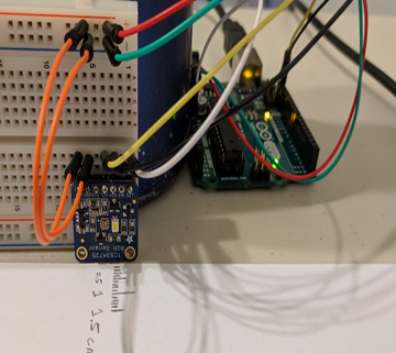
The color sensor was then set up next to a paper with measurement tick marks to measure the distance away from the color sensor (vertical test), and then reconfigured later to measure the distance from either the side of the color sensor (horizontal test), both as shown in the figures below.
Figure 1: Color sensor trade study configuration for vertical distance test.
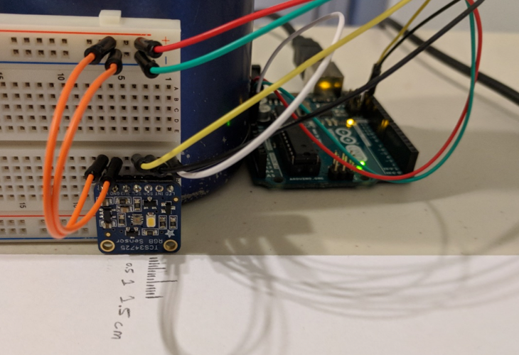
Figure 2: Color sensor trade study configuration for horizontal distance test.
Next, using strips of vinyl tape (electrical tape) I then tested four different color tape strips. To determine the optimal vertical distance away from color sensor, I tested to see where I got a peak measurement and then called that the optimal distance for that color. The color strips used are shown in the figure below with the results for the vertical test following (Table 2: Optimal vertical distance for color strips).
Figure 3: Color strips used in trade study. From left to right: Black, Red, Green, and Blue.
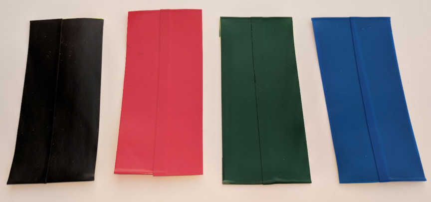
Table 2: Optimal vertical distance for color strips
|
Color-strip color |
Optimal vertical distance |
|
Black |
2 mm |
|
Red |
3 mm |
|
Green |
2.5 mm |
| Blue |
2 mm |
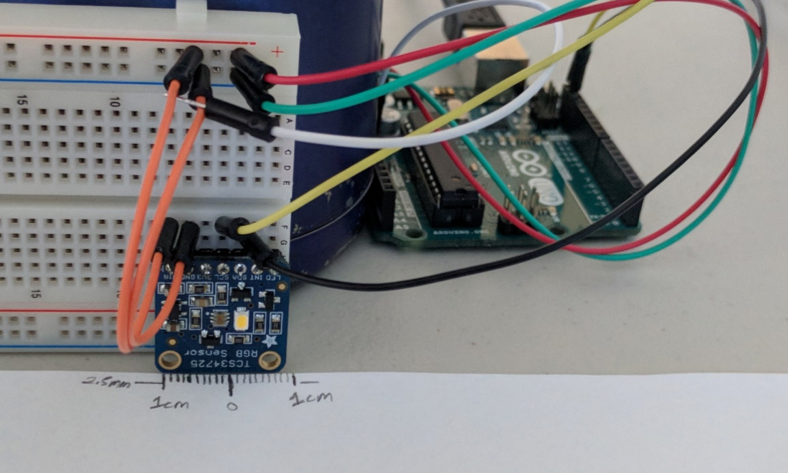
After this test was performed, another test was performed to determine the optimal horizontal distance for the color sensor. This optimal distance will be more subjective, since the color should be far enough away from the sensor to not always be detecting the lines, but close enough to reduce the response time of the robot’s reaction to the line. For this test, I measured two distances for each color. One at the point the colored strip was detected as well as at the point at which the amount of detection significantly spiked. The origin (zero) value was set at the middle of the color sensor. I then performed the test, from the left and the right side of the color sensor, as defined in the figure below. The horizontal test results follow (Table 3: Optimal horizontal distance for color strips).
Figure 4: Test setup to show which side would be the right side of the color sensor vs which is the left.
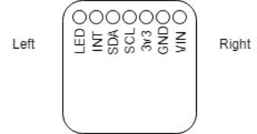
Table 3: Optimal horizontal distance for color strips
| Color-strip color | Detected horizontal distance (Left) | Detected horizontal distance (Right) | Detection spike horizontal distance (Left) | Detection spike horizontal distance (Right) |
| Red | 9 mm | 9 mm | 2 mm | 2.5 mm |
| Green | 1.5 mm | 4 mm | 1 mm | 1 mm |
| Blue | 4 mm | 10 mm | 1 mm | 2.5 mm |
| Black | 3 mm | 3 mm | 0 mm | 0 mm |
It can be noted that the range of detection can vary from color to color, and from left to right due to the location of the color detector on the color sensor. In most cases, the range of detection of the color strip was a small but significant distance further from the right than the range when measuring from the left.
Conclusion
The first result that can be inferred from this trade study is that a vertical distance from the color sensor to the detected color is optimal within a range of 2 – 3 mm. The second result that can be inferred from this trade study is that a horizontal range of 2.5 – 3 mm away (zero being the center of the color sensor) to the detected color will result in consistent readings, with no significant unintentional readings. However, if trying to ensure no color detection when driving along a path, a horizontal range of 9-10 mm might be better desired. Testing with the project specific robot and software will also be an important factor when deciding the layout and placement of the color sensors. This trade study is to be used in supplement with testing to give the engineers a good starting point when designing the color sensor layout.
Source material

Goliath Fall 2017 – Initial Design
After inspecting last year’s final product, I began to redesign the dimensions of the overall body of the tank. While reviewing their SolidWorks’ files, I calculated a maximum possible decrease in width of 8.95 mm. The following changes were made in order to minimize the overall width of the tank and other changes were to […]

Goliath Fall 2017 – Component Testing
This project will be including 4 new peripherals and parts for this iteration of the Goliath. To fulfil the following requirements: Operation Task – Autonomous, L1(13) Operation Task – Recall, L1(14) These parts will be added eventually to the PCB design on the Goliath. The tested components so far are as follows: Color Sensors, LED Matrix, […]

Fall 2017 – 3DoT Chassis Preliminary Design Document & Preliminary Project Plan
By: Elizabeth Nguyen (Project Manager), Melwin Pakpahan (Missions, Systems, and Test Engineer), Yasin Khalil (Electronics & Control Engineer), Zachary de Bruyn (Electronics & Control Engineer), Railan Oviedo (Design & Manufacturing Engineering)
Table of Contents
Preliminary Design Document
Program Objective & Mission Profile
Written by Elizabeth Nguyen
Program Objective
The 3DoT Chassis (the name is expected to be changed) is expected to be 3D-printed as a single assembly, based on the Paperbot. It will be a toy robot with a paper shell that will resemble the mascot of CalState Long Beach (CSULB) Prospector Pete. The robot will be controlled through the arxobot app/control panel. The DC motors (GM6) and the planetary gear system will remain the same as used for Paperbot.
Mission Profile
The 3DoT Chassis will be able to (1) remotely navigate a maze while recording its path (that is determined on the day of demonstration) with its sensor shield and (2) autonomously navigate the same recorded maze path while other autonomous toy robots are present.
Source: Project and Mission Objectives
Requirements
Level One Requirements
Written by Elizabeth Nguyen
Program Requirements
- The 3DoT Chassis shall be completed by Wednesday, December 13, 2017.
- This requirement coincides with the last day of class and this is the projected demonstration date for all toy robots.
- The 3DoT Chassis shall cost no more than $200 as projected by the customer.
- The 3DoT Chassis will be a toy robot.
- This requirement is defined through the customer expectations.
Project Requirements
- The 3DoT Chassis shall use a 3DoT Board (based on Project and Mission Objectives).
- The 3DoT Chassis shall navigate through a maze with remote control through the ArxRobot App or the Arxterra Control Panel (based on Project and Mission Objectives).
- The 3DoT Chassis shall be no larger than 4 x 3.5 x 3 inches.
- These measurements were taken at the widest dimensions of the chassis since it tapers at the bottom.
- The 3DoT Chassis shall be able to memorize a path through the maze that is taught by the user (based on Project and Mission Objectives).
- The 3DoT Chassis shall be able to autonomously travel down the path that was memorized (based on Project and Mission Objectives).
- The 3DoT Chassis should be able to navigate the maze and avoid collisions when multiple robots are in the maze.
- This requirement is not completely defined because the project managers need to determine a way for the robots to avoid each other during their demos.
- The 3DoT Chassis shall have a chassis that is 3D printed.
- This is derived from a customer expectation.
- The total 3D print time of 3DoT Chassis’ parts shall not exceed 6 hours (based on Project and Mission Objectives).
- The main body of the body shall be of one solid piece.
- The 3DoT Chassis shall be easy to assemble.
- The 3DoT Chassis Paper Shell shall resemble the CSULB mascot, Prospector Pete.
- This is a customer expectation.
Level Two Requirements
Written by Melwin Pakpahan
System Requirements
- The 3DoT Chassis shall operate for no less than 20 minutes.
- The 3DoT Chassis shall have a maximum speed of 19.5 centimeters per second.
- The 3DoT Chassis shall have a custom PCB to accommodate for its sensors.
Subsystem Requirements
- The 3DoT Chassis shall be powered by a RCR123A Lithium Polymer battery.
- The 3DoT Chassis shall use a planetary gear system for mobility.
- The 3DoT Chassis shall have a sensor shield on the front.
- The 3DoT Chassis shall have a mechanism for counterweight attached to the shield.
- The 3DoT Chassis shall utilize two GM6 brushed DC motors.
- The 3DoT Chassis shall use a TCS34725 RGB color sensor to navigate the maze.
- The 3DoT Chassis shall use a TCS34725 RGB color sensor to detect and avoid other robots in the maze.
Design Innovation
Written by Elizabeth Nguyen
Caster Wheel
During the creativity exercise, our team determined that the caster wheel required a more innovative solution. There was a need to compensate for the uneven weight distribution caused by the smartphone resting in the front. Previous designs have used a simple castor wheel.
Based on the solutions developed from the suggested techniques (Duncker diagrams, different point of views, forced relationships, etc.), we decided not to implement them. Some were not feasible and there were other tasks that required more attention such as the custom PCB for the SAMB11 and the planetary gear system, which will be addressed.
Gear System
In continuation to the mentioned task that is considered urgent, the implementation planetary gear system is a customer expectation and a potential challenge for the team. It is aesthetically pleasing, which is why the gear system must specifically be planetary; however, this design did not work with a wooden chassis due to friction.
What has changed was allowing COTS gears since they cannot be 3D-printed concisely nor have a strong structure to work. Instead, the focus for the team is to determine an innovative design for the gear system while appearing planetary.
The challenge also discovered was for a true planetary gear system, torque comes from the middle gear, which then rotates the smaller planetary gears, allowing the wheel to turn. However, with the current chassis design, torque comes from the top gear, which will turn the rest of the gears.
Gear studies will be performed.
Custom PCB to replace 3DoT Board
A challenge provided for the team is to design and assemble a custom PCB that will replace the 3DoT Board that is used to power and control the robot. The ATMega32U4 will be replaced with the SAMB11 and there will be an implementation of the IFA on the SAMB11 Board as discussed below.
ATMega32U4 replaced with SAMB11
The current 3DoT Board v454 has components that are incorporated separately on the PCB as opposed to the SAMB11 where those components are built-in [1]. Benefits from replacing the chip would include less power for the SAMB11 because less components would be required ont he PCB and would not require the HM10 to be implemented onto the board because bluetooth is also integrated.
Implementation of IFA on SAMB11 board
Because of the replacement of the ATMetga32U4 with the SAMB11, an antenna is required for communication purposes between the users (our team) and the board itself. An Inverted-F Antenna was chosen and will communicate with the board using 2.4 GHz.
References:
Systems/Subsystem Design
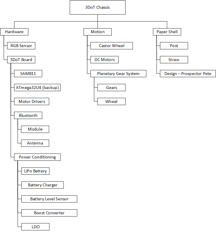
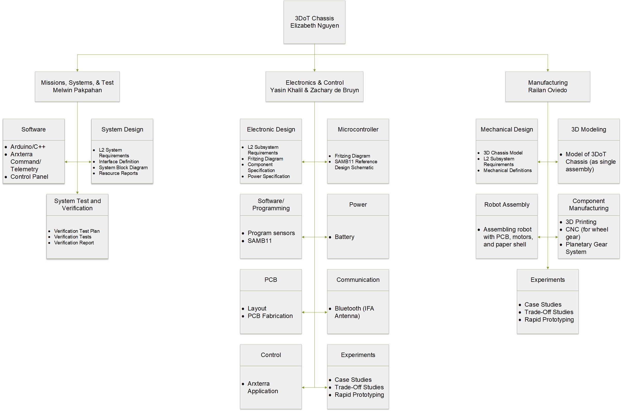
Product Breakdown Structure
Created by Melwin Pakpahan
Electronic System Design
System Block Diagrams
Created by Zachary de Bruyn
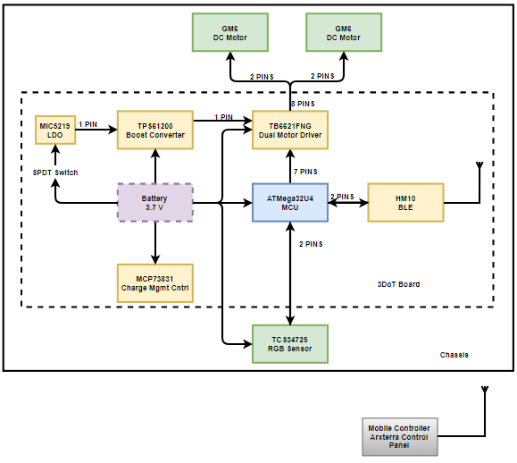
System Block Diagram for 3DoT Board
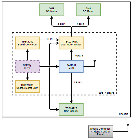
System Block Diagram for SAMB11 Board
Interface Definitions
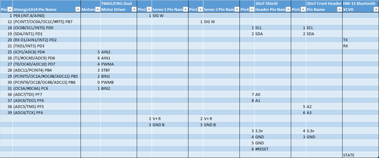
3DoT Interface Definition
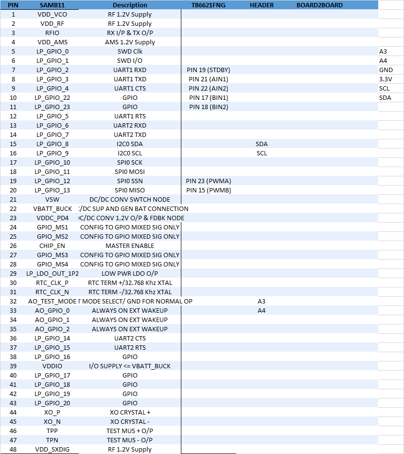
SAMB11 Interface Definition
Mechanical Design
Written by Railan Oviedo
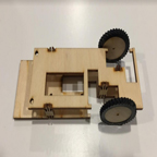
For this version of the 3DoT Chassis, the customer’s biggest requirement is to have it 3D-printed as a singular piece. This varies from the previous iterations, as they had each required an assembly of the chassis first. In order to realize this, I will have to adjust the previously made 3D modeled parts and combine them in such a way that the entire chassis can printed at once.
To avoid long print times—and thus a higher chance of an error while printing—the chassis’ front and back will have to be perforated so as to avoid printing unnecessary space. To comply with the boundaries made by the Prospector Pete paper structure, the Chassis size will not exceed measurements of 4 x 3.5 x 3 inches. Furthermore, the primary method of movement will be realized through the use of a planetary gear system. The inner workings of the Chassis will remain relatively the same from the previous plastic design. That is, there will be grooves to hold in the 2 DC motors and the 3DoT board, which will have a battery and circuitry for the robot placed onto it. The final aspect of the 3DoT Chassis will involve a shield placed in the front in order to allow for placement of sensors and navigation along with a castor wheel for counter-balance purposes. This shield will also serve as a stand for a phone that can be placed on the chassis.
The following images show what the general shape of the chassis looks like from a diagonal view, side view, and front view:
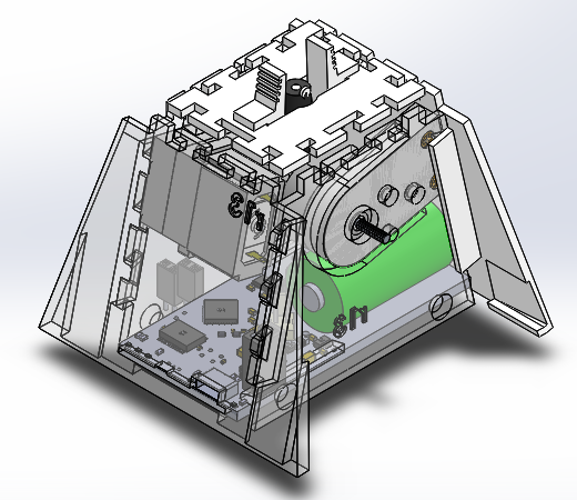
3DoT Chassis Diagonal View
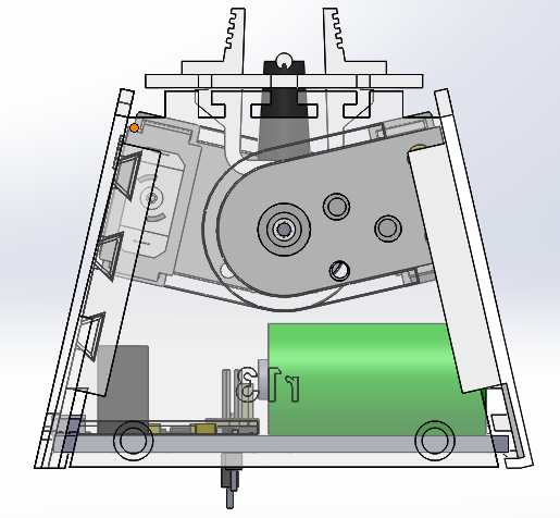
3DoT Chassis Side View
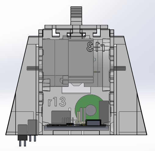
3DoT Chassis Front View
Design and Unique Task Descriptions
Manufacturing
3D Printed Chassis
Written by Railan Oviedo
As previously stated, a singular design of the chassis can be modeled through referencing the previous models made by prior teams that worked on the 3DoT. The major goal for the completed 3D chassis design is to be able to be printed in less than 6 hours, so as to ensure that the printed chassis will not experience structural failures.
Because this version cannot be disassembled, the issue of placing the motors in comes into play. To circumvent this problem, I am planning on creating rectangular holes on the front and back of the chassis in order to easily insert the motors onto their slots. This solution would not only resolve the motor placement issue, but also reduce the necessary printing time for the chassis.
In regards to the planetary gear system, it is imperative to make sure the gears can fit within the primary wheel’s 5.5 cm diameter. The current plan is to create a triangular gear train with 3 large gears that are each attached to a smaller gear that serves as the center focal point. This setup should result in little to no loss of rpm between the large gears, as they are the ones that will be connected to the primary wheel.
An expected completion date for a 3D model design is October 25, 2017.
Electronics & Control
Inverted-F Antenna
Written by Zachary de Bruyn
The 3DoT Chassis team will be implementing two varieties of “3DoT” boards. One board will consist of the heritage 3DoT ver. 4-54 board which utilizes the ATMega32U4. In order for the heritage 3DoT to communicate with peripheral devices, an additional component, the HM10, is needed to provide a 2.4GHz link between a transmitter (XMT) and the HM10. The second board, however, utilizes a SAMB11 SoC. Within the SAMB11 is the BLE device necessary to communicate at 2.4GHz, but requires the design and implementation of an antenna external to the SAMB11.
Implementation of an antenna design is dependent on the frequency at which it is to receive. Therefore, in order to implement a PCB antenna which utilizes the 2.4GHz, which bluetooth is dependent on, we are limited to only a couple of antenna varieties [1]. In short, the Inverted-F Antenna (IFA) was chosen for a couple of reasons: 1) It is similar to the design of the antenna on the HM10, which is a proven concept; 2) the IFA is isotropic allowing for reception from a wide range of three-dimensional locations, and 3) it allows for 2.4GHz reception. The expected completion date is November 1, 2017.
References:
[1] http://www.ti.com/lit/an/swra161b/swra161b.pdf
[2] http://www.ti.com/lit/an/swru120c/swru120c.pdf
Color Sensors (TCS34725)
Written by Zachary de Bruyn
It is the goal of the 3DoT team to implement the Light-to-Digital Converted (RGB Sensor) in order to read the different colors that are imposed on the maze/roadway in order to navigate the maze autonomously. The benefit of using the color sensor is that it will allow the toy robot to use the color values it evaluates to maintain the direction on the maze. We can then implement a controlled response that will allow the toy robot to correct its direction based on interference from other undesirable colors. There is an expected completion date of November 15, 2017.
References:
[1] https://cdn-shop.adafruit.com/datasheets/TCS34725.pdf
SAMB11
Written by Yasin Khalil
The SAMB11 will be implemented in custom PCB to replace the heritage 3DoT ver. 454 board that utilizes an ATMega32U4.
The SAMB11 will provide all of the base features as the ATMega32U4 in the original 3DoT board. These features include a dual H-Bridge, sensors, power management (battery, usb, etc.), servo’s, and DC motors. There will also be correlating headers to that of the 3DoT to allow for seamless integration with past projects.
An expected completion date will be November 15th, 2017.
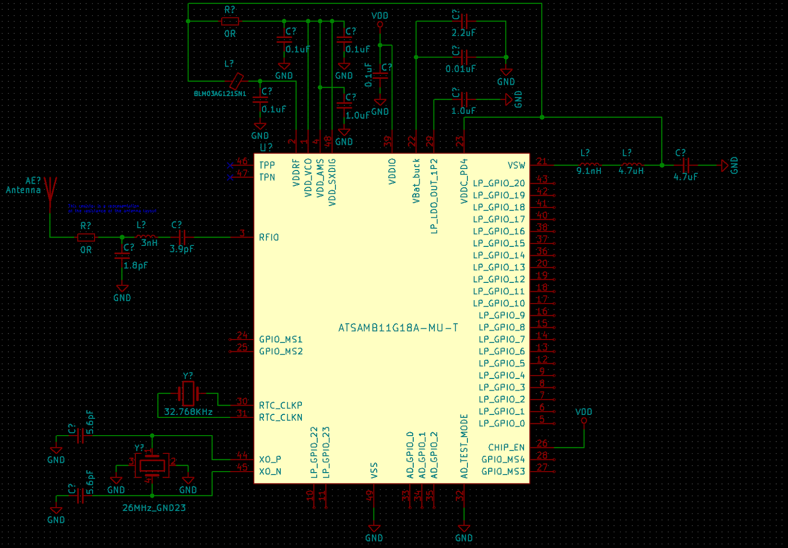
SAMB11 Reference Design Schematic
Preliminary Project Plan
Work Breakdown Structure
Created by Elizabeth Nguyen
Project Schedule
Created by Elizabeth Nguyen
Top Level Schedule
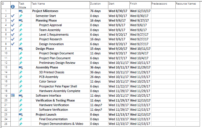
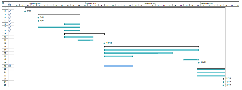
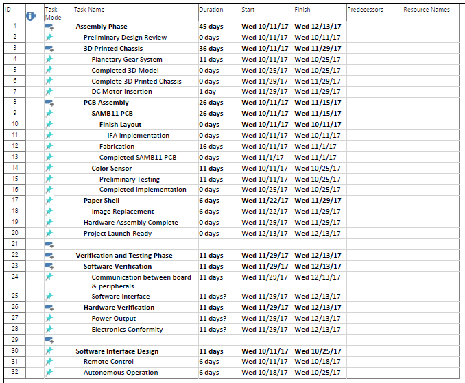
System/Subsystem Level Tasks

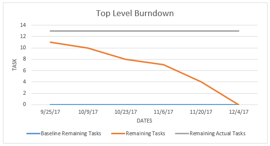
Project Burndown
The current graph shows a burndown from a top level view; however, it is difficult to ascertain the ideal burndown. It will be updated with the correct dates as well.
System Resource Reports
Created by Melwin Pakpahan
Project Cost Estimates
Written by Elizabeth Nguyen
A budget of $200.00 was projected by the customer. It is difficult to ascertain an estimated budget due to variances in services such as 3D printing and PCB board assembly. However, at least 50% of the budget is estimated to go towards physical parts and the rest of the budget will be allocated towards services.

Goliath Fall 2017 – Preliminary Project Plan
This is the Work Breakdown Structure (WBS) for this project. The diagram breaks the tasks among each of the three engineering areas. Then further lists specific tasks for each part of the project. In this way, the document shows clearly what each person’s responsibilities are. These assignments were based on the system block diagram created by the Mission […]
Goliath Fall 2017 – Preliminary Design Document
The Goliath tank will participate in a set of events taking place on a maze with an overlaid grid matrix. The first event will be navigating the maze first under remote control then autonomously repeating the same driven route. A second event will involve other robots located within the same maze space. In this event, […]

Fall 2017 BiPed: Preliminary Design Document
By:
Piyush Jain (Project Manager)
Zachary Bruyn & Yasin Khalil (Electronics & Controls)
Natalie Arevalo (Manufacturing)
Melwin Pakpahan (Missions, Systems, & Test)
Table of Contents
Program Objective
By: Piyush Jain (Project Manager)
The objective of Project BiPed is to design and manufacture a miniature bipedal robot. The BiPed shall incorporate a Theo Jansen leg design, use a single DC motor and mini servo for walking and turning, and shall use a similar joint mechanism as the 2017 Spring Velociraptor [1].
The model of the BiPed shall use the same principle mechanics as Theo Jansen models, with the design inspired by the 2017 Spring Velociraptor. The difference between the design shall be:
- The head shall be removed and the tail replaced altogether with a different system of allocating the mass to retain a proper center of mass.
- Replace clunky hip design with something more compact which has a smaller turning radius.
Mission Profile
The mission of Project BiPed is to design the BiPed to navigate a predesigned maze [1]. The BiPed shall be able to navigate the maze with user input from the Arxterra App/Control Panel. The BiPed will be able to memorize the user-defined path and will be able to navigate it autonomously. In addition, the BiPed will acknowledge other robots while traversing the maze and avoid collisions.
References:
[1] http://web.csulb.edu/~hill/ee444/2%20The%20Mission.pdf
Requirements and Verifications
Program Level 1 Requirements
By: Piyush Jain (Project Manager)
L1-1: The Biped shall be finished by Wednesday, December 13, 2017 [1]
L1-2: The Biped shall not exceed a budget limit of $250.00
L1-3: The Biped Shall be a toy robot.
Project Level 1 Requirements
By: Piyush Jain (Project Manager)
L1-4: The BiPed shall navigate the maze with user-defined inputs.[2]
L1-5: The BiPed shall memorize said user-defined path and navigate it autonomously.
L1-6: The BiPed shall navigate the maze in seven minutes or less.
L1-7: The BiPed shall navigate the maze without colliding into other robots.
L1-8: The BiPed will be controlled by a 3DoT board.
L1-9: The BiPed will be able to walk on cloth, linoleum, and paper.
L1-10: All electronic components shall be able to be disassembled and reassembled within 20 minutes.[3]
L1-11: All 3D printed robot components shall be printed in less than 6 hours, with no single print session taking longer than 2 hours.[3]
References:
[1] http://web.csulb.edu/gobeach/depts/enrollment/dates/registration.html
[2] http://web.csulb.edu/~hill/ee444/2%20The%20Mission.pdf
[3] http://web.csulb.edu/~hill/ee400d/Project%20and%20Mission%20Objectives.pdf
System/Subsystem: Level 2 Requirements
By: Melwin Pakpahan (Missions, Systems, & Test)
L2-1: Operate using the Arxterra Android/iPhone application. This includes navigating the maze, with and without user input, as well as turning and walking. L1-4
L2-2: Have Bluetooth communication which will sync with the Arxterra Android/iPhone application L1-3
L2-3: Be integrated with all the appropriate libraries to communicate with all electronic devices. L1-8
L2-4: Use a gyroscope/accelerometer to help navigate its way through the maze. L1-4
L2-5: Use a proximity sensor to detect and avoid other robots in the maze. L1-7
L2-6: Design the BiPed’s feet size to be approximately 3″ by 2.5″. L1-3
L2-7: Design the BiPed’s hip size to not exceed 3″. L1-3
L2-8: Design the BiPed’s center of mass shifting system to not exceed 5″ in length and width. L1-3
L2-9: Choose a motor which will provide enough torque to support the weight of the BiPed. L1-6
L2-10: Design the BiPed to be less than 1.5 pounds. L1-6
L2-11: Be powered by one RCR123A Lithium Polymer Battery which will operate for a minimum of 10 minutes before recharge.
L2-13: Utilize one mini servo for turning and one for the mass shifting mechanism. L1-6
L2-14: Be wired in a manner which is professional and shall not interfere with when navigating the maze. L1-6
L2-15: Have two leaf springs on each foot, for stability and flexibility of the feet. [1] L1-9
Design Innovation
By: Piyush Jain (Project Manager)
Working from the previous semester’s built BiPed chassis, the team came up with potential problems we might encounter. With respect to the customer’s demands, our main problems were turning the Biped, while maintaining a small turning radius, and the static walk, with the feet in close proximity, all while maintaining a proper balance for the BiPed. We decided we would focus on turning the BiPed as that is the biggest challenge. From our creativity exercise, we surmised different methods of turning including : having a 3″ or less turning gears for the hips, having a joint system similar to humans, and removing the turning gear all together and attaching wheels to legs to drive the BiPed through the maze. The first two methods were thought up during the brainstorming approach, while the last one was thought up during the attritube listing. After going over all our options, we decided to design a turning gear which will be less an 3″ because that will give us the greatest control in how the BiPed turns.
System/Subsystem Design
Product Breakdown Structure
By: Piyush Jain ( Project Manager)
Power
The Biped shall be powered by a singular portable CR123A Lithium Polymer Battery. The battery shall power the 3DoT board, 1 DC Motors, 1 Servos, I2C, and the Accelerometer/Gyroscope.
Actuator
The actuators for the BiPed are 1 DC Motors and Servos. The DC Motor will control the leg movement for walking, while the servo will control the turning mechanism.
Communication
The Software for the BiPed will be in C++ and written in Arduino sketch. The code shall control the motor functions and communicate with the Bluetooth module. The module will be controlled via the Arxterra control panel, synched to an Android or iPhone.
Manufacturing
With the chassis prebuilt, we will focus on creating an optimal design for the hip and feet. The hip shall be able to turn with a small turning radius, to fit within the parameters of the maze, while the feet shall be designed to stabilize the structure. In addition, the center-of-mass distribution shall be manufactured as to maintain a center of balance when walking and turning.
PCB
Our design will incorporate two PCB boards. The first will be the 3DoT board, provided by Professor Hill, which will contain the microcontroller and shall control the servos and motors. The second will be the custom PCB board which shall control everything else.
Electronic System Design
System Block Diagram
By: Zachary Bruyn (Electronics & Control)

The Microcontroller has inputs of the battery and input sensors. The battery shall power the BiPed and the Input Sensors; accelerometer/gyroscope and proximity sensor help to navigate the BiPed thru the maze. The Actuators; DC motors and servos help to physically move the BiPed. The communication device includes the Arxterra application, control panel, Android/iPhone, and Bluetooth device give the user the ability to control the BiPed.
Interface Definition
By: Melwin Pakpahan (Mission, Systems, and Test)
The interface definition shown below defines the pins of the ATmega32U4. The microcontroller has a modest selection of programmable pins to configure. In the future, trade-off studies will be conducted to determine which resources would best suit components and how to configure them accordingly [1]

Reference:
[1] https://www.arduino.cc/en/Hacking/PinMapping32u4
Mechanical Design
By: Natalie Arevalo (Manufacturing)
The overall design of this semester’s BiPed project can be broken down into four major sections: feet, legs, hips, and center-of-mass shifting mechanism.
The project as a whole can be seen as an iteration of the Spring 2017 Velociraptor project or modification of the Velociraptor project into a BiPed. As a result, the design of the BiPed will be kept as top-heavy however the head-tail component of the velociraptor will be eliminated. Although the body of the BiPed will be kept heavy to keep its moment of inertia small, the weight will be kept confined to the center-of-mass shifting mechanism as well as the servos and motors. In addition, stability in the legs and feet will be increased by using different materials as that of the previous project for the feet as well as by making the feet bigger to better distribute the weight along to using different springs.
Feet
The size of the feet will be increased so that the weight of the top-heavy robot can be better distributed as it’s walking. Additionally, the shape of the feet was also modified to minimize the amount of material to be used in the manufacturing. Since most of the weight of the robot will be exerted on the corners of the feet, just like how the weight of humans is placed on the toes and heels of the foot, the shape was kept with four major corners.
Back of envelope design
A trade-off study in conjunction with a simulation in SolidWorks will be later conducted to determine which design will work the best for the BiPed. Furthermore, the feet will be incorporated into the BiPed so that they can hinge as the robot takes a step. To increase the stability of the feet and therefore the ankle part of the robot, a leaf spring will be used in place of a traditional spring. The leaf spring will provide the better stability while still maintaining enough flexibility for the foot to flex at every step taken.
Legs
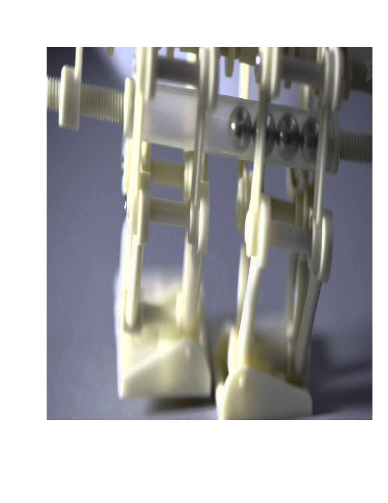
The leg design from the Spring 2017 Velociraptor project will be kept the same. The design used previously is the linkage system found in the Theo Jansen Walking Biped. The linkage system already mimics the kinetics behind walking. Furthermore, the design eliminates the need for taking into account the hinge movement of the knee since the leg rotates at the hip and creates that movement on its own.

Leg Design Model from Wiki [1]
Reference:
[1] https://en.wikipedia.org/wiki/Jansen%27s_linkage#/media/File:Jansen%27s_Linkage.svg
Hips
The hips as a whole are being made smaller in width so as to make them have a tighter look them. This is going to be accomplished by making gears in the hips that allowed the velociraptor to turn have a smaller radius. Additionally, the space between the universal joint and the rotating disk of the hip/leg will be made much smaller. With these two modifications, the hips will be made smaller in diameter which will decrease the distance of rotation during turning as well as decrease the time it takes the robot to turn and therefore navigate the maze. A quick Solidworks model is provided below based on preliminary talks on the optimal design.
Center-Of-Mass Shifting Mechanism
In order to modify the velociraptor design into a BiPed, the head-tail component was completely eliminated. As a result, a center-of-mass shifting mechanism had to be created in order to shift the center of gravity of the BiPed as it is turning so that the toy will not fall over during this motion. The inspiration for the mechanism came once again from the Theo Jansen Walking Biped. The weight shifting mechanism used in this robot can be seen here:
Essentially, this mechanism would be implemented in an automated version instead of a purely mechanical way. A weight will be placed as part of the body of the robot that will be slowly shifted by a motor to the opposite side of the pivot point of the BiPed as its turning. The modeling and simulation of this mechanism will be done in the future.
Design & Unique Task Description
By: Piyush Jain (Project Manager)
The BiPed shall incorporate a single 3.7v battery which shall power the BiPed through the three maze trials. The battery will be able to be recharged in between the trials. The BiPed shall use one mini servo and one DC motor to help turn and perform a static walk. The turning mechanism shall employ a small turning radius. The static walk shall ensure that the feet are kept in close proximity.
BiPed Tasks
- Conduct trade-off study to choose the optimal DC motor and servo for given parameters. – October 11th
- Create the fritzing diagram to test the breadboard. – October 10th
- From the fritzing diagram create PCB on Eagle CAD. – October 16th
- Using Arduino IDE to create control algorithm for the servo and DC motor – November 29th
- Design Center of Mass part to maintain balance during walking, turning and stopping. – October 29th
- Design lightweight and efficient models for the legs and hip. – October 15th
- Configure proximity sensor to detect other robots while traversing the maze. – October 6th
- Create Interface Diagram which is compatible with both 3DoT chassis and BiPed. – October 11th
Work BreakDown Structure
By: Piyush Jain ( Project Manager)
The Work Breakdown Structure displays in an easy to read manner for the tasks which need to be completed by the respected division engineers. It details the kind of work which has to be done, moving forward, in order to have a successful BiPed by December 13, 2017. The tasks were derived from the Lv 1 requirements agreed upon by the customer.

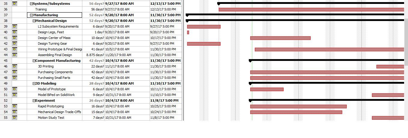
Project Schedule
By: Piyush Jain (Project Manager)
The Project Schedule details the project timeline from a Top-Level/Subsystem Level perspective. The Top Level consists of four main sections; Planning Phase, Design Phase, Assembly Phase, and Project Launch. These four sections help to guide the project towards mission success by breaking the work down into realizable goals.
The System/Subsystem Level was designed to complement the Work BreakDown Structure. It details the specific work which needs to be done by each engineer in their specific division. It allots specific time to each task such that the project will be completed by December 13, 2017. It is broken down into the Manufacturing, MST, and E&C division.
Top Level Schedule

System/Subsystem Level Tasks


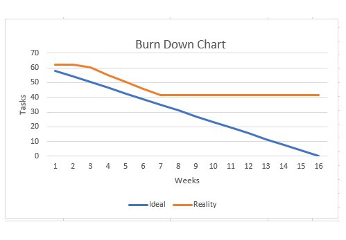
Burn Down
By: Piyush Jain (Project Manager)
The Burn Down Schedule shows the amount of work needed to be completed in order for the mission to be a success. The blue linear line shows the ideal schedule for the amount of work per week. The orange line indicates the actual work to be done. As shown, the work increases in loads as the semester progresses.
System Resource Reports
By: Melwin Pakpahan (Missions, Systems, & Test)
The Lv 2 requirement for the BiPed is to be under 850 grams or roughly 1.5 pounds. This was selected so the BiPed would be able to traverse the maze in a timely manner. A rough mass report was generated to guide us to hit our Lv 2 requirement. According to this report, we are well under the 850 grams. Our biggest item of uncertainty is the frame of the BiPed. It is estimated to come in at 300 grams, which is 200 grams less than the previous semesters’ design.

A preliminary power report is provided below. The power report is missing much of the Electronic & Control engineering work because we had many problems with the engineer. By October 25th, 2017 we shall have an updated power report.

Project Cost Estimate
By: Piyush Jain (Project Manager)
The main program requirement for this BiPed is that it shall not exceed $250.00. A project budget cost was formulated with this requirement in mind. As seen by the image below, we are well below the limit of $250.00. We are able to reduce the cost of this project by obtaining several times from Hill, including the DC motor and mini servo. Also, the sensors decided will be of low cost and optimal performance. The main cost of the project will be the frame of the BiPed because we decided to incorporate a more compact, yet sturdy design. The item of most concern is the custom PCB. Even with a $10 estimate, based on a quick research, we will need to conduct a more in-depth research as to which companies can provide us a high quality, low-cost single board.

ModWheels Preliminary Design Document
By: Lucas Gutierrez (Project Manager)
ModWheels Team Members:
Project Manager: Lucas Gutierrez
Mission, Systems, and Test Engineer: Andrew Yi
Electronics and Control Engineer: Matt Shellhammer
Design and Manufacturing Engineer: Adan Rodriguez
Table of Contents
Program Objectives / Mission Profile
By: Lucas Gutierrez (Project Manager)
Objective
ModWheels is a toy car that will navigate a multi-colored 2D maze using the Arxterra App for remote control. The initial phase consists of having the toy car navigate the maze with user input. ModWheels will then memorize the route taken during the initial phase and will be able to autonomously navigate the maze for the second phase. Another rule of the maze will be to detect other robots and avoid collision. These are the objectives stated by the customer.
ModWheels toy car is a new project within The Robot Company. The modular design comes from the changeable paper overlay, allowing the user to swap out to their preferred design. Color sensors will be used to detect the walls of the maze, keeping the toy car within the confines of the maze hallways. To avoid collision, ultrasonic sensors will be used to detect the other robots within the maze. Infrared sensors will detect the black lines in the maze indicating intersections.
Requirements
By: Andrew Yi (Mission, Systems, and Test Engineer)
Program Level 1 Requirements
L1-1: ModWheels shall be completed by Wednesday, December 13th, 2017.
L1-2: ModWheels will be a toy robot.
L1-3: ModWheels shall cost no more than $200.
Project Level 1 Requirements
L1-4: ModWheels will use a 3DoT board.
L1-5: ModWheels shall use a peripheral custom PCB connected to 3DoT board.
L1-6: ModWheels will be able to be controlled through the ArxRobot App or Arxterra Control Panel.
L1-7: ModWheels shall navigate a multi-colored 2D maze.
L1-8: ModWheels shall stop when another robot has been detected within a 1.5 foot radius ahead.
L1-9: ModWheels should be able to avoid collisions with other robots operating within the maze.
L1-10: ModWheels shall provide video feedback through a smartphone placed on the toy car.
L1-11: ModWheels shall weigh no more than 500 grams.
L1-12: ModWheels shall be able to memorize a path through the maze taught by the user.
L1-13: ModWheels should be able to travel down the memorized path autonomously.
L1-14: ModWheels should be able to adopt an electronic differential with dual rear motors.
L1-15: ModWheels should be able to adopt a slip differential with dual rear motors.
System & Subsystem Level 2 Requirements
L2-1: ModWheels will have a 3DoT board mounted on the chassis of the ModWheels toy car, as defined by L1-4.
L2-2: ModWheels shall use 2 color sensors to detect the walls within the maze so that it can keep itself within the confines of the hallways, as defined by L1-7.
L2-3: ModWheels shall use the ultrasonic sensors to detect other objects 1.5 feet in front of the toy car, as defined by L1-8.
L2-4: ModWheels will be controllable through Arxterra App using the HM-11 Bluetooth module on the 3DoT board. The Arxterra App has a graphical user interface (GUI) that allows control of the toy robot, as defined by L1-6.
L2-5: ModWheels should have an area for a smartphone to be placed onto it. The phone should have a periscope attachment on its camera and will provide live feed video via the Arxterra App, as defined by L1-10.
L2-6: ModWheels shall navigate a maze autonomously after it has cleared the maze with user input. The autonomous route shall follow the original route without user input, as defined by L1-12.
L2-7: ModWheels will be a remote controllable toy car with a paper shell overlay. The paper shell overlay gives the ModWheels its customizability, as defined by L1-2.
L2-8: ModWheels should use the ultrasonic sensor to reroute themselves if another robot is approaching it head on. When oncoming traffic is detected, ModWheels should direct itself closer towards a wall to allow the oncoming robot to pass, as defined by L1-9.
L2-9: ModWheels shall use a custom PCB to control the ultrasonic, infrared, and color sensors. This PCB shall be connected to the 3DoT board aboard the chassis, as defined by L1-5.
L2-10: ModWheels shall use 2 infrared (IR) sensors to detect the black lines in the maze that indicate intersections, as defined by L1-7.
L2-11: ModWheels shall stop when another robot is detected to be 1.5 feet in front of the toy car, as defined by L1-8.
L2-12: ModWheels shall cease all motor functions when another robot is detected 1.5 feet in front of it. It shall resume resume normal operations after the robot has left the detection area, as defined by L1-8.
Source Material:
Design Innovation
By: Matt Shellhammer (Electronics and Control Engineer)
Creative Design
- Rules of the maze.
- Navigating the maze with other robots traveling through at the same time across many various paths has proved to be a very elaborate ConOp. One possible solution for this problem, discussed during the forced relationship and dunker diagram activities, is creating a specific rules of the maze that will be followed by all robots in the maze to ensure that no robots collide. To establish the rules of the maze our project manager is speaking with the other project managers and trying to agree upon a standardized set of rules for the maze.
- Able to download additional maze maps quickly.
- This solution came about from the forced relationships technique trying to force a bookcase onto the ModWheels car. This brings up the task of being able to remotely drive through the maze using the Arxterra app and then being able to then repeat that path autonomously. Doing so, after changing the maze in ModWheels memory it can quickly and easily memorize and follow new mazes and routes.
- Sense other robots within the maze to avoid collisions
- Yet again, during the dunker diagram activity, one of our big concerns was navigating the maze while other robots are also within the maze. Another technique for avoiding other robots within the maze was to add a sensor, such as an ultrasonic sensor, to use to detect and avoid obstacles within the maze. We will be using an ultrasonic sensor on ModWheels to achieve this awareness.
- Making turns within the maze
- In a maze, making accurate turns is something of great importance, since a poor turn can cause you to veer off the desired path. Two different possible approaches to this problem were discussed. The first approach discussed was to design a car that has wheels that can rotate 360 degrees allowing the car to never have to turn, the wheels will rotate and the car will stay in place. Since the ModWheels chassis relatively fixed, this approach isn’t really viable, however we did discuss another more possible approach, using encoders. Both of these approaches were a result of the attributes listing creative solutions activity.
- Navigating within the maze
- To navigate throughout the maze there must be certain sensory devices on the vehicle that allow it to be aware of its surroundings. The solutions developed to help ModWheels be aware of its surroundings is IR and/or color sensors to help detect the rooms of the maze. These sensors could also later be used as an additional tool to gather information when making a turn within the maze.
Source Material:
Systems/Subsystem Design
By: Andrew Yi (Mission, Systems, and Test Engineer), Matt Shellhammer (Electronics and Control Engineer), and Lucas Gutierrez (Project Manager)
Product Breakdown Structure
By: Andrew Yi (Mission, Systems, and Test Engineer)

The ModWheels car is broken into 6 sections for the Product Breakdown Structure (PBS). The visuals consist of a smartphone with periscope attachment feeding live video back to the user. The motors, wheels, and servo are the main parts of the mobility of the toy car. Bluetooth and the Arxterra app allow for mobile control of the toy car. The color and ultrasonic sensors will aid in detecting walls (color) and robots (ultrasonic). The paper overlay and 3D printed plastic allow for customization of the ModWheels toy car. A singular 3.6V RCR123A battery will power the ModWheels car and its peripherals.
Electronic System Design
System Block Diagram
By: Andrew Yi (Mission, Systems, and Test Engineer)

The System Block Diagram (SBD) gives a visual of how the different components of a system are connected. The motor drive on the 3DoT will power the dual RWD motor, which in turn controls the rear wheels. The color sensors on the custom PCB assist in wall detection (in maze) and in detecting other robots within the maze. A periscope will be attached onto the camera of a smart phone and placed on the ModWheels car. This will give live feed video back to the user. The servo allows for turning of the front wheel and controls the steering of the toy car.
Interface Definition
By: Matt Shellhammer (Electronics and Control Engineer)
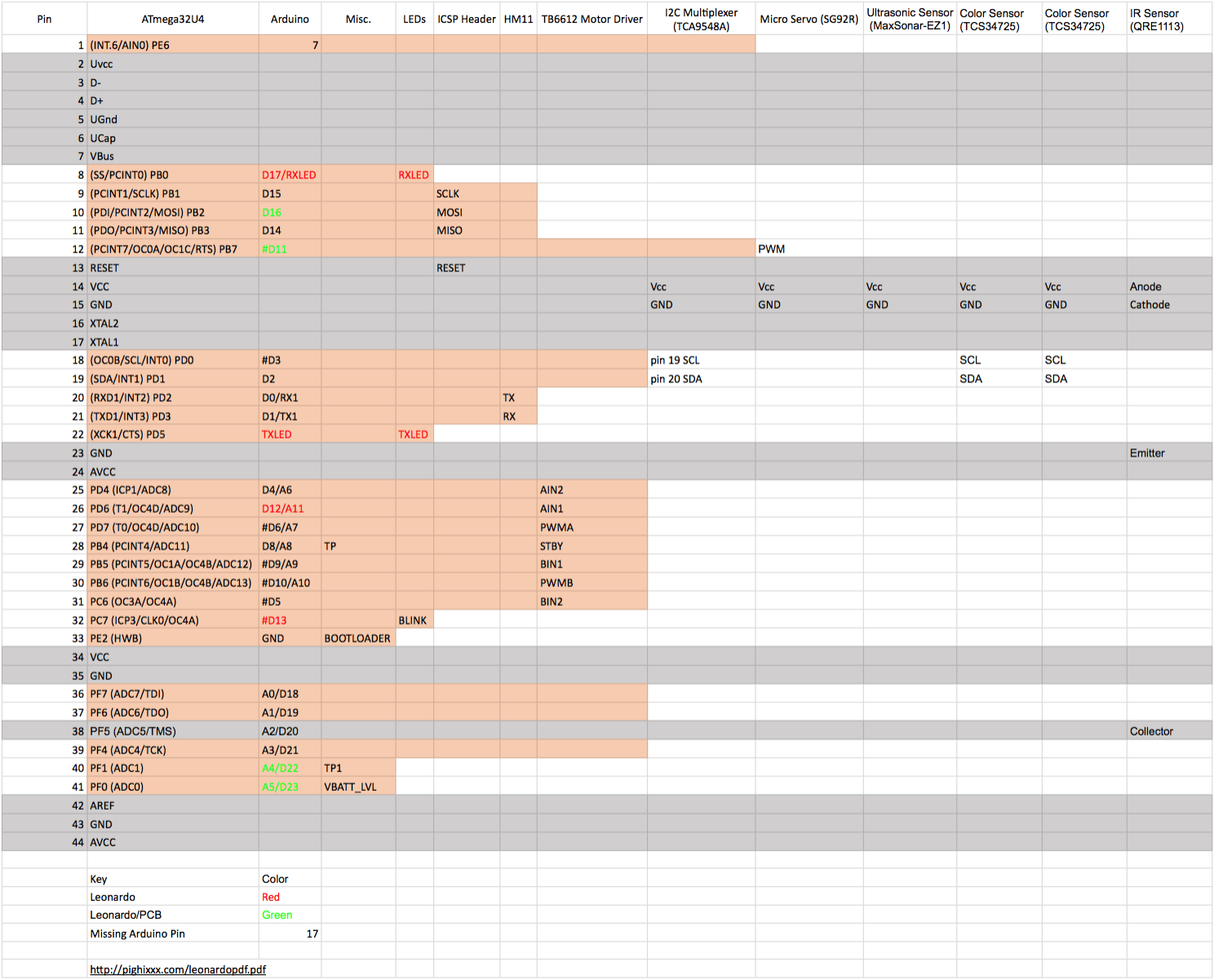
To know how all of the external components will interface with the 3DoT board the table has been created to know what connections will be required for each of the individual components. This table can then be used to configure the interface matrix between the 3DoT board and the external components.
Mechanical Design
By: Lucas Gutierrez (Project Manager)
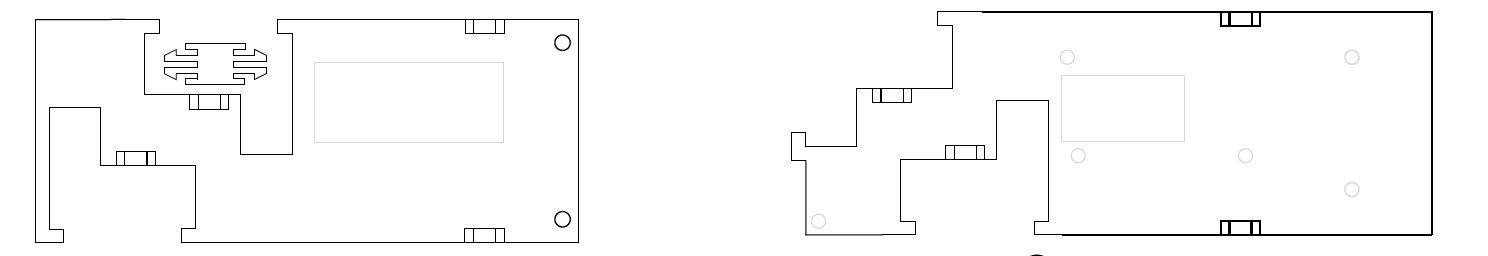
This Illustrator file shows the first and foundational model to which ModWheels will develop from. This two dimensional vector file is converted to a .dxf file which is readable by Laserworks, a software interface for the Kaitian laser cutting and engraving machine. Once correct settings in Laserworks are enabled, optimal settings for a certain material, the laser cutting and engraving machine cuts and engraves the material (1/8″ 3-ply birch) from which the car can be assembled.
Design and Unique Task Description
By: Matt Shellhammer (Electronics and Control Engineer)
Electronics and Control
- Trade study of various ultrasonic sensors to determine the best fit for our application.
- Trade study to determine if we tune two separate motors to drive straight at 40 percent power, will they continue on that same path when the power to the motors is increased (e.g. 50 percent, 60 percent, 70 percent, etc.).
- Trade study to test maze configurations (1 to 4 cells) using the 3DoT board, and determine the optimal hedge distance and ideal sensor layout.
- Perform a power system analysis to lay out a power budget for our system (determine current draw for all of the components).
- Determine configuration to be used for I2C communications.
- Create Fritzing diagram for custom PCB.
- Customize Arxterra app / dashboard for specific ModWheels applications.
- Breadboard testing of turning mechanism & sensors.
- Determine how sensors will be used for navigating the maze (e.g. line follower, wall follower, room detection).
- Develop software for: room detection, path memorization, autonomous navigation of the maze, etc.
Manufacturing
- Create Solidworks model of ModWheels chassis from the current 2D model of the ModWheels chassis.
- Design method for mounting sandblaster front wheels chassis and servo onto the current ModWheels chassis.
- Design method for mounting PCB and sensors onto the current ModWheels chassis.
- Design cell-phone mount for ModWheels chassis.
Preliminary Plan
By: Lucas Gutierrez (Project Manager)
ModWheels Team Members:
Project Manager: Lucas Gutierrez
Mission, Systems, and Test Engineer: Andrew Yi
Electronics and Control Engineer: Matt Shellhammer
- Fritzing Diagram
- Electronic Motor Study
- Printed Circuit Board (PCB) Design & Test
- 3DoT Firmware
Design and Manufacturing Engineer: Adan Rodriguez
- Eagle CAD for PCB layout
- SolidWorks for ModWheels 3D model
- Manufacture Chassis, 3D printed parts, and laser cut parts
- Assemble ModWheels
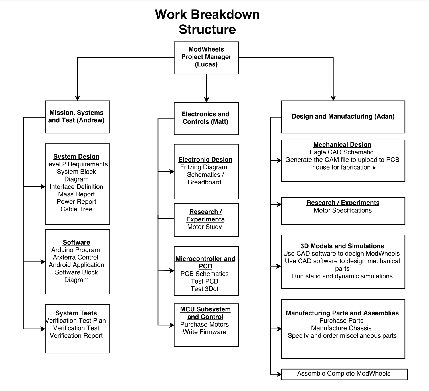
Work Breakdown Structure
By:
Project Schedule
By: Lucas Gutierrez (Project Manager)
Top Level Schedule
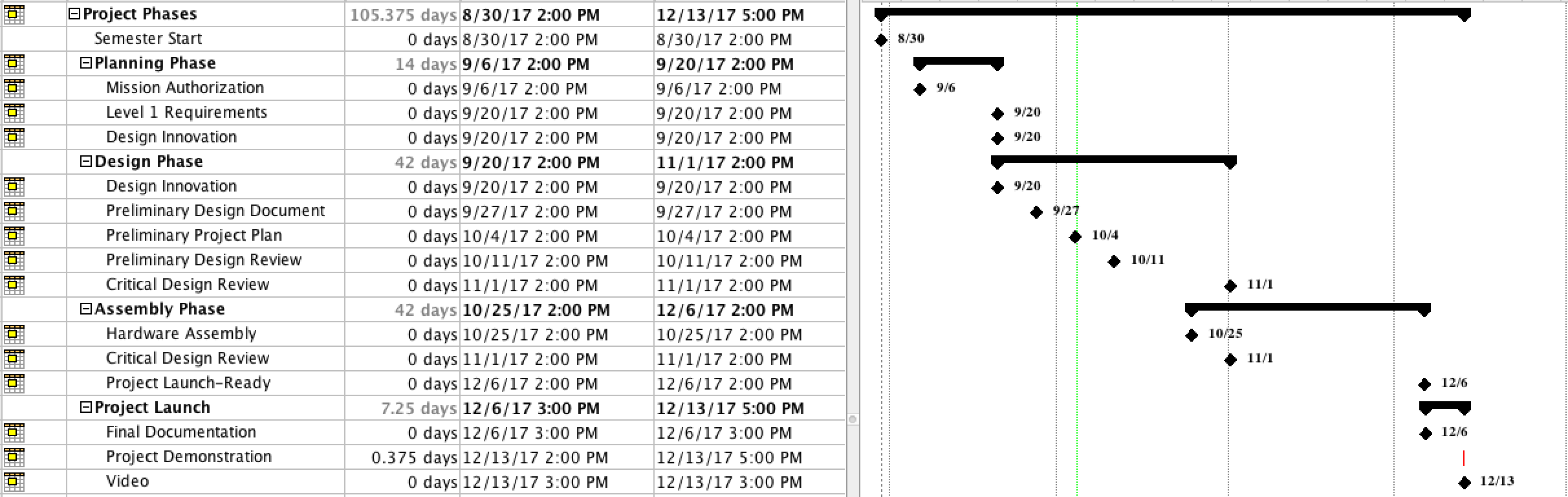
This layout provides the layout of due dates for the ModWheels project.
System/Subsytem Level Tasks
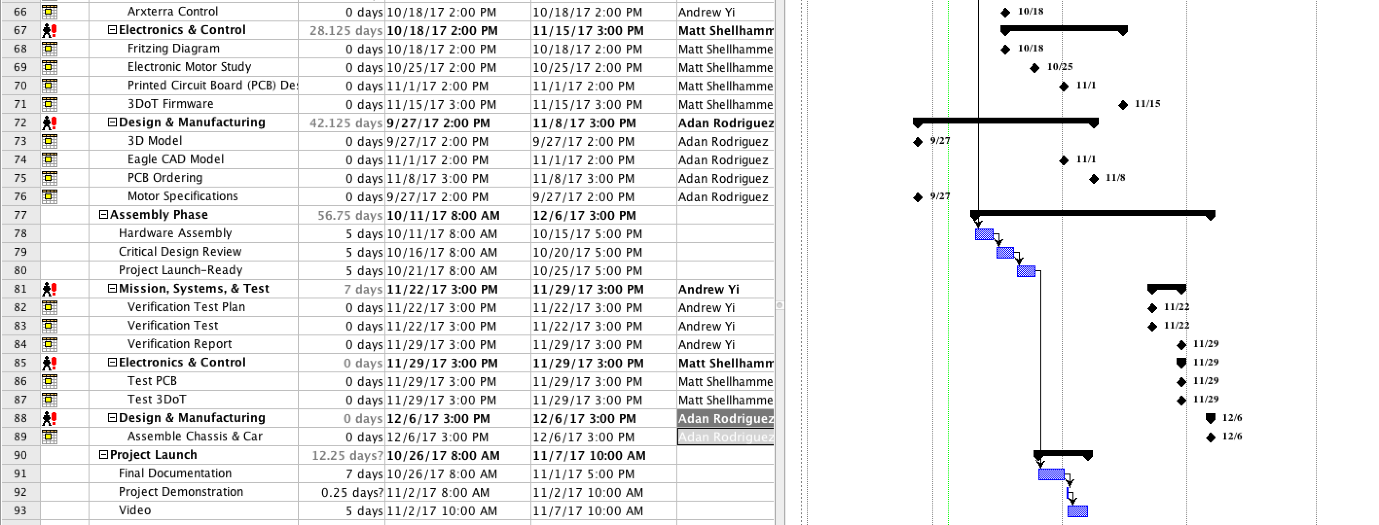
This layout provides the layout of due dates and assignments for engineers for the ModWheels project.
BurnDown Schedule
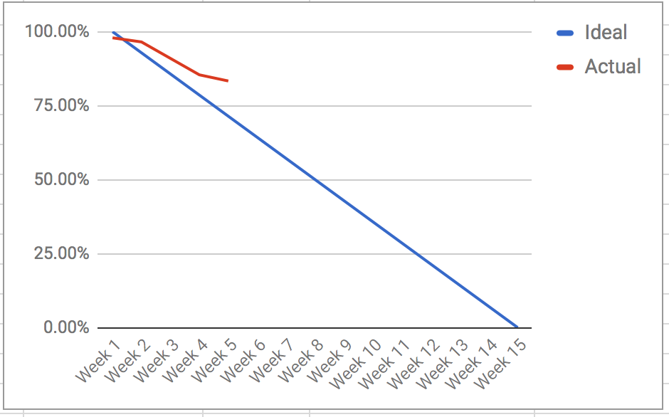
This layout provides the burn down for the ModWheels project.
Systems Resource Report
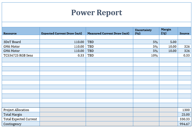
By: Andrew Yi (Mission, Systems, and Test Engineer)
Power Allocation Report

The power report is an overview of the power requirements of each physical component. The MST team is currently working with Professor Hill to finish the power chart for the 3DoT board. Once that task is finished, testing can begin on components to get test data.
Mass Allocation Report
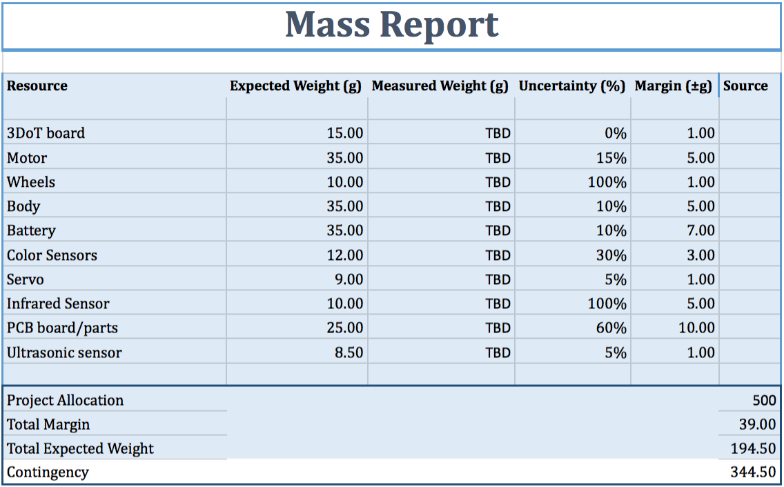
This report shows the mass of all the physical components used in the toy robot. There is quite a large amount of contingency because the rules of the maze has not been defined yet. Once those are defined, then the correct amount of sensors and components can be chosen.
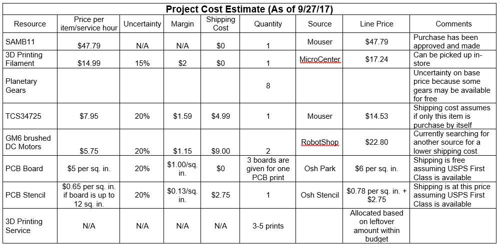
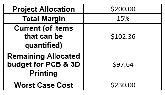
Project Cost Estimate
By: Lucas Gutierrez (Project Manager)
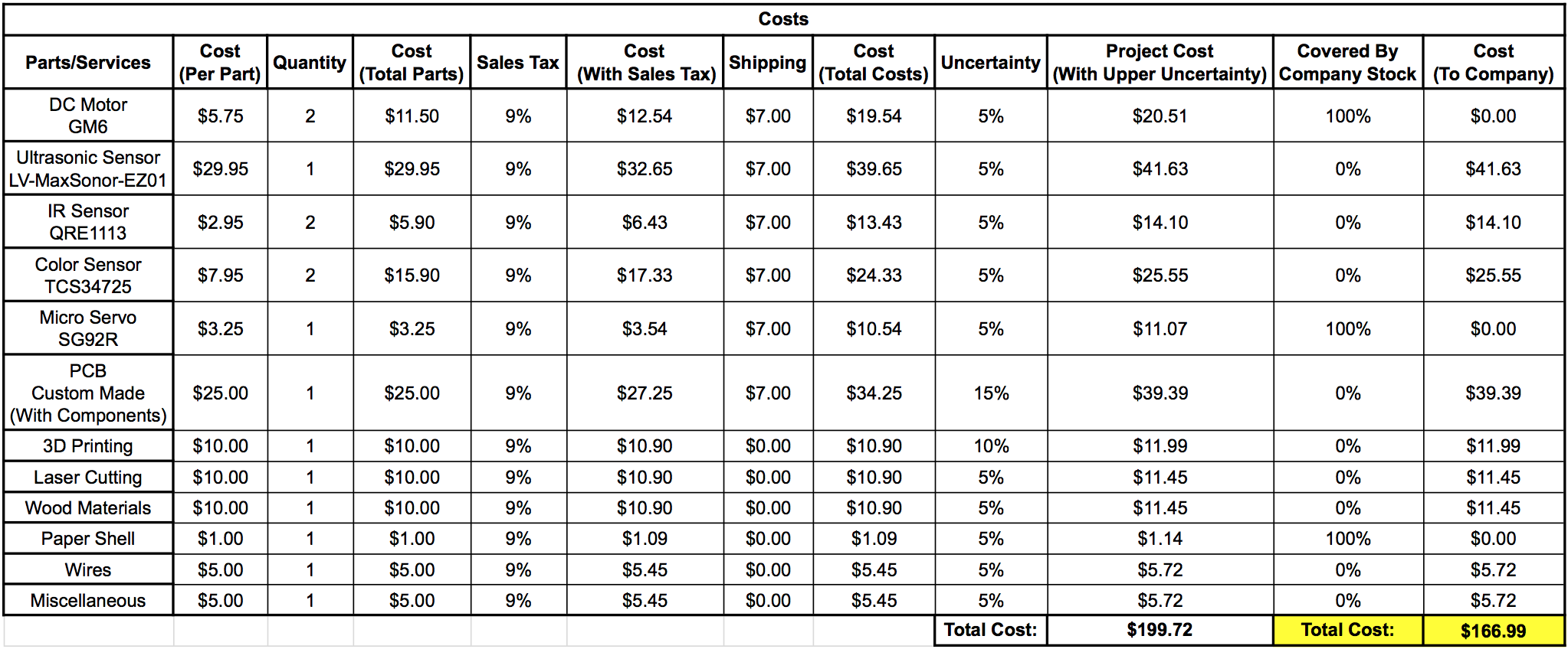
The cost report shows the current cost of components against the budget set by the customer. A larger pool of money was given towards the PCB board and components because of the uncertainty of certain sensors being required (maze rules). In case of laser cutting, money has been set aside to account for those costs.