Belinda Vivas (Project Manager)
Tyler Jones (Manufacturing)
Kevin Ruelas (Electronics)
By: Chastin Realubit (MST)
Executive Summary
Program Objective
By: Belinda Vivas (Project Manager)
The objective of the Second Generation of the Pick and Place is to:
❖Build up from the First Generation of the Pick and Place machine and create an user friendly design.
❖Create a user friendly manual:
- Softwares
- Step by Step
- Wiring
- Troubleshooting
❖It shall be built in stages.
❖Make the Pick and Place consistent with the manufacturer of only a few boards per semester.
Mission Profile
By: Belinda Vivas
The mission plan for the Second Generation Pick and Place is to place all components used for the 3Dot Board 4.54 faster than a person. Manufacturing time of a person is 4 hours, so anything less than that is acceptable, with 1 hour being the target time.
The overall goal of this project is to have a working Pick and Place machine for future EE400D students to build their custom PCB. The 3Dot Board that will be constructed is more difficult than any PCB students will make, therefore, this machine can theoretically make any board future students plan to do.
Because this machine is supposed to be used by students, we will include manuals (written and video) so that future generations can operate this machine with ease. We will conduct experiments using Electrical Engineering students to see if they can operate the machine using only the given manuals.
The overall summary for the Mission Profile is:
❖To create a 3-Dot 4_54 PC Board.
❖Ensure precision and calibration through the addition of a camera system (Edge Detection).
❖Create a CSV file to implement a better interface between the user and the machine.
❖Multiple feeder assemblies
❖Incorporate better materials
❖Tape feeder for the following component parts:
Design
Project Features
By: Belinda Vivas (Project Manager)

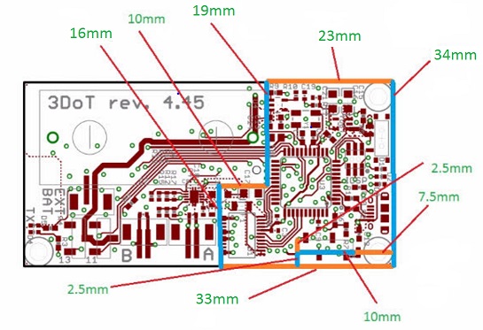
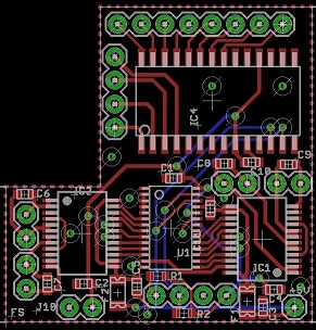
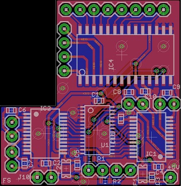
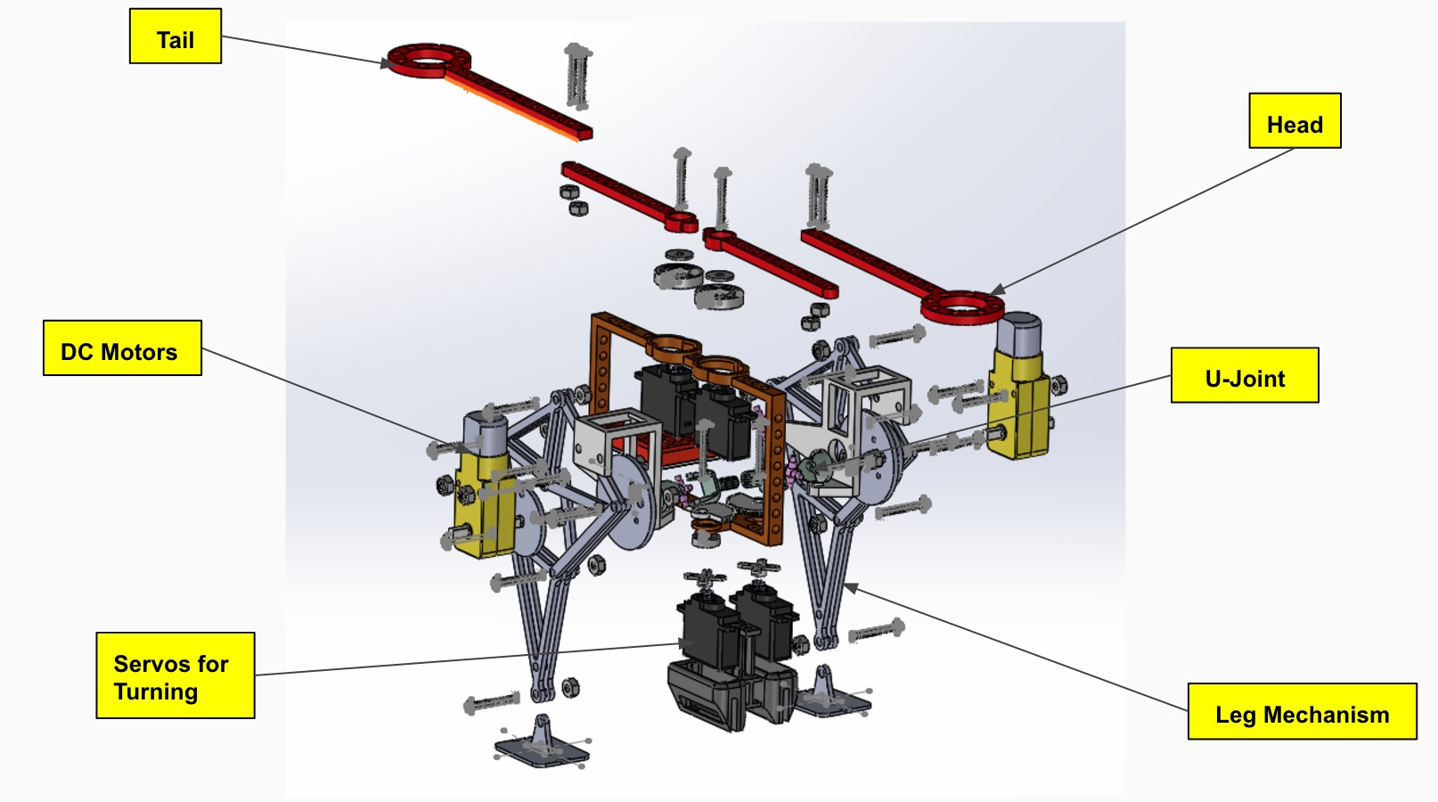
Figure 1 – Detailed Design of Generation 2
Electronics:
❖Camera System
❖Two Arduinos System
- Independent from each other
❖Vacuum System
❖Servos System
❖Power Emergency Switch
- Relay to cut power on the motors
Manufacturing:
❖Higher legs with rubber on the base to provide better stability due that more weight is being added causing for higher vibration.
❖Higher amount of component feeders.
❖IC Chip component holder
❖Power Switch
❖Camera
❖Component Cabinet
❖Electronics Cabinet
❖Tape waste bin
System Design
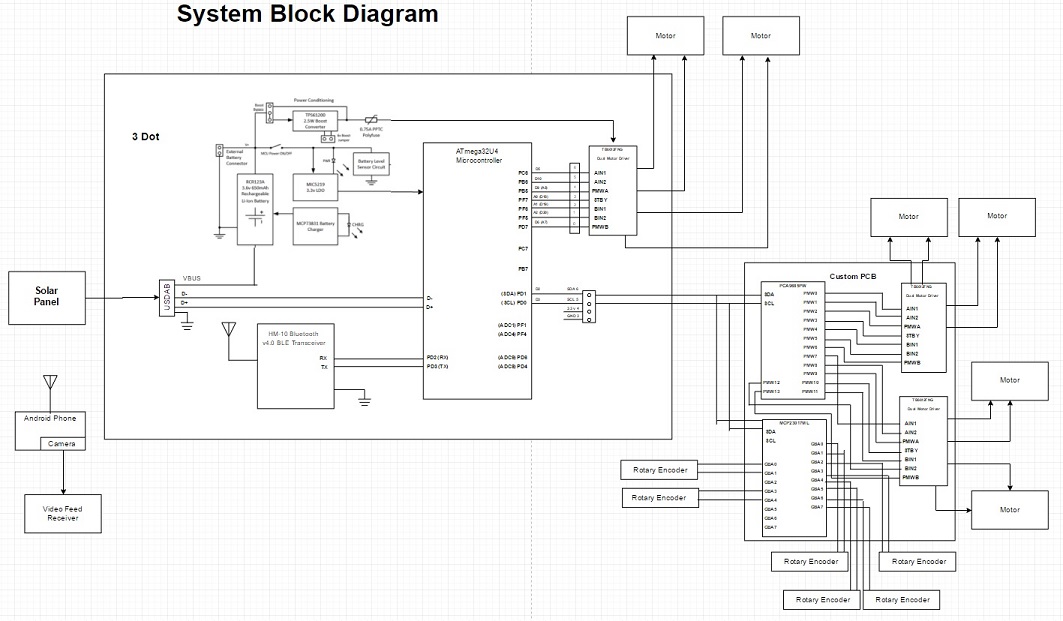
By: Chastin Realubit (MST)

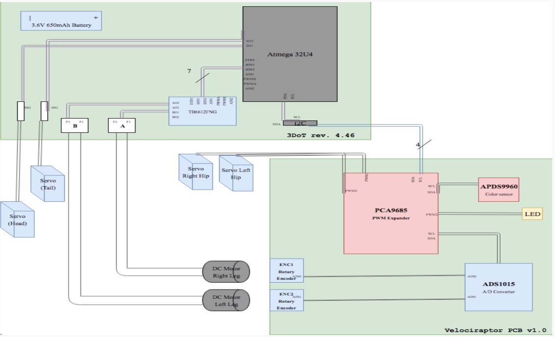
Figure 2 – System Block Diagram
Testing
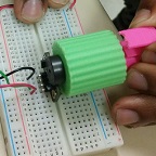
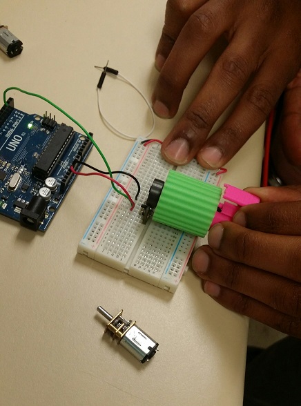
Solenoid and Vacuum Test
By: Tyler Jones (Manufacturing)
The vacuum by itself was powerful enough to carry the Atmega chip but experiments show that we need a bigger nozzle to increase airflow.

Figure 3 – Solenoid Circuit
Blog Post: https://www.arxterra.com/pick-and-place-solenoid-valve-design-and-control-2/
Z-Axis Test
By: Chastin Realubit (MST)
Z-Axis Motor: We did an experiment to see the load that the Z-Axis can handle and we found that it will still carry up to 2000 g. This experiment was done so that we can see if the motor can still move up and down even with more load. This was needed because we are adding a camera on the Z-Axis and we needed the system to still function with extra weight.

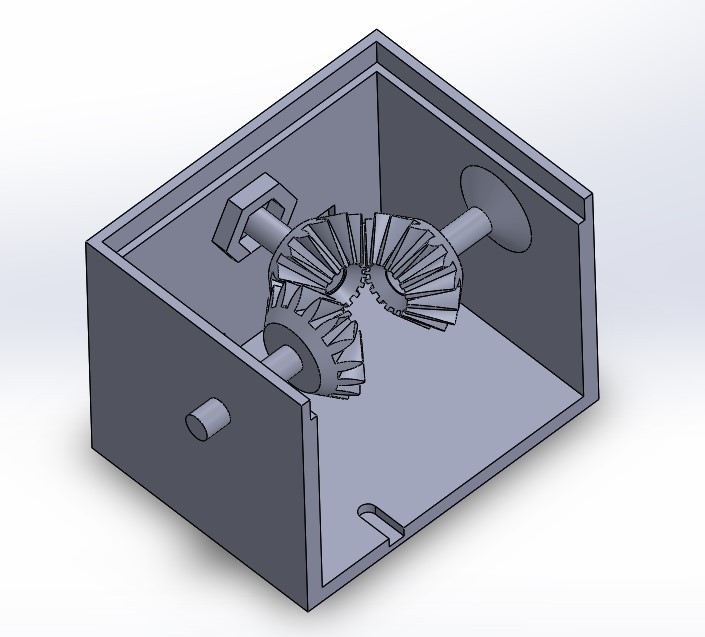
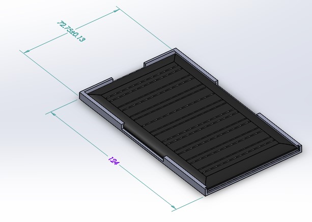
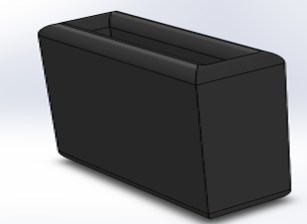
Figure 4 – Nozzle System
Blog Post: https://www.arxterra.com/pick-and-place-z-axis-and-nozzle-test/
Rubber Vibration Damping Test
By: Tyler Jones (Manufacturing)
-The machine has a basic feature of rubber shoes for legs of the platform stand.
-This will aid in damping vibrational disturbances.
-A 4” x 4” x 1” block of butyl rubber shaped using a bandsaw and miter saw.
-The block was fitted to form shoes that fit over the legs of the machine.
-The blocks have been tested on one leg for stability.
-The use of a milling router machine should be used

Additional Testing
Emergency Power Switch: https://www.arxterra.com/pick-and-place-emergency-power-switch/
By: Tyler Jones (Manufacturing)
3Dot IC Tray:https://www.arxterra.com/pick-and-place-3dot-ic-tray/
By: Tyler Jones (Manufacturing)
12 Servo Mount & Tape Feeder System:https://www.arxterra.com/pick-and-place-12-servo-mount-tape-feeder-system/
By: Tyler Jones (Manufacturing) and Belinda Vivas (Project Manager)
Camera Test: https://www.arxterra.com/pick-and-place-camera-test/
By: Kevin Ruelas (Electronics)
Solenoid Valve Design and Control:
By: Tyler Jones (Manufacturing) and Kevin Ruelas (Electronics)
Servo Driver: https://www.arxterra.com/pick-and-place-servo-driver/
By: Kevin Ruelas (Electronics)
Camera System: https://www.arxterra.com/pick-and-place-trade-off-study-camera-system/
By: Kevin Ruelas (Electronics)
User Interface
GRemote
By: Kevin Ruelas (Electronics)
Though the user can type commands manually in the GRemote, once the machine is running and calibrated, use command G28 to set the origin then send the CNC file and wait for the machine to do the rest.

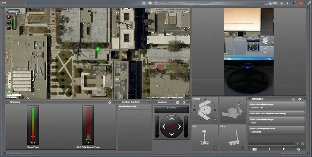
Figure 7 – GRemote controller

Figure 8 – GCode Commands
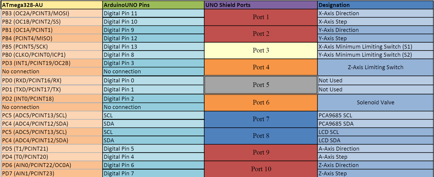
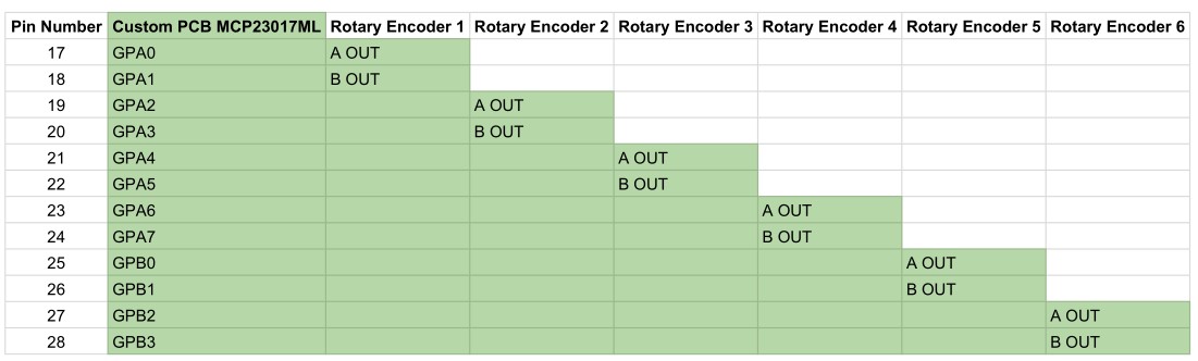
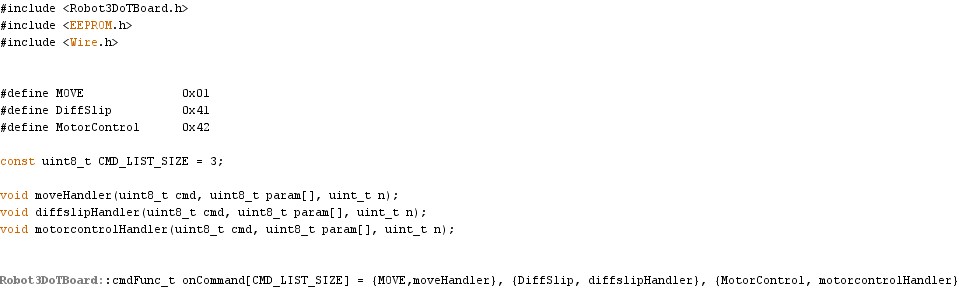
Figure 9 – Arduino 1 Interface Definitions
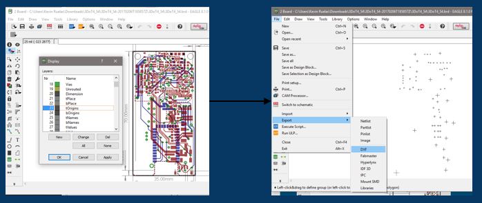
Figure 10 – Eagle CAD to Pick and Place
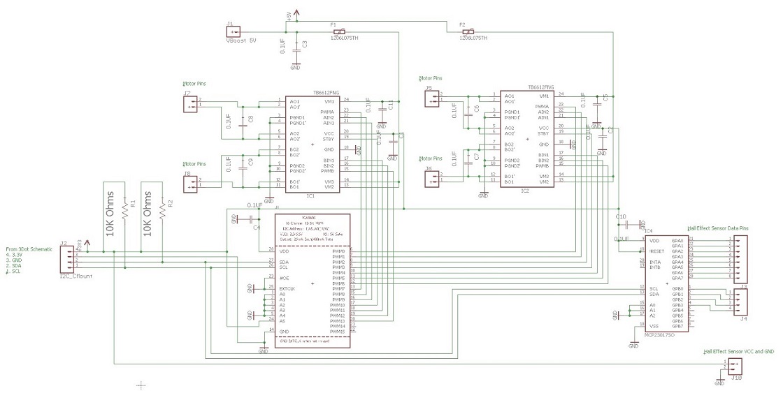
Camera Fritzing Diagram
By: Kevin Ruelas (Electronics)
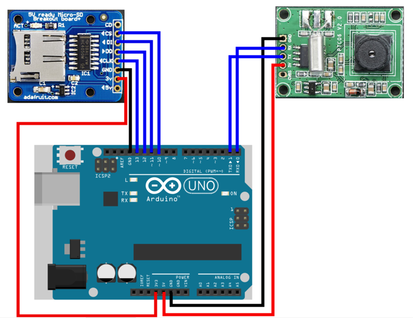
Figure 11 – Camera Fritzing Diagram
Recalibration of Origin
By: Kevin Ruelas (Electronics)
Since the 1st Gen. already defined the origin, the edge detection of a “target” will be used to calibrate this location and prompt the user to make this correction via GRemote.
Electronics Design
By: Kevin Ruelas (Electronics)
The overall Pick and Place was composed of various subsystems which were all ran by a common code. The motors, the nozzle, calibration, camera, LCD display, servo driver, and solenoid.

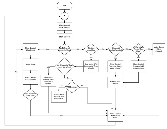
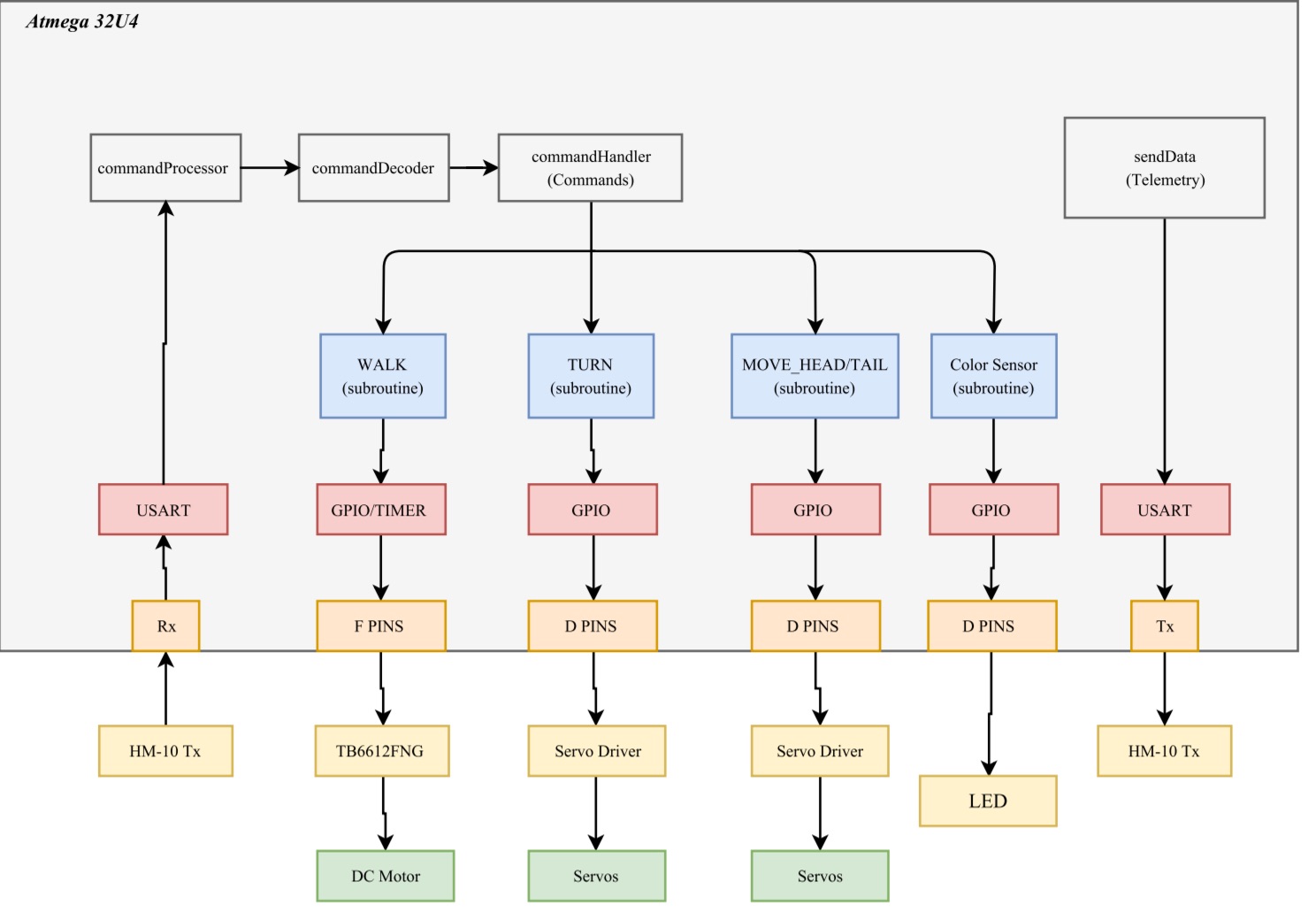
Figure 12 – High Level Software
Blog Post: https://drive.google.com/open?id=0B9iWYCBTJWEEeEFxc1pjU0ZFTjQ
SolidWorks Model
By: Tyler Jones (Manufacturing)
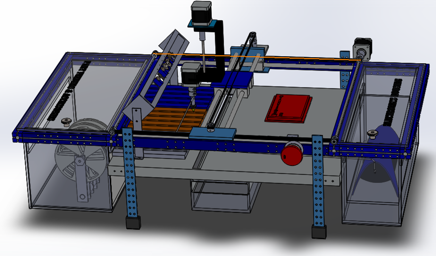
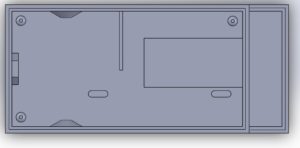
Figure 13 – Side View of SolidWork Design

Figure 14 – SolidWorks Top View Design
Verification and Validation Test
By: Chastin Realubit (MST)
The purpose of this section is to provide a comprehensive Verification and Validation (V&V) Test Plan of the Spring 2017 Pick and Place including the Project ConOps/Mission, Test Methodology, Verification and Validation Matricies, Test Cases, and Exit Criteria.
https://drive.google.com/open?id=0B9iWYCBTJWEEU05NMy1SMUs2ajQ
Resource Allocations
Power Allocation
By: Chastin Realubit (MST)
| Components |
Expected Current Draw (A) |
Uncertainty (%) |
Margin (±A) |
Measured Current Draw(A) |
| Stepper Motor (X-Axis) |
1.35 |
5% |
.0675 |
.44 |
| Stepper Motor (Y-Axis) |
1.35 |
5% |
.0675 |
.44 |
| Stepper Motor (Z-Axis) |
1.35 |
5% |
.0675 |
2.83 |
| Stepper Motor (A-Axis) |
1.35 |
5% |
.0675 |
.44 |
| Detection Camera |
.75 |
5% |
.0375 |
TBA |
| Solenoid Valve |
.40 |
5% |
.02 |
.42 |
| Display Screen |
.75 |
5% |
.0375 |
TBA |
| Servo fs90r (12) |
.2 |
5% |
.01 |
.21 |
| Project Allocation |
6 A (Calculated knowing that we will be using two Arduinos with separate power supplies) |
| Total Expected Current |
3.45 A (The motors and servos will not run simultaneously) |
| Total Margin |
.375 A |
| Contingency |
2.175 A |
Mass Allocation
By: Chastin Realubit (MST)
|
| Vacuum System Components |
Preliminary Mass (g) |
Uncertainty (%) |
Margin (±g) |
Expected Mass (g) |
Actual Mass (g) |
| Stepper Motor (A-Axis) |
245.00 |
5% |
12.25 |
245.00 |
247 |
| Stepper Motor (Z-Axis) |
245.00 |
5% |
12.25 |
245.00 |
246 |
| Vacuum Nozzle |
2 |
5% |
.1 |
2 |
TBA |
| Z-Axis Actuator |
292.00 |
5% |
14.6 |
300 |
244.12 |
| Detection Camera |
3 |
5% |
.15 |
3 |
TBA |
| Project Allocation |
.Preliminary allocation is 2000g |
| Total Expected Mass |
795 g |
| Total Margin |
39.35 g |
| Total Actual Mass |
TBA |
| Contingency |
1165.65 g |
|
|
|
|
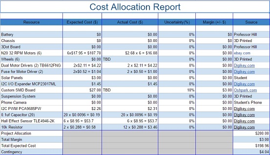
Cost Report
By: Belinda Vivas (Project Manager)
For the Second Generation of the Pick and Place, our allotted project budget was of $500, in which a total of $469.04 was spent; it was divided as follow:
| Receipt |
Vendor |
Item |
Unit |
Quantity |
Total Cost (Including Shipping) |
Purchased By |
| 1 |
Makeblock |
RJ25 Adapter |
$4.98 |
1 |
$15.65 |
Kevin Ruelas |
| RJ25 cable-20cm (4-pack) |
1 |
| 2 |
Amazon |
12 Bit PWM Servo Driver |
$11.99 |
1 |
$11.99 |
Kevin Ruelas |
| 3 |
Amazon |
Blue Backlight LCD Module |
$7.99 |
1 |
$7.99 |
Kevin Ruelas |
| 4 |
Amazon |
3-Pin Extension Lead Wire |
$6.99 |
1 |
$6.99 |
Kevin Ruelas |
| 5 |
Amazon |
Arduino Power Supply Adapter |
$6.29 |
1 |
$6.29 |
Kevin Ruelas |
| 6 |
Amazon |
120 pcs Dupont Wire |
$8.86 |
1 |
$8.86 |
Kevin Ruelas |
| 7 |
This item was removed. Arduino Uno will not be needed for the project anymore and the student requested to keep the board. |
| 8 |
AdaFruit |
MicroSD Card |
$7.50 |
1 |
$52.56 |
Kevin Ruelas |
| JPEG Camera |
$35.95 |
1 |
| 9 |
Pololu |
Rotation Servo |
$4.95 |
9 |
$49.50 |
Chastin Realubit |
| 10 |
GearBest |
LCD Display Screen |
$4.53 |
1 |
$17.18 |
Chastin Realubit |
| 11 |
Amazon |
PWM Servo Driver |
$11.99 |
1 |
$15.98 |
Chastin Realubit |
| 12 |
Ebay |
Rubber Bench Block |
$7.48 |
1 |
$7.48 |
Tyler Jones |
| 13 |
Sewvac LTD |
Bobbins for Servos |
$3.29 |
1 |
$3.29 |
Tyler Jones |
| 14 |
RadioShack |
Mosfet IRF 510 |
$1.78 |
1 |
$1.78 |
Tyler Jones |
| 15 |
ACE Hardware |
Nuts & Bolts |
$5.40 |
1 |
$5.93 |
Tyler Jones |
| 16 |
The Home Depot |
Wood |
$29.98 |
1 |
$29.98 |
Tyler Jones |
| 17 |
The Home Depot |
Aluminum Plates & Epoxy |
$35.68 |
1 |
$38.45 |
Tyler Jones |
| 18 |
MicroCenter |
3D Printer Filament |
$14.99 |
1 |
$16.15 |
Tyler Jones |
| 19 |
The Home Depot |
Screws |
$18.49 |
1 |
$18.49 |
Tyler Jones |
| 20 |
The Home Depot |
Plastic Sheet |
$140.06 |
1 |
$140.06 |
Tyler Jones |
| 21 |
ACE Hardware |
Screws |
$14.44 |
1 |
$14.44 |
Tyler Jones |
|
|
|
|
|
|
|
|
|
|
|
Total: |
$469.04 |
|
| Name of Individual |
Position |
Total Amount Reimbursed |
| Kevin Ruelas |
Electronics |
$110.33 |
| Chastin Realubit |
MST |
$82.66 |
| Tyler Jones |
Manufacturing |
$276.05 |
|
|
|
|
Total** |
$469.04 |
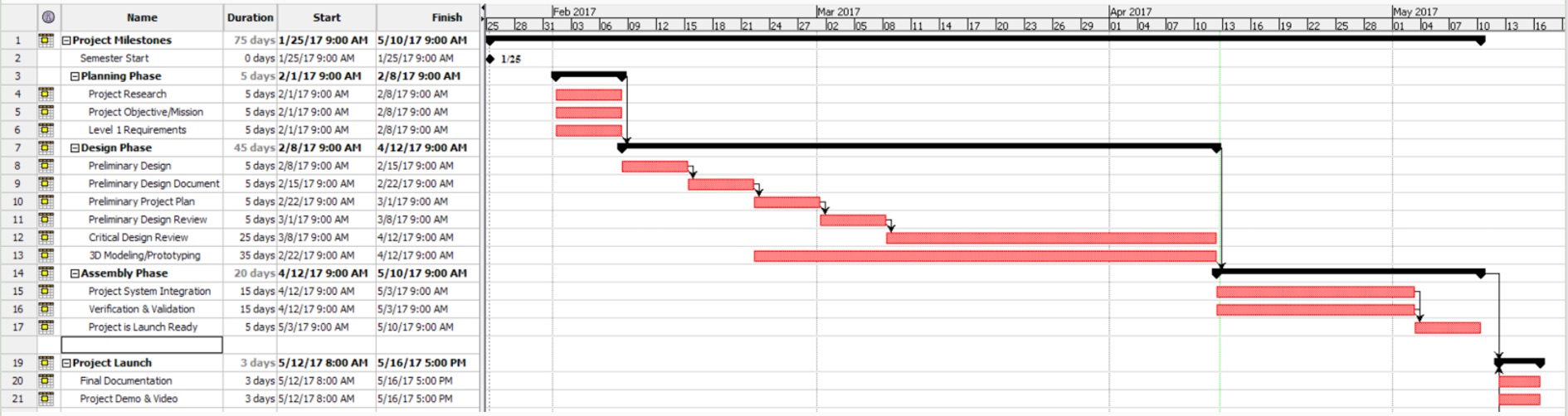
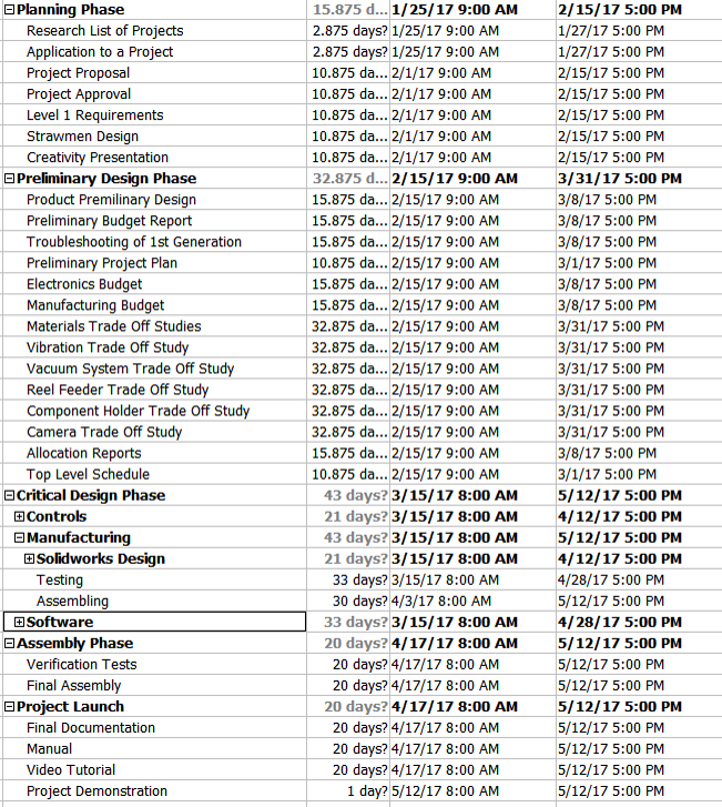
Updated Schedule
Top Level Schedule
By: Belinda Vivas (Project Manager)
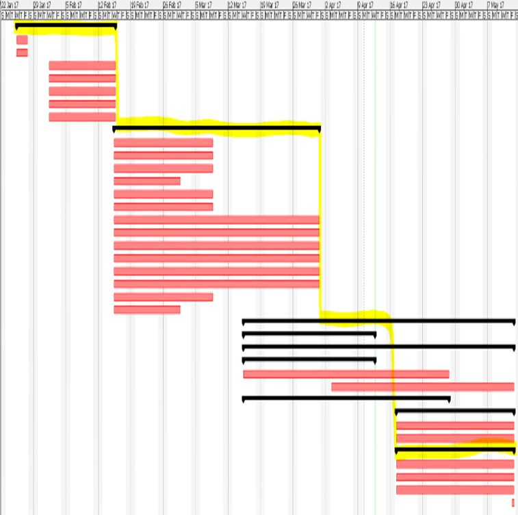
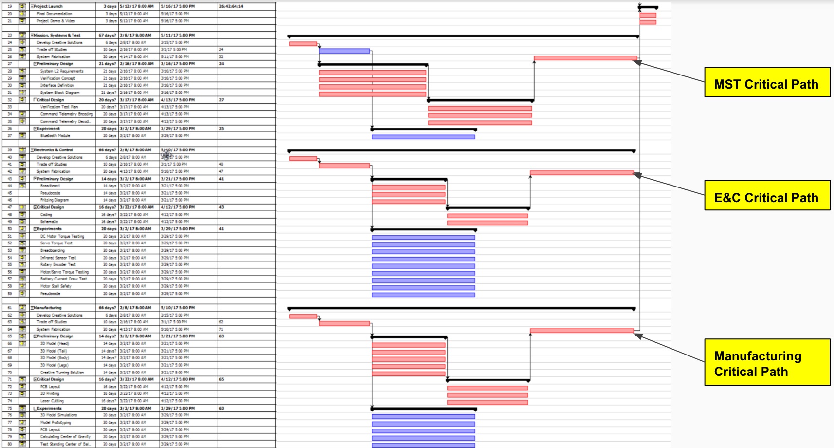
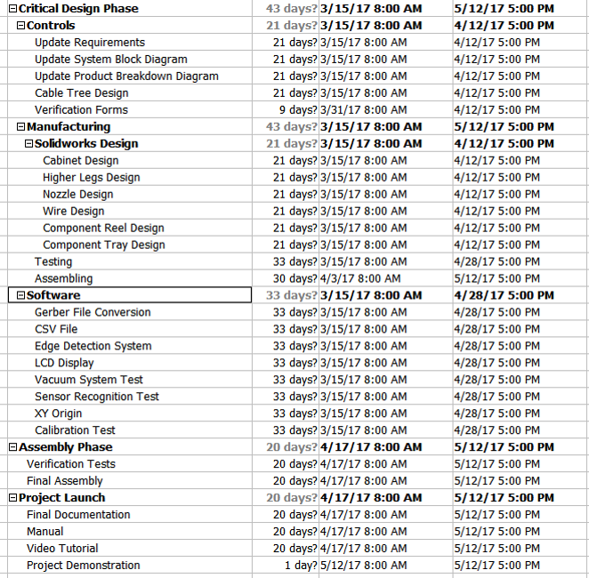
Sub System Schedule
By: Belinda Vivas (Project Manager)

Concluding Thoughts
By: Belinda Vivas (Project Manager) and Tyler Jones (Manufacturing)
We were able to incorporate more extensive and higher technology subsystems into the Second Generation of the Pick and Place; by implementing a more user friendlier systems and introducing a camera system, LCD Display system, redesign of the nozzle, better calibration system, higher servo driver system, and an overall new manufacturing design.
The pick and place was successful in picking and placing parts onto the 3DoT board. The machine when calibrated can place parts into the respective locations where they can be soldered using the IR reflow machine. It is important however to note that the pick and place machine can be improved in the following areas. Its mechanical, and electronic design can be updated with simple solutions that require more time. They are discussed below.
The pick and place mechanical design can be improved in a noticeable and easily recognizable ways with more time for development. The first is the belt system.
1) The belt system does work well, and the X and Y stepper motors move to positions accurately, sometimes during design of the machine the tensioner plates that hold the 3 belts into place were loosened. This is so that parts in the machine can be easily worked on. Therefore it is important to make sure that belts are tight, as well as lubricated. Loose belts cause the machine to make a noticeable sound that is not as fluid as when they are tight. The best solution would be to incorporate threaded drives instead of belts, however this is more costly.
2) The pick and place uses a 3DoT board that was 3D printed with more than 6 iterations. This was due to numerous errors in the printing temperature, malfunction, and design limitations. There is a table that corresponds to part sizes and dimensions and adjustments made to account for error of the 3D print. It is found here, 3DoT IC Tray. A decent 3D printer and filament must be used in order to get the precise dimensions necessary. An alternative solution would be to cut a small rectangular piece of plastic that is about 0.5-0.75 inches thick, and have it precisely laser cut. The laser cutter used in the design center was not accessible in this generation later on in the project timeline.
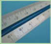
3) The Z-axis is supported by two aluminium slider rods. These slider rods must be spaced as far apart as possible so that the heavier Z-Axis can have a wider more stable base and center of gravity. This design was used in the pick and place and must be incorporated if further design iterations will be made. The camera is mounted on a bracket that allows makes it so that the Z-Axis only can be bolted to two of the aluminium sliders. This must be made able to be bolted into all four of the sliders. It is shown below

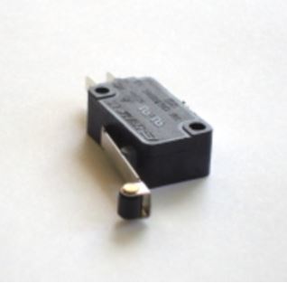
4) The pick and place currently uses a locked position origin. This is so that the the machine can be turned off and moved back to the locked position manually. From here the pick and place machine can be moved to the function “L” bracket origin. It would be a much safer design if limit switch can be placed on the X and Y axis so that if the user were to accidentally enter the wrong code in the machine the motors would not grind. This can be accomplished by using the current limit switches and adding the limit switch code to the stepper motor.ino Arduino code. The limit switch acts as an electromechanical disconnect that simply switches off the stepper motors when the machine makes contact with the switches. An image of the switch is shown below.
5) The electronic design can be further enhanced if the 12 channel servo driver can be made to separate the digital power source which carries Arduino logic level signals of +3.7V and +5.0V, and the analog power source which carries +12V signals. The connection is made through the Me Uno RJ25 board. This connects an an RJ 25 communications signal with a 12 V analog signal.
6) The edge detection camera code was functional and the code calculated the position of the origin by comparing picture taken by the camera, and comparing the pixel lengths. The edge detection however was off by about 0.3 which is about 1mm in actual length. In order to improve the accuracy of the machine a higher resolution camera must be used.
Project Resources
Video – https://www.youtube.com/watch?v=2Cn5abf5Arw
Preliminary Design Document – https://www.arxterra.com/pick-and-place-preliminary-design-document/
Preliminary Project Plan – https://www.arxterra.com/pick-and-place-preliminary-project-plan/
PDR: https://drive.google.com/open?id=0B9iWYCBTJWEES1g1emo3NklpTmc
CDR: https://drive.google.com/open?id=1tGSSGGry0n6I4EDJ9IYzM1PXZUMOc_jJTCyYj9YSV1E
Blog Posts: https://drive.google.com/open?id=0B0hJ_mPvve6CRVpqOU1mdUN2aFk
Code Files: https://drive.google.com/open?id=0B0hJ_mPvve6CY0t5SjNuWk1OOEk
3Dot BOM: https://drive.google.com/open?id=1rC5BPWV3KqwXsGQ3CgFeVNoKTumOvdZjCftwd7t0eEU
Servos BOM: https://drive.google.com/open?id=0B7gruONfGRYcUExJeVBxMzNYblU
GCode Commands: https://drive.google.com/open?id=1CKODeCrm8FpmgrmSp363mjAMPNYaCCe5904dLSit4cs
3Dot 3D print File: https://drive.google.com/open?id=0B0hJ_mPvve6CNXVTQVNyVGxCT3c
3Dot Board: https://drive.google.com/open?id=0B0hJ_mPvve6CN25OSU01aEcwWlE
https://drive.google.com/open?id=0B0hJ_mPvve6CN2dIZHZXTzAtSWs
Ace Converter: https://drive.google.com/open?id=0B0hJ_mPvve6CTlI1NzNHX1BTLTQ
Arduino: https://drive.google.com/open?id=0B0hJ_mPvve6Ca1BpM3FGNDYzWVE
GCode: https://drive.google.com/open?id=0B0hJ_mPvve6CM2pNZ2hCWl9ZMXc
Me Uno Shield: https://drive.google.com/open?id=0B0hJ_mPvve6CUmtDcEN5LUxQSjg
Meeting Minutes: https://drive.google.com/open?id=0B0hJ_mPvve6CNXRhRFd5RThkR1k
Research: https://drive.google.com/open?id=0B0hJ_mPvve6CeS1tQmFRQ3hqQ3c
SolidWorks Files: https://drive.google.com/open?id=0B0hJ_mPvve6CaFVoR1RaRl93bkE
XY-Plotter: https://drive.google.com/open?id=0B0hJ_mPvve6CckVuWkJvOU53eEE
All Files: https://drive.google.com/open?id=0B0hJ_mPvve6CNXVTQVNyVGxCT3c
Instructional Manual: https://drive.google.com/open?id=1eXx-_8FduTJi8nRR356R3nj0DHnTqq50er3VYreTGXA
Project Libre Schedule: https://drive.google.com/open?id=0B9iWYCBTJWEET2pLMHVJVVd2am8
Verification and Validation: https://drive.google.com/open?id=0B9iWYCBTJWEEU05NMy1SMUs2ajQ