
S17 Prosthetic Arm: Kill Switch Test
This test if performed to try to confirm that a switch on the V- path back to battery is able to turn off the prosthetic arm and hand system without damaging other electronic components.
This test if performed to try to confirm that a switch on the V- path back to battery is able to turn off the prosthetic arm and hand system without damaging other electronic components.
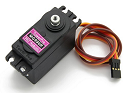
This test is done to make sure the servo in the prosthetic arm can handle the weight of the prosthetic hand and any object that it’s holding while still being about to rotate vertically, with the orientation in the direction of the ground.
The Mode Selector Test is done to check if we can enter different modes using the Flex Sensors that were tested in an earlier blog post to control the movements of the Prosthetic Hand by syncing different types of movements of the hand to different modes that are achieved by syncing the modes to different movements of the flex sensors.

This test is done in order to choose the proper battery to use for the prosthetic arm and hand, and then to figure out how much capacity the battery has, and what the voltage rating of the battery is.
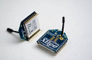
We completed this test to verify the hook up of the Xbee so we can design a shield for it, as well as getting the Xbee to be able to send and receive data from a wireless source. Ex hand to foot and vice versa.

By Renpeng Zhang
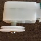
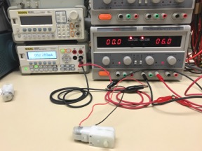
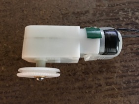
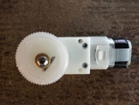
Demoing control of a stepper motor.
Table of Contents
In this demo, I tested the 28BYJ-48 stepper motor with the ULN2003 stepper motor driver. I used one Arduino for the control of the stepper motor. Since it’s recommended to use an external power source, I just used another Arduino solely for the purpose of providing 5V DC to the motor driver. I was able to control the stepper motor to do rotate clockwise and counter clockwise.

Arduino code:
/*
* 28BYJ48 stepper motor code
* Connect:
* IN1>>D8
* IN2>>D9
* IN3>>D10
* IN4>>D11
* Vcc 5V source, prefered external 5V source
* Gnd
*/
#define IN1 8
#define IN2 9
#define IN3 10
#define IN4 11
int Steps=0;
boolean Direction=true;// gre
unsigned long last_time;
unsigned long currentMillis;
int steps_left=4095;
long time;
void setup() {
Serial.begin(115200);
pinMode(IN1, OUTPUT);
pinMode(IN2, OUTPUT);
pinMode(IN3, OUTPUT);
pinMode(IN4, OUTPUT);
// delay(1000);
}
void loop() {
while(steps_left>0){
currentMillis = micros();
if(currentMillis-last_time>=1000){
stepper(1);
time=time+micros()-last_time;
last_time=micros();
steps_left–;
}
}
Serial.println(time);
Serial.println(“Wait…!”);
delay(2000);
Direction=!Direction;
steps_left=4095;
}
void stepper(int xw){
for (int x=0;x<xw;x++){
switch(Steps){
case 0:
digitalWrite(IN1, LOW);
digitalWrite(IN2, LOW);
digitalWrite(IN3, LOW);
digitalWrite(IN4, HIGH);
break;
case 1:
digitalWrite(IN1, LOW);
digitalWrite(IN2, LOW);
digitalWrite(IN3, HIGH);
digitalWrite(IN4, HIGH);
break;
case 2:
digitalWrite(IN1, LOW);
digitalWrite(IN2, LOW);
digitalWrite(IN3, HIGH);
digitalWrite(IN4, LOW);
break;
case 3:
digitalWrite(IN1, LOW);
digitalWrite(IN2, HIGH);
digitalWrite(IN3, HIGH);
digitalWrite(IN4, LOW);
break;
case 4:
digitalWrite(IN1, LOW);
digitalWrite(IN2, HIGH);
digitalWrite(IN3, LOW);
digitalWrite(IN4, LOW);
break;
case 5:
digitalWrite(IN1, HIGH);
digitalWrite(IN2, HIGH);
digitalWrite(IN3, LOW);
digitalWrite(IN4, LOW);
break;
case 6:
digitalWrite(IN1, HIGH);
digitalWrite(IN2, LOW);
digitalWrite(IN3, LOW);
digitalWrite(IN4, LOW);
break;
case 7:
digitalWrite(IN1, HIGH);
digitalWrite(IN2, LOW);
digitalWrite(IN3, LOW);
digitalWrite(IN4, HIGH);
break;
default:
digitalWrite(IN1, LOW);
digitalWrite(IN2, LOW);
digitalWrite(IN3, LOW);
digitalWrite(IN4, LOW);
break;
}
SetDirection();
}
}
void SetDirection(){
if(Direction==1){Steps++;}
if(Direction==0){Steps–;}
if(Steps>7){Steps=0;}
if(Steps<0){Steps=7;}
}

By Edgardo Villalobos
Calculations to find what voltage and current the solar cells need to provide to charge the battery in 8 hours.
Table of Contents
Rule of thumb: Solar Panel Voltage = Battery Voltage x 1.5
Solar Panel Voltage = 12-V x 1.5
Solar Panel Voltage = 18-V
Rule of thumb: Amps = Amp Hours / Hours
Amps = 7-Ah / 8-hrs Amps = 10-Ah / 8-hrs
Amps = 875-mA Amps = 1.25-A
By: Shaun Pasoz
Electronics & Control Engineer
Torque testing allows the designer to see if a desired motor can output enough force to physically move a robot. To perform the test, a rig was designed in which the motor was clamped down with a fixed radius on the output shaft. Varying weights were then hung from the fixture using a very thin fishing line. This setup allowed for the force pulling the weight down from gravity to always be tangential to the fixed radius, allowing for simpler calculations of torque using the following formula:
τ=rFsin(θ)
The variables used to find torque are:
Since the designed rig allows the force to always be tangential to the radius, the equation is simplified to τ=rF. To control the amount of force on the radius, the weights are used to continually increase the force. Therefore, the final equation for calculating the torque is:
τ=r*mg
The following tables show the data measured during the torque testing:
| Motor: | Sparkfun MicroGear Motor @5V | ||
| Mass (g) | Current Draw (mA) | Radius of Fixture (mm) | Torque (Oz-In) |
| 0 | 32.7 | 1.50 | 0 |
| 250 | 38.5 | 1.50 | 0.520 |
| 300 | 40.8 | 1.50 | 0.625 |
| 500 | 44.5 | 1.50 | 1.04 |
| 700 | 48.6 | 1.50 | 1.46 |
| 1000 | 55.1 | 1.50 | 2.08 |
Table 1: Sparkfun Torque Testing Data
| Motor: | Pololu MicroGear Motor @3.3V | ||
| Mass (g) | Current Draw (mA) | Radius of Fixture (mm) | Torque (Oz-In) |
| 0 | 40.1 | 1.50 | 0 |
| 500 | 114.8 | 1.50 | 1.04 |
| 700 | 128.5 | 1.50 | 1.46 |
| 900 | 141 | 1.50 | 1.87 |
Table 2: Pololu Torque Testing Data
Figure 2: Torque vs Mass Graph
Since both the radius, and the angle between the force applied and radius, the relationship between torque and mass is going to be the same for both motors. Where they begin to differ is when the other parameters of the motor are observed. For example, the current draw of the Pololu motor was over double with a 700 gram load on it. This is because the motor has been chosen to run at 3.3V instead of 5V to accommodate the customer’s needs.
The SpiderBot’s expected mass is 700g. The required torque to move 700g was calculated to be 1.46 ounce-inch. Both motors have a stall torque well above that, and therefore should be able to safely move the SpiderBot.
With the expected load, the Pololu motor RPM was calculated at 44 RPM. This was found by putting a piece of tape on the radius and counting the revolutions for 30 seconds three times and taking the average. Repeating the process for the Sparkfun motor; it’s RPM was calculated as 33.3 RPM. Some possible deviations may occur as possible sources of error include: neglecting the weight of the weight of the fishing line that pulled the weights, and not including the various friction points in the calculations. Overall, the motors should be able to move SpiderBot without damaging the 3DoT or our PCB.
By: Abraham Falcon (Electronics and Control)
Approved By: Alexander Clavel (Project Manager)
Table of Contents
Electronics and Control engineer job is to do an experiment on the D.C. motor to see if it can the handle the weight needed for the biped to walk. The following experiment was to determine if the chosen D.C. motor can handle the Biped’s total weight while one foot is off the ground and the other supports the entire system. The maximum stress weight of the Biped was chosen to be at 500 grams which is also what was used to determine out projects mass allocation. The test was also done to calculate exactly how much power consumption came from the D.C. motor and to determine if this would be acceptable to last up to the 30 minutes duration for the Pacman Game.
Table of results:
| Servo Motor | Stress Weight | Operating Voltage (Volts) | Stress Current
(Amps) |
| Pololu 200:1 Plastic Gearmotor | 500 grams | 6 volts | 100 mA |
This experiment was done by hooking up the D.C. motor to a battery rated at 6 volts and with a digital multimeter in series. The weight of 500 grams was attached to a custom-built pulley wheel that was attached to the shaft of the D.C. motor. Also the radius of the custom-built pulley wheel was measured out to be about 1cm.
Here is an example of the D.C. motor connection without the weight and you can see that with no load the D.C. motor runs at the highest of 62.289 mA
The setup from above picture was used but added a custom-built pulley wheel to the motor with a weight of 500 grams. The D.C. motor lifted the weight of 500 grams and the current was measured. From observation, this D.C. motor can handle the stress weight of the biped at 500 grames and the current was measured to be at its highest of 100 mA. All recorded results from this experiment is listed on the table of results above.
Here below are two pictures of the custom-built pulley wheel which was used for the experiment of Biped’s stress weight.
Performing this experiment, it showed that this Pololu 200:1 Plastic Gearmotor will allow for the Biped to be able to walk and also shows that for the current, the power consumption is low enough for the D.C. motor to be able to last for 30 minutes. This experiment concluded that this D.C. motor will work and it does fit our requirements for this Biped. In the references section, there is a video starting from 5:01 till 6:02 that shows how the custom-built pulley wheel was made and used for this experiment. The second reference was also a basing of the setup of this experiment to lift the weight and measure the current of the D.C. motor.
By: Mohammar Mairena, Electronics & Control Engineer
Approved by: Jesus Enriquez, Project Manager
Table of Contents
The torque needed to move the different parts of the robot are specified by the Design and Manufacturing engineer. By testing the torque required at a specific location of the robot, one can prove the servo chosen will handle the stress placed at a certain location.
Based on the measurements given by the Design and Manufacturing engineer, the servo placed at each hip will need to support 400 g at a horizontal position.
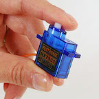
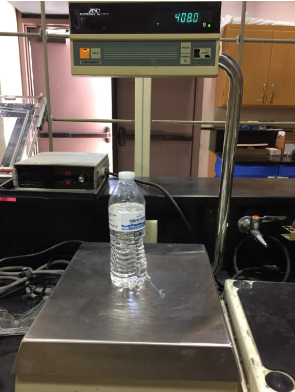
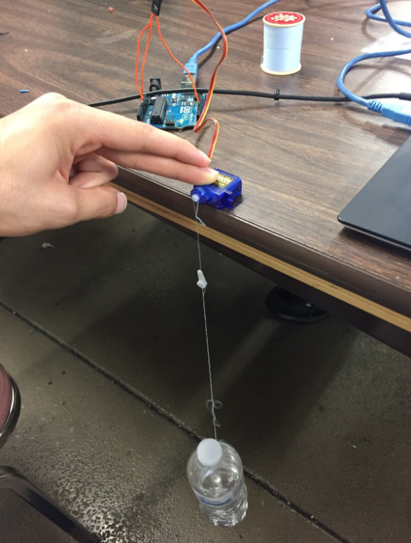
The experiment was done using a water bottle, HXT900 Micro Servo provided by Professor Hill, and a piece of string attached to the water bottle. The water bottle weighed approximately 408 grams, mimicking the weight that the servo (at the hip) will handle. The servo must rotate completely, without a stall under the 408 g load. The torque requirement at the hip was successful and rotated without a stall. Power came from the 3.3 V pin on the Arduino Uno and the current reading at 3.3 V came from the digital multimeter from the lab. At 3.3 V and under a 408 gram load, the HXT900 Micro Servo drew 180 mA of current.
Since the shaft radius of the servo is 2 mm and the weight of the water bottle is 408 grams, we can multiply them to get the Torque required at the hip. 2 mm converts to .2 cm, 408 g converts to .408 kg. Together, the torque required is .0816 kg*cm, which is equal to 1.13 oz-in.
| HXT900 Servo | Placement | Voltage | Current Drawn | Weight | Torque Needed | Shaft Radius |
| Hip | 3.3 V | 180 mA | 408 g | 1.13 oz-in | 2 mm |
It is important to note that at each hip, the servo will need to provide 1.13 oz-in of torque. As a result, the current drawn at each hip will be around 180 mA. Since the servos at the hips will only be used to make turns, the current drawn does not place much stress on the 3Dot battery. Max current output is 500 mA for the 3Dot Battery. The servos will not exceed the 500 mA limit.