Fall 2016 Velociraptor (W): Interface Matrix Update

By Gifty Sackey (Mission, Systems, Systems Engineer)

Approved by:

– Lam Nguyen (Project Manager)

– James Lee (Division Manager for Mission, Systems, and Test

Table of Contents


Introduction


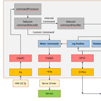
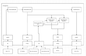
In this current block post, the interface matrix along with the eagle card documents have been provided and discussed in order to allow future 400D students to have a smooth transition when building upon the robot. The interface matrix excel document was designed based off the EAGLE CAD design which was designed by my groups electronics engineer. The EAGLE CAD allows us to have an idea of what our PCB will look like before actually printing it. With the help of this computer software, tracing the design is not tedious because we are able to see the components that are used and their respective wire connections. For the diagram below, the components are placed in columns and have their connections to the 3DoT board listed in each row section by the pin name. For instance with our GPIO expander, we notice that the SCL is connected through the IC1-12 pin while the SCA pin is connected at the IC1-13 to the GPIO expander.


Matrix Interface Link


Matrix Interface Link: interface-definition


Cable Tree Diagram


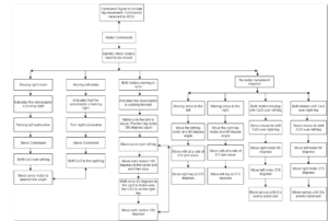
Along with the interface matrix, each project group is required to design a cable tree diagram which is another visual presentation of the system block diagram but with more details regarding the connection types; the wire lengths and also the gauge sizes. The cable tree diagram that has been provided below is based on the system block diagram and follows the same format and layout. This diagram was made possible through draw.io which served as the tool to design our diagram.

4

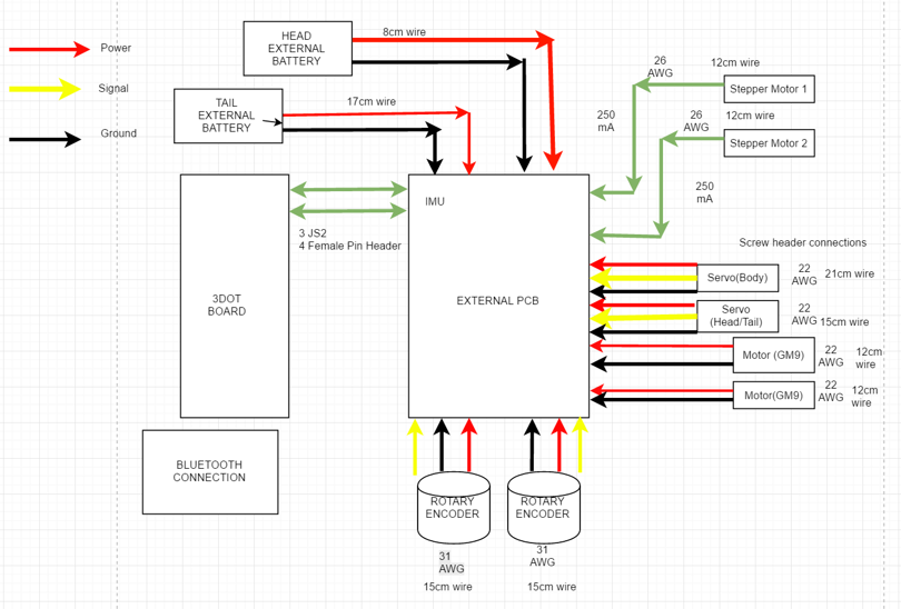
Diagram 1: Cable Tree


Conclusion


These diagrams that have posted above in this current blog post are the cabling diagram and interface diagrams. Both of these documents from above were previously presented during our presentation for the critical design review. Subsequently they have been revised to ensure that the velociraptor group produces excellent documentation materials.


Resources


[1] https://drive.google.com/file/d/0BzIcuzRpcmk4S252NEc5Sld5MU0/view

Fall 2016 Solar Panels: The Solar Panel Sandwich (the “Encapsulation”)

By Ridwan Maassarani (Design and Manufacturing)

Approved by Inna Echual (Project Manager)

Table of Contents

Introduction

In order to secure the cells onto the panel, one must consider the way of “sandwiching” the cells onto place. A rubber substrate was used for insulating the solar cells from the aluminum sheet. Here, I will review the “sandwich” method of encapsulation.

PV Back Sheet [1]

The first substrate considered was PV Back Sheet, which can be bought from aliexpress. This could reduce the thickness of the overall layers and, as explained by Dunmore, a supplier of solar panel material, “the PV back sheet is a photovoltaic laminate that protects the PV module from UV, moisture and weather while acting as an electrical insulator. DUN-SOLAR™ PV back sheets are available in a variety of constructions for both traditional rigid PV modules, like the one shown above, as well as thin film PV modules and solar power concentrators.”

EVA Layer [1][2]

Next, there’s the EVA layer, and according to Dunmore is a “thermoplastic containing ethylene vinyl acetate which is used to encapsulate the photovoltaic cells.” EVA encapsulation might not be the way to go since it needs to be heated which renders the cells inaccessible. And the cells need to be serviceable as part of our project requirement. For our panels, I took a couple of sticker paper and laser cut individual square cut outs to place each cells in its cavity and then when the acrylic is attached, there would be not visual gap between the cells and the acrylic. This did not work since I did not make my sticker paper thick enough. I modeled the shape I needed using Solidworks to ensure every cell in our current design had a cavity to sit in. Then I generated the dxf file that would then be used by the laser machine to cut the sticker paper, as shown in Figure 1.

sticker

Figure 1: Sticker Paper

Then comes the EPE insulations which is an extra layer of insulation, protecting the PV cells from being damaged from additional voltage seeping into the cells and damaging them.

Finally, there’s glass, which was substituted with acrylic in our final product which based on a PDF document written by Arkema, a leading specialty chemicals and advanced materials company says that it transmits 92% of the suns light striking it at the perpendicular.

The entire sandwiching process can be seen in Figure 2.

sandwich

Figure 2: Sandwich Process

References

[1] Solar Back Sheet: http://www.dunmore.com/products/solar-back-sheet.html

[2] Eva Film: http://sinovoltaics.com/learning-center/materials/ethylene-vinyl-acetate-eva-film-composition-and-application/

[3] Plexiglass: http://www.plexiglas.com/export/sites/plexiglas/.content/medias/downloads/sheet-docs/plexiglas-optical-and-transmission-characteristics.pdf

Fall 2016 Velociraptor (W): Software Block Diagram

By Gifty Sackey (Mission, Systems, and Test)

Approved by:

– Lam Nguyen (Project Manager)

– James Lee (Division Manager for Mission, System, and Test)

Table of Contents

Introduction

The purpose of this blog post is to discuss and summarize the control functions that will be required in the programming of the robot. It will cover the software block diagram and introduce the set of tasks that the software had to accomplish. For the mission profile for the Velociraptor shall participate in the Game Arena and statically walk. The software flow chart that is attached, allows users to see how the Arxterra firmware will be modified and the programmed through the 3DoT board.

Software Block Diagram – (Old)

software-block-diagram-old

Diagram 1. Software Block Diagram

Software Block Diagram – (Updated)

software-block

Diagram 2. Software Block Diagram Updated

In the event that a command is sent via Bluetooth from the ArxRobot App, the command decoder and handler functions will be executed on the action. The software block diagram, allows readers to gain an insight on the inputs that the robot functions will be taking as well as the outputs. For this blog post, I will be explaining in detail how the velociraptor will perform when the right motor is the only thing allowed to move. When the velociraptor is being moved and controlled by a single motor, the velociraptor is making a turn. In the case of the right motor moving, this indicates that the velociraptor is turning left. A turning left subroutine code would then be initiated as well as servo commands. In order for the velociraptor to be able to make a complete turn, it would have to shift its center of gravity over the left leg by moving the servo 30 degrees from the neutral position so that the it is balanced over that specified foot.

For the velociraptor to achieve static walking, the control codes will be designed such that both motors will be moving out of sync. While both motors are moving out of sync, as engineers, we need to make sure that the revolutions per minute (rpm) should have different values for both motors while having both legs be 180 degrees apart. The servo would then be moved over the left leg but then both motors would be required to move 180 degrees at the same rpm value and then stop in order to complete a step. At this point, the velociraptor needs to maintain balance so it needs to shift the servos at a 60 degree angle in order to ensure the center of gravity is on the right leg. At this point, the robot must move both motors 180 degrees forward to complete a step. The robot would then repeat this process until a different command is called from the Arxterra application.

Fall 2016 Velociraptor (W): Validation and Verification Test Plan

By:

– Lam Nguyen (Project Manager – Velociraptor Wednesday)

– Paul Ahumada (Project Manager – Velociraptor Thursday)

– Gifty Sackey (Mission, System, and Test Engineer)


Introduction


The final validation and verification test plan was written to verify the requirements for the Velociraptor through the Validation and Verification Matrix.

Link: verification-and-validation-matrix

Verification & Validation Test Plan

Below are the validation and verification test plan that supports our level 1 and 2 requirements.

Link: verification-and-validation-test-plan-results

Fall 2016 Velociraptor (W): Center of Mass

By Aaron Choi (Manufacturing Engineer)

Approved by

-Lam Nguyen (Project Manager)

-Tim Haddadian (Division Manager for Manufacturing)

Table of Contents

Requirements

Level 2-10 The center of gravity on the axis of the head and tail shall be controlled by one servo while being placed over the foot

Introduction

The center of mass is crucial for the design of the Velociraptor. To fulfill the Level 2-10 requirement, the center of mass should be placed over the foot. To observe the center of mass, the SolidWorks model of the design is required.

Library of Density

To observe an accurate center of mass, the mass of each observed through SolidWorks. There is no direct way to edit an object’s center of mass. However, a material can change its mass through density. Figure [1] below shows the example of a custom density for a material. The mass was either given from datasheets or weighed through a weight scale. The GM9 [1] and SG90 [2] mass were given through their respective datasheet. The volume of each Solidworks file were observed through the Measure tool in Solidworks. Then the density was calculated with mass divided by volume. Then the units were converted to match kg/m^3. Certain materials contained their density, such as Birchwood [3].

figure-1

Figure [1]

Density of the 7.4 Li-Po battery.

table-1


Table[1]

The table shows the density used for each custom material in Solidworks.

Center of Mass of Velociraptor

From the custom library of densities, the accurate center of mass was found. Then moving the head and tail through Solidworks, the head and tail were shifted at an angle. The angle found was 35 degrees.

figure-2
Figure [2]

The black and white dote represents the center of mass.

Conclusion

In conclusion, the center of mass was observed over the foot at 35 degrees. This was calculated by subtracting 65 degrees, found through Solidworks, to 90 degrees. This meets the Level 2-10 requirement.


Reference

[1]  https://solarbotics.com/product/gm9/


[2]  http://www.micropik.com/PDF/SG90Servo.pdf


[3] http://www.engineeringtoolbox.com/wood-density-d_40.html