

Written by: Forrest Pino
Approved by: Carolina Barrera
The bicep – also known as the bicep branchii, is a muscle that lies in the upper arm between the shoulder and the elbow. It’s is a structural part that offers sturdiness and strength to the overall upper-arm system. The overall arm works as a lever where the weight of the forearm and the hand are the load, the elbow is the axis or fulcrum and finally the bicep muscle when flexed is the force that will executing a work.
The following is a development write-up of the bicep design done by the manufacturing engineer in the Prosthetic Arm team, Forest Pino.
The first design concept arose from simple measurements and initial brainstorming. I measured the length of my arm and tried to develop a design that would be an adequate length and shape.
The concave nature of the lower section of the bicep was developed after studying other prosthetic arm projects with similar features. The concave feature allows for the forearm to rotate about the semi-circle at the bottom of the design.
A perforated design was conceptualized due to its ability to maintain structural integrity while reducing weight. The prosthetic arm and its various sections are limited by weight so any gaps or features that can reduce the use of plastic will help with weight and cost of the project.

Figure 1 – Lateral structure. First iteration of bicep
Triangular and trapezoidal features were added for strength and stability. The initial design did not contain any features that would helping with housing components. At the time, parts were not realized and the design served more as a stepping stone and base for further work.

Figure 2 – Design 1 Pre-Motor Mount
The cuts on the outer perimeter of the design were developed for braces that would be attaching and providing for structural integrity.

Figure 3 – Pre-motor Design Lateral Side
These trapezoidal cuts were made as a locking mechanism that would help pieces maintain position and provide for structural integrity. The largest side of the trapezoidal cut was planned to be the outer face of the bicep. This feature would allow interlocking piece to slide in only one direction.

Figure 4

Figure 5

Figure 6
Once a possible motor was selected, an area for mounting began to take shape. The extruded circular cut in the lower half of the bicep was planned to be the area where the motor would be mounted. The shaft of the motor would protrude outward toward the outer face of the bicep. In this design, the arm that would be developed would be on the right and where the gears would line on the outer side of the arm. Originally, the twos gears were thought to be interconnected by a pulley or chain. The possible sizes of the gears were not realized at this point and a cut made for the mounting of the forearm to the bicep could not be produced yet. Having gears on the inside of the bicep or residing between the arm and the body would not be feasible due to the size of the motor and possible interference. The gears were chosen to reside on the outer most part of the arm so that interference from the user would be reduced

Figure 7

Figure 8
The first assembly provided a base knowledge into how lightweight the initial design work was and how adding more plastic for the mounting of components may be necessary. The areas where the components may reside were exposed to the surrounding environment and a little more protection seemed to be necessary. The bars of plastic did not provide much confidence for stability and were eventually scrapped for ideas that utilized plastic more effectively.
After some deliberation, it was found that the previous height of our design was too tall. We wanted to follow a design that more closely represented the size of a prosthetic for an individual with an above elbow amputation. Previously, I had taken measurements from my shoulder down to my elbow. I aimed to shrink the design while having the appropriate space for the components as well as to not construct a bulky, uncomfortable design.

Figure 9
After some research on gear availability, it become known that we had one option for purchasing gears or we would be developing a printable gear system. Originally, we visualized that the gears we would utilize would be connected by a chain or pulley but that was not necessarily the case.
The gears that were idealized for the system were larger than we had anticipated and a pulley or chain was not needed. The center-to-center distance of the two gears was more than previously thought so the design was adjusted in order to accommodate and support teeth-to-teeth interaction for the purchased gears.

Figure 10
Interlocking pieces with bored holes for fastening were the major additions to the design. They were added to improve structural integrity.

Figure 11
Sections capable of inserts were added for structural stability. Pieces were constructed in a way that would allow them to slide into the sides of the bicep. Pins or screws were to be used to fasten the brace and side together. Initially, I thought the slots were beneficial for the design but they were not necessarily capable in real world applications. The printer that is available to us may not be able to handle the bridging that occurs here. The original size of the slots were 0.1 inches (2.54 mm) and the printer does not provide infill to a design unless the print is at least 4 mm thick. This meant that the braces that would be printed for this design would only have a shell with minimal plastic making up the interior.

Figure 12
The area in which the motor would be mounted was raised compared to previous designs. This was done to ensure that the motor would be mounted to an area that would be structural sound and capable of supporting a suspended motor.

Figure 13
Trapezoidal cuts with raised planks to add addition support. The two interlocking pieces can be fastened together through the matching and aligned holes.

Figure 14
A shelf feature was added to the inner side of the wall of the bicep. The purpose of the shelf was to house or suspend the PCB above the motor. Allowing the PCB to be suspend inside the bicep gives the PCB less opportunity to overheat.

Figure 15
The first attempt at creating and mating two gears was not successful. I tried to utilize the premade gear in SolidWorks while also trying to apply the same properties to the larger gear. The gears did not provide a smooth motion and their movements interfered with one another.

Figure 16
Some troubling aspects of the design surfaced once real-world movements were considered. The degrees of freedom that were chosen for the operation were not possible with this design. This meant that alternations were needed in order for the bicep to not interfere with the forearm movement.

Figure 17
The newest design made it capable of providing the full degrees of freedom and thicknesses of vital housing areas were increased for adding stability.

Figure 18
Depending on the battery that is utilized, the battery may extend outward past the brace on the back of the bicep design. A transparent or detachable covering by be placed over the opening so that the battery will be covered and the customer may have access.

Figure 19
The top sectional area will house the battery we decide to use and the spacing that was created will allow for it to hold any of the batteries we have selected. The triangular gaps in the battery shelf will be utilized with Velcro to house the selected battery. The top most brace was left with a perforated areas due to our planning in the mounting phase. It is unclear on how the bicep will be connected to the mount but the untouched surface leaves us with possibilities. Holes may be added in later designs before printing or may surface afterwards with the use of a drill. The thickness of any part of the design was constructed to be at least 4 millimeters (0.1575 in) due to the printer’s inability to provide infill under that thickness.
The mass analysis of the bicep structure with the material set to ABS plastic is 1.23 lbs. with a volume of 33.41 cubic inches.
By using the estimated volume and the density properties found from a provide data sheet, another mass estimate can be determined.
PLA – density properties from NatureWorks LLC datasheet

Gears were designed to resemble the gears that were available for purchase. The properties of the gears that were available for purchase were on the company website and these aspects were utilized in equation driven properties in SolidWorks.
The angle between the plane that resides on the inside of the forearm and the top brace is 59.72 degrees when the arm is fully extended backwards.
The angle between the plane that resides on the inside of the forearm and the top brace is 60.72 degrees when the arm is fully extended forward. The measurements show the full degrees of freedom being 180 degrees for the latest design.
By Inna Echual (Project Manager)
The team received the PDR debrief from meeting with the customer and the president. A concern of theirs was that our mission profile presented during the PDR (1) was not updated as the Chassis group in the Thursday class had changed their course to an area with a stronger WiFi signal and (2) was representative more of the Chassis group’s mission profile instead of ours.
Because of the two reasons, the team then developed a new mission profile which will clarify the confusion present in the current one.
The project will be demonstrated by charging the pathfinder’s battery using solar panels in order to completing the course defined by the Spring 2016 AdBot rover, as shown in Figure 1. This course is on the California State University, Long Beach campus, specifically in front of the University Student Union building and will be conducted at night for better operation of the LiDAR sensor.

Figure 1: Spring 2016 AdBot Rover Route
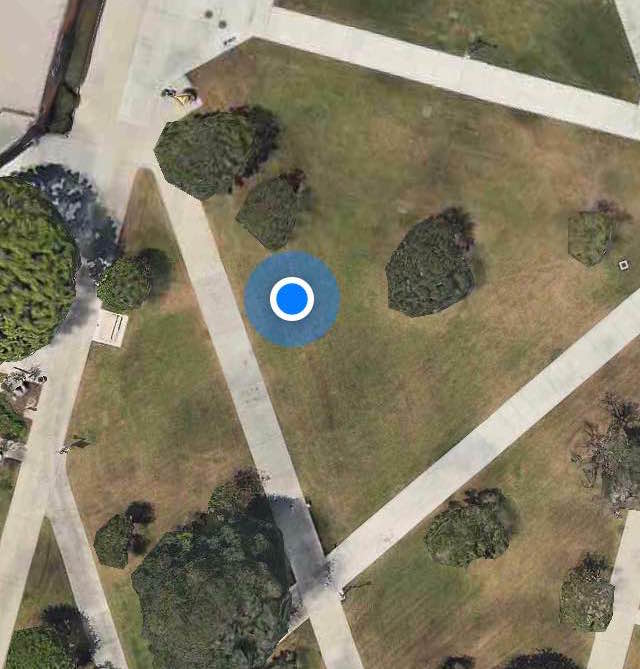
The project will be demonstrated by parking the Pathfinder in the Central Quad on California State University, Long Beach located at 33°46’40.7″N 118°06’48.9″W. In addition to the location near the defined travel course, the parking spot was chosen as it had low traffic and free of shading. The parking spot is indicated in Figure 2.

Figure 2: Fall 2016 Parking spot
By Ridwan Maassarani (Design & Manufacturing)
Edited and Approved By Inna Echual (Project Manager)
Objective: One of the most important components of our project is to define the folding mechanism that will allow us to achieve the cocooning requirement. This study will showcase the mechanisms we considered and which of the ones research was chosen.
Video 1: Rack and Pinion Folding Mechanism
This idea was brought up through a YouTube search on “folding mechanisms,” resulting in the rack and pinion method in the video above. The folding is accomplished by sliding a rack back and forth and spinning a spur gear placed at the hinges of the panels. This configuration was created to fold t-shirts but I found this video to be very helpful.
For doing this method, the rack would have to be suspended from underneath the panel because doing a two-layered panel configuration like the video would be unfeasible as it would result in more materials, adding cost and weight. Taking those factors into account, it was additionally determined that is method is not the best for folding our panels since having the rack be suspended underneath could prevent the side panels from going -15° (for example) when the panels articulate to track the sun.
However, this video inspired us to consider attaching a gear to the pin of a hinge and to consider a gearing mechanism to do the folding of the panels.
Video 2: Linear Actuator Folding Mechanism
This method of using a linear actuator was both found by doing the same YouTube search and as suggested by Professor Hill. Though the linear actuator would provide enough force to push open our panels despite its weight, we had many concerns:
Therefore, we determined that this method was not the best and we continued to research further on folding mechanisms.
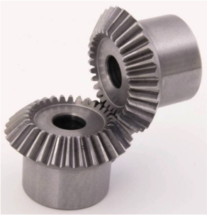
Figure 3: Bevel Gear
Through we are not considering rack and pinion method for folding, we were inspired by the gear to incorporate a bevel gear into the mechanism to lift the panels into position. One bevel gear would be fixed to a rod extending from piano hinge and that pin of the hinge will be welded to one side of the hinge on the panel that needs to be lifted.
The main concern is the panel could not be kept at a specified angle and the motors would have to be constantly turned on to hold the panel at that angle. After the Iterative design process and additional research, the worm gear was considered for its self-locking feature.

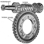
Figure 4: Worm Gear
The worm gears are considered because of power transfer due to the effectiveness of the two gears meshing. One appealing feature is that they are self-locking, meaning that the gear cannot drive the worm. For example, when the weight of the panels exerts torque, the motor is not affected; if the panels are going from 90° to 180° there won’t be load exerting torque on the stepper motor. Another feature is that they occupy less space which would declutter the design and reduce overall mass.
The most important advantage is that they are known for being used for speed reduction and increasing torque. This will be extremely helpful when doing a lifting action for our sun articulation.
A custom bracket shall be designed to allow to mount the stepper motor low to the ground.
Take the right back panel for example:
Weight of panel on SolidWorks using 6061-T6 Aluminum = 165 grams
Distance
For safe measure a weight of 250 grams will be used.
So, a motor with a torque of 23 oz.in or higher will in theory be able to lift the right pack panel.
As stated earlier, one of the advantages of worm gear is having higher gear ratios. For this example, a 30:1 gear ratio will be examined.
Motor – NEMA 17-size hybrid stepping motor with a torque of 44 oz.in
Motor Torque x gear ratio = torque at the hinge
This is more than enough to be able to lift the panels.
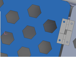
Figure 5: Lever Arm from Axis of Rotation


By: Nick Lukin (Design and Manufacturing Engineer)
Table of Contents
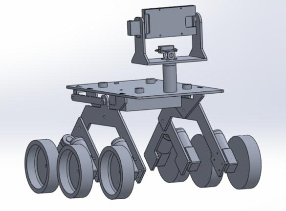
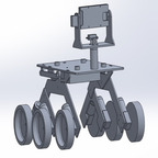
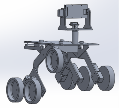
Figure 1: Overall Mechanical Design
The mechanical design of the Pathfinder utilizes many parts and sub-assemblies in order to achieve all the requirements associated with the overall design. In order to achieve the level 1 requirement of being able to successfully traverse a pre-determined course on campus it was necessary to utilize a proper suspension system. It was also necessary to completely rebuild the pan and tilt smart phone holder in order to fit a Samsung Galaxy S7 edge. The suspension design utilizes a rocker bogie suspension system very similar to the one used on the Spirit rover. Below is a description of the overall mechanical design including all of its assemblies and sub-assemblies.

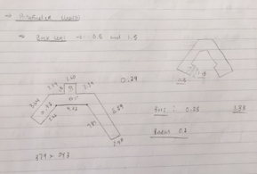
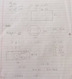
The Spring 2016 Pathfinder was used as a base reference in order to come up with a usable overall design. Each part was measured and then modeled in solidworks in order to come up with working parts and assemblies. The pictures above shows some sketches of the various parts that needed to be measured, modified and then modeled. It was necessary to change the overall geometry of the suspension and platform in order to achieve some of our desired design outcomes such as wheel clearance and lower center of gravity.

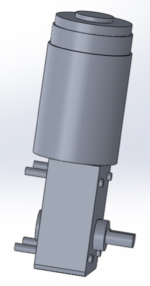
The above pictures are models of the base servo mechanism and the actual motors that are used. It was necessary to properly model these in solidworks in order to get a more accurate overall model of the pathfinder. The base servo mechanism mounts the servo that controls the pan motion of the smart phone holder. Adding the motors gives an accurate measurement of the width of the Pathfinder.
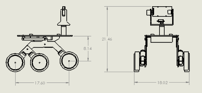

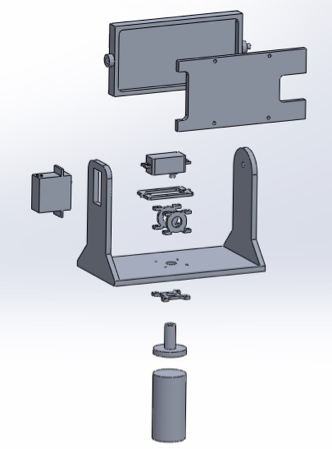
The above pictures show a 2-D drawing as well as a 3-D exploded view of the Pathfinder design. The overall dimensions of the design can be seen below.
Height: 21.6 inches
Width: 18.02 inches
Length: 23.60 inches
Floor to Top panel: 11.14 inches
The overall design can be broken into two basic sub-assemblies. These include the rocker bogie suspension system and the pan/tilt smart phone holder. Descriptions of these sub-assemblies can be seen in the next sections.
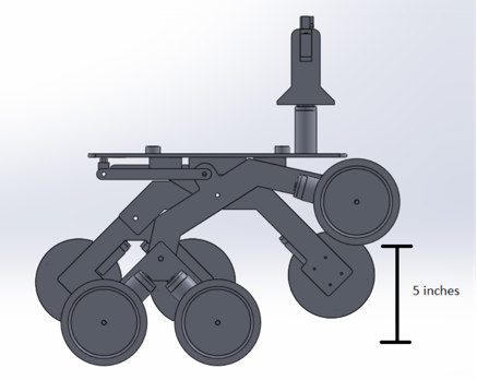
The rocker bogie suspension system that was utilized in our design is very similar to the one used on the Mars Spirit rover. This suspension system is good for uneven surfaces and requires no springs or dampening mechanisms. Each wheel can move up and down independent of one another. Another benefit of this suspension system is that the main body stays straight and upright while going up of down steep surfaces. This creates good weight distribution and helps prevent the Pathfinder from tipping over. The overall wheel clearance of the suspension system was designed to be 5 inches due to the fact that it will need to go upstairs that are about 5 inches tall. The diameter of the wheels is 6 inches, therefore the height of the Pathfinder from the ground to the bottom of the base platform is 11.14 inches.
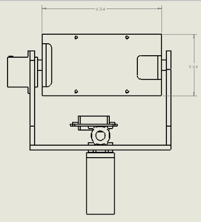
The pan/tilt smartphone holder is designed to hold a Samsung Galaxy S7 edge. The dimensions of the phone are 5.94 x 2.86 x 0.30 in. The holder case was designed to have the following dimensions: 6.34 x 3.26 x 0.7 in. The thickness of the case will be 0.2 inches which will allow for the phone to be fully covered. The front cover plate was designed to have cutouts in the appropriate locations. The cutouts can be seen in the picture above. These cutouts are for the camera and for the antennas in the phone. It is necessary that these do not get covered in order to obtain good signal strength. The pan/tilt servos will be able to move 180 degrees in both directions.
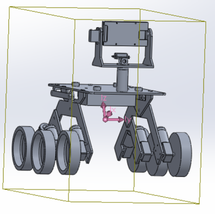
The goal of the design was to get the center of mass as low as possible. The picture above shows the center of mass in purple. The previous design had a center of mass the was above the main pivot point of the rocker bogie front arm. The design focused on lowering the center of mass below the pivot point. This was achieved by redesigning the top platform and lowing it an inch. Lowering it an inch meant that the clearance would also be 1 inch smaller which was a problem. This was solved by making the rocker bogie arms one inch longer. The electrical box and battery will also be mounted on the bottom too which helps make the center of mass lower.
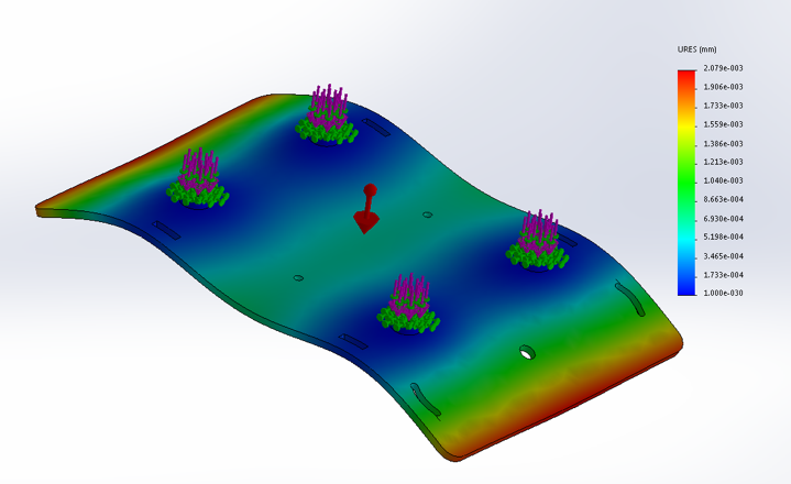
The top panel was analyzed to see how it would react to an outside force being applied to it. The top panel will carry the majority of the load which includes the Solar Panels, the Pan/Tilt Smartphone Holder, the Batteries and the Electronics. The above photo is an exaggerated simulation on how the panel may deform under certain stresses.

It will be necessary to properly interconnect the chassis to the solar panel assembly. The picture above shows the interconnection mounting points and the dimensions. 4 connection points will be used for optimal stability. These connection points will be raised pads with holes drilled through them. The solar panel assembly will then align with the holes and quick release pins win hold them in place. This will allow for quick removal of the panels.