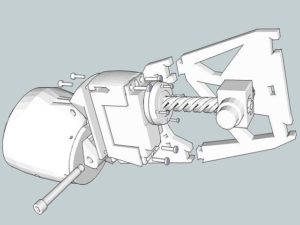
2016 Fall Velociraptor: Preliminary Project Plan

Paul Ahumada – Project Manager

Robert Licari – Systems Engineer

Kevin Armentrout – Electronics and Control Engineer

Victoria Osaji – Manufacturing Engineer

Table of Contents

Work Breakdown Structure

By Paul Ahumada

wbs-min

The WBS represents the job description tasks that members must fulfill. The three engineers are separated into their own divisions and handle their task for the Velociraptor. The tasks throughout the semester are specifically shown in the calendar view in the Top Level Schedule section.

Project Schedule

Top Level Schedule

By Paul Ahumada

project-top-schedule-min

The schedule is spread out for the semester with start and due dates for each task. These dates refer to a schedule provided by the customer. The Velociraptor project should follow the schedule to remain on track. Experiments and tests may be added as they are discovered and increase the task load.

The calendar provides a visual with names associated with each task. The person assigned to that task is responsible for its completion.

Calendar View Of Scheduleschedule-min

System/Subsystem Level Tasks

By Paul Ahumada

These tasks are shown in the Top Level Schedule. On the calendar layout, names are associated with each task. These tasks must be fulfilled by their associated team members. If there are no members listed, then the team as a whole must complete the task.

Burn Down and Project Percent Completion

By Paul Ahumada

burndown-schedule

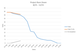
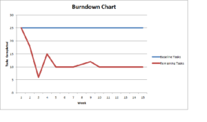
The Project Burn Down shows how many tasks are left that the Velociraptor group must complete by the last day of the semester. The tasks we compare to are the remaining tasks in the Top Level Schedule. These tasks may increase as new experiments and tests are discovered. The Percent Completion is on a scale of 0-50 so it can be included on the same graph of tasks remaining.

System Resource Reports

By: Robert Licari

Mass Report

mass-report

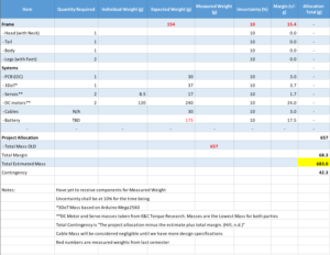
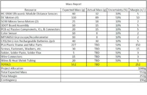
The mass needs to be as close to 657g as possible to meet initial torque calculations (done by E&C). Currently the estimated mass is at 706g with a contingency of 21.6. Assets that were used in this calculation come from the previous semester as well as the initial torque calculations. From the previous semester, we have our mass allotment of 657g as well as an overall frame mass of 154g. For our purposes, the frame mass shall be the total mass of the mechanical structure of the velociraptor without anything listed under the “Systems” category. Systems includes anything that will contain our control modules, battery packs, and any cables outside of the 3DoT board and the PCB motor controller. The battery mass was taken from last semester as a placeholder. We should expect the battery to be of equivalent or less mass than last semester. An allotment of 60g divided between the cables and the Motor Controller PCB have also been given as placeholders and will most likely alter based upon final design choices. Due to the nature of the design changes, this is only a preliminary mass resource report and is subject to change.

Power Report

power-report

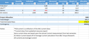
The power resource comes from four basic factors that draw current from our supply source. Supply source will be defined as the battery on the 3DoT board as well as an external battery source. The 3DoT board will consist of the Atmega32U4 microcontroller, the HC-10 Bluetooth module, as well as the boost converter and was estimated at 110mA average by spiderbot. The motors will be separated into the server motors and the DC motors. Current draw from the servos was taken from the “Actual Current” measurement from last semester, and the draw of the DC Motors was taken from the average current draw from the initial torque calculations. The PCB design has changed, so the current draw is minimal due to last-minute design changes. Due to the nature of the design changes, this is only a preliminary power resource report and is subject to change.

Project Cost Estimate

By Paul Ahumada

cost-report-min

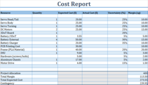
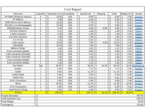
The Cost Report provides an estimate to what the expected costs will be. The previous semester had there project cost $257.48. There project had $443.76 allocated for the frame and had an actual cost of $5.00. There reports show that the robot was not made 100% of aluminum and used a combination of aluminum and PLA to reduce costs described by their mass reports. The cost report shown for 3rd generation shows an expected cost of $273.55 and is increased because of the margin. Previous semesters requested $400.00 and our increased margin brings us to $387.05. Numerous components were looked at and are included in the citations.

Citations:

  1. http://web.csulb.edu/~hill/ee400d/Lectures/Week%2005%20Project%20Plans%20and%20Reports/c_Generic%20Schedule.pdf
  2. https://www.servocity.com/hs-5065mg
  3. https://www.servocity.com/hs-65hb-servo
  4. https://www.servocity.com/hs-65mg-servo
  5. http://www.ebay.com/itm/Torque-Digital-Metal-Gear-Servo-Motor-for-RC-Robot-Helicopter-Airplane-Car-Boat-/222246871400?var=&hash=item33bef22168:m:mq1v5yVeOUDRTVVJUVjh70A
  6. http://www.ebay.com/itm/AE-Team-Associated-1-10-ProSC-ProLite-4×4-XP-DIGITAL-DS1903MG-STEERING-SERVO-/400948939305?hash=item5d5a6b4a29:g:j1MAAOSw0UdXqeLU
  7. http://www.robotshop.com/en/hitec-hs422-servo-motor.html
  8. https://www.arxterra.com/fall-2016-velociraptor-th-preliminary-design-document/
  9. https://www.google.com/search?q=pla+material&ie=utf-8&oe=utf-8#q=pla+material&tbm=shop&spd=8876641036563277883
  10. https://www.google.com/search?q=pla+material&ie=utf-8&oe=utf-8#q=pla+material&tbm=shop&spd=8876641036563277883
  11. http://www.homedepot.com/p/MD-Building-Products-24-in-x-36-in-Plain-Aluminum-Sheet-in-Silver-57794/202091743
  12. https://www.servocity.com/81-rpm-mini-econ-gear-motor
  13. https://www.servocity.com/90-rpm-micro-gear-motor-w-encoder
  14. https://www.servocity.com/90-rpm-micro-gear-motor
  15. http://www.batteryspace.com/A123-System-Nanophosphate-LiFePO4-18650-Rechargeable-Cell-3.2V-1100mAh.aspx
  16. http://www.batteryspace.com/smart-charger-3-0a-for-3-2v-lifepo4-battery-pack.aspx
  17. http://www.all-battery.com/TenergyLiFePO4BatteryCharger-01369.aspx?utm_source=GoogleShopping&utm_medium=GDF&gdffi=fb520bc42d4e46cbab702234d35f7d38&gdfms=58521D8DE97640DEAF38BED2760D36D6&gclid=CjwKEAjwjqO_BRDribyJpc_mzHgSJABdnsFW5P8tGT10YF5GFBHJeBKOgnXMOOc1RIUaGDwV8nozwhoCQvjw_wcB


Preliminary Project Plan – Prosthetic Arm (Fall 2016)

WORKDOWN BREAKDOWN STRUCTURE

The following Work-down Structure is the second iteration we got after we organize the potential schedule for the semester.

wbs-second-iteration

Figure 1 – WBS 2nd iteration

PROJECT SCHEDULE

The project schedule was done to give a basic idea to the group on the timing framework, and to work as a reference to know if the tasks are being done in a timely manner.

From the schedule we conclude that regardless of the video-taking that we are going to be doing to provide documentation about the project, we will spend major part of the project performing experiments on the arm system, and making sure it works as a whole.

The schedule for the project of the Prosthetic Arm is provided in HERE

SYSTEM RESOURCE REPORTS

Mass Report

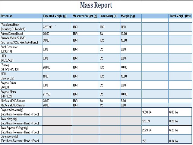
For this initial mass resource report for the Prosthetic Arm project, the total expected weight of internal components (inclusive of an estimated 5 lbs from the Prosthetic Hand and 21 fl. oz. drink combined, per our L2-3 requirement) totals to 6.23 lbs, with a margin of 0.26 lbs.   Given a required capacity to lift up to 6.83 lbs, the current report meets the requirement with a contingency of 0.34 lbs.  The measured weight of the majority of our components is to be resolved, as we have not yet received many of the parts and validated their actual weights on a scale, however given margins and uncertainty, the actual weights are predicted to be lower than the expected weights.

mass-report

Figure 2 – Mass Report

Power Report

In this initial iteration of the power resource report for the Prosthetic Arm project, the total expected current totals to 3242 A, inclusive of supplying the Prosthetic Hand with an estimate of 2A on 12V and 1A on 5V.  The total margin for the current sums up to 0.840 A, with a remaining contingency of 0.418 A.

power-report

Figure 3 – Power Report

Cost Report

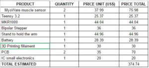
This first iteration of the cost resource report for the Prosthetic Arm project shows an expected project cost of $286.48, with a margin of $63.87 for the electronic components of the project.  With respect to these estimates, the contingency amounts to $149.65, which will be allocated to the manufacturing components specified in the overall Project Cost Estimate.

cost-report

Figure 4 – Cost Report


Cost

CA Tax Rate – Long Beach, CA

Wire

Buck Converter

14.8V Li-Po Battery

UPS Ground Shipping

Teensy 3.2 (Cost)

Stepper Motor Driver

Stepper Motor

Myoware EMG Sensor (Cost)


Mass/ Power

Buck Converter LT3971A (10-Lead MSOP Packaging Weight)

LDO

14.8V Li-Po Battery

Teensy 3.2

Stepper Motor (PHI – 3321)

Myoware EMG Sensor (Weight)

Stepper Driver

Wire

PROJECT COST ESTIMATE

The project estimate is based on the budget and materials that we have purchased and looked at. It provides margin and it confirms our estimate provided previously in the Preliminary Design Document.

budget-allocation

Figure 6 – Project Cost Estimated

Fall 2016 BiPed : Preliminary Project Plan

Gifty Sackey (Project Manager)

Brandon Perez (Systems Engineer)

Ryan Daly (Electronics and Controls Engineer)

Ijya Karki (Manufacturing Engineer)

Table of Contents

Work Breakdown Structure

Gifty Sackey (Project Manager)

The Work Breakdown Structure (WBS) diagram, shows the responsibilities of each BiPed group member. A top level view of the job requirements can able to found in the product breakdown structure provided below. In each division of the product, readers are provided with a detailed explanation of what each team member will be responsible for their part.

final-wbs-tree-diagram

Figure 1 : Work Breakdown Structure

Product Breakdown Structure

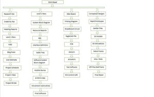
The Product Breakdown Structure (PBS) outlines what products are required to be designed by each group over the course of the semester. The PBS is broken down into a consecutive algorithm in order to ensure a successful completion of the product. Note that the blocks, containing what is produced, are not limited to intervention by other team members. The block labeling allows for a broad overview of what each members responsibilities are without going into details of each product.

product-breakdown-structure

Figure 2 : Product Breakdown Structure

 Project Schedule 

The project schedule details the necessary work that needs to done to implement the BiPed. In addition to the schedule, a projected timeline of deadlines and dates can also be found. In the link provided, readers can find a visual presentation of what the proposed schedule for implementing the BiPed. ProjectLibre was the tool used to implement the schedule. By manipulating the dates provided, if we are able to refine and solidify our requirements early, it gives us more flexibility with our days for coding; validation tests and also unforeseen events.

https://drive.google.com/file/d/0BzIcuzRpcmk4T3ZYX20wUmlPUmM/view?usp=sharing

Burn down and Project Percent Completion

The project percent completion and burn down chart provides a visual representation of the tasks that needs to be completed for the BiPed. It also allows the team to know how much of the current work load has been done.

breakdown-chart

Figure 3 : Breakdown Chart

Project Cost Estimate

The Cost Report summarizes how much each physical part of our product will cost. Details about shipping are not included in each resource since they can be bundled in the same order when ordering multiple parts from the same vendor. Amazon has no shipping charges if the parts are picked up at our Amazon pickup location at our University. The Project Allocation was determined based off what Rofi, the previous BiPed cost to be initially built.

cost-report-2-1

Figure 4 : Cost Estimates

System Resource Reports

Brandon Perez (Systems Engineer)

Mass Report

The mass report summarizes an expected mass of our individual physical products of the BiPed. Most of the items were easy to determine since details about most electronic components contain a mass value on their spec sheets or on their vendor’s website. The PLA Platsic mass was determined based off what the previous BiPed weight. All “Actual Mass” values will be determined when obtaining the physical parts. Project Allocation value is an idealistic estimate of what we think the BiPed’s mass should be limited to.

mass-report-2

Figure 5: Mass Report

Power Report

The power report summarizes how much power each electronic component will be consuming. No values shall be needed for the mechanical hardware since power consumption due to kinetic energy will only reflect in the power consumed by our electromechanical devices such as our dc motors and servos. Project Allocation value was determined based off how much constant power our two batteries would supply over the course of an hour.

power-report-5

Figure 6 : Power Report

Fall 2016, Preliminary Design Documentation

Sabina Subedi – Project Manager

Adan Rodriguez – Mission, Systems and Test

Jose Alcantar – Electronics and Controls

Nicholas Lukin – Design and Manufacturing

Table of Contents

Review of Literature

By Sabina Subedi, Project Manager

Level 1 requirements for the Pathfinder from Spring 2016 were reviewed and analyzed per the requirement evaluation rubric provided below.

Requirement Evaluation Rubric:

  1. Is the requirement, Quantitative, Verifiable, and Realizable?
  2. Is the requirement located at the correct level (1 – Program/Project, 2 – System/Subsystem)
  3. Is the requirement response to a higher level requirement or customer’s objective (Requirement Flow Down)? Is the linkage clearly defined?
  4. Does requirement provide links to source material?
  5. Does the requirement move the design process forward?
  6. Are equations used to calculate a requirement provided and are answers correct?
  7. Is language in the form of a requirement?

 Figure 1: Review of requirements from Spring 2016

Program Objectives / Mission Profile

By Sabina Subedi, Project Manager

Program Objective Statement

The Pathfinder is an autonomous rover that is self-sufficient using solar panels. The design of the Pathfinder is inspired by the twin Mars rovers “Spirit and Opportunity.” The Pathfinder will utilize navigation waypoints on Arxterra control panel to traverse through the defined course, articulating ultrasonic range finders and LiDar sensor for obstacle avoidance. Digital slip differential will be implemented for unmanned turning of the rover during it’s course. In order to save battery, the Pathfinder will have sensors that will send signals to the motors to stop the wheels from spinning under no load conditions.

Mission Profile

The mission for the Pathfinder is to complete the same course defined for Spring 2016 AdBot. “The mission profile will be a test course consisting of the 9 steps in front of the USU building, then the concrete path clockwise leading down some inclines back to the bottom of the stairs.” (Spring 2016, AdBot Blogpost) The Pathfinder shall complete its mission in one evening.  The pathfinder shall conduct its mission at night for better operation of the LiDar sensor.

Requirements

Program/Project (Level 1)

By Sabina Subedi, Project Manager

  1. The pathfinder shall be autonomous, demonstrating GPS navigation mode on Arxterra
  2. The pathfinder shall avoid obstacles articulating Ping Ultrasonic Range Finder and a LiDAR sensor
  3. The pathfinder shall implement digital slip differential for turning, i.e., inside wheels turn at a different speed than the outside wheels while turning
  4. The six wheels shall be on a rocker bogie suspension system to allow the Pathfinder to traverse through rough terrain and enable mobility
  5. Each wheel shall have its own motor in order to be able to be controlled independently
  6. Wheels under no load condition shall stop spinning in order to conserve power
  7. The physical design of the Pathfinder shall mimic the Spirit and Opportunity rovers.
  8. The pan and tilt system shall be modified to support an Android phone
  9. The pan and tilt system shall be sealed in order to protect it from weather conditions in December
  10. The Pathfinder shall explore the course defined by the AdBot rover. The mission shall be completed in 4 hours in the evening.
  11. The Pathfinder shall be completed by the last day of 400D course, December 154h, 2016

System/Subsystem (Level 2)

By Jose Alcantar, Electronics and Controls Engineer

  1. The Pathfinder shall use an Arduino Leonardo implementing the latest version of the 3DoT library. Due to customer request, the current Arduino Mega will be replaced with the Arduino Leonardo. The Leonardo will be programmed using the 3DoT library.
  2. The Pathfinder shall use GPS coordinates from its sensors to communicate position with the Arxterra app. This will allow GPS navigation and the use of waypoint navigation.
  3. For obstacle avoidance, a LIDAR sensor and two SeedStudio ultrasonic range finders (SEN136B5B) shall be implemented onto the design of the Pathfinder. The ultrasonic range finder will be able to detect the range of obstacles in front of the pathfinder from 3cm to 400 cm. The LiDAR sensor will be able to detect the obstacle itself, allowing the rover to maneuver around that obstacle. A trade off study was done prior to choosing this specific model of ultrasonic range finder.
  4. The design of the pathfinder shall resemble the Spirit and Opportunity rovers. The Spirit and Opportunity rovers are each 1.5 meters high, 2.3 meters wide and 1.6 meters long, and weigh about 400 lbs.
  5. Due to the removal of the Google Tango, the pan, and tilt platform shall be redone to accommodate solely an Android phone, specifically a Samsung Galaxy S7 Edge. The dimensions of the phone to be used are 9 x 72.6 x 7.7 mm (5.94 x 2.86 x 0.30 in). The phone weighs 157.6 g.
  6. The encasement for the Android phone shall be sealed to protect the device from outdoor conditions.
  7. This requirement will vary depending on the weather conditions on the day of the final demonstration in December. The forecasted load for the day of the final, December 15th, 2016, is partially cloudy with a high of 65 degrees Fahrenheit and a low of 47 degrees Fahrenheit. No rain is forecasted for that week. Historical average for the day is 67 °/47 °.
  8. In order for the Pathfinder to implement electronic slip differential 6-wheel drive, three separate VNH 5019 motor shields shall be used to allow the control of each independent DC motor. Testing will be done to find a suitable voltage ratio between the wheels to ensure slip differential turning.
  9. The ACS712 (SEN-08883) current sensor shall be implemented to get feedback on the amount of current passing through the load. This current sensor will allows us to measure load up to 5A of AC or DC current.

Source Material

The links below consist of sources that were used in developing the Level 2 requirements.

PINGER and Arduino:

https://www.arduino.cc/en/Tutorial/Ping

Ultrasonic range finder (SEN135B5B) Fritzing diagram:

http://fritzing.org/media/fritzing-repo/projects/3/3pi-robot-atmega-328p-and-ultra-sonic-range-measur/other_files/ULTRASONIC%20SEN136B5B.pdf

SeedStudio UltraSonic range finder and Arduino interface:

https://www.youtube.com/watch?v=y8ox5NPvcPc

SeedStudio Ultra-sonic range finder:

http://www.eio.com/p-40804-seeedstudio-sen136b5b-ultra-sonic-range-measurement-module.aspx

Ultrasonic Field of View test, Fall 2015 Pathfinder:

http://arxterra.com/pathfinder-ultrasonic-field-of-view-test/

 Specifications of the Spirit and Opportunity:

http://hobbiton.thisside.net/rovermanual/

Waypoint navigation on Arxterra:

https://www.arxterra.com/arxterra-now-supports-waypoint-navigation/

Performance of Arduino Leonardo:

https://www.arduino.cc/en/Main/ArduinoBoardLeonardo

Performance of LiDar Lite V2:

https://www.sparkfun.com/products/retired/13680

Weather Forecast for December 2016:

http://www.accuweather.com/en/us/los-angeles-ca/90012/daily-weather-forecast/347625?day=86

Spring 2016 AdBot Preliminary Design Documentation:

http://arxterra.com/preliminary-2/

Low Current Sensor:

https://www.sparkfun.com/products/8883

Preliminary Budget

The preliminary budget was created based on the new upgrades required to the existing rover in order to meet the new Level 1 and Level 2 requirements for this semester, Fall 2016. This budget will be verified by our customer before any parts are purchased. Therefore, the total estimated cost is subject to change.

Figure 2: Preliminary Budget for the Pathfinder, Fall 2016

Design Innovation

By Sabina Subedi, Project Manager

A brainstorming exercise was performed in order to come up with creative solutions to the problems found in the existing Pathfinder. Some of the problems with the existing Pathfinder were:

  • It cannot climb up the stairs. This problem occured because the weight on the existing rover is not distributed properly. It could be fixed by lowering the center of gravity. Possible ways of lowering the center of gravity include but are not limited to redistributing the weight on top of the chassis, or lowering the entire platform and pushing the wheels further back.
  • The rover draws excess current merely due to its weight. The weight could be reduced by milling excess metal off or by using lighter components. This could potentially increase the battery life.
  • The existing pan and tilt system is designed for a Google Tango and is controlled by two servo motors. The existing encasement a bulky design made out of plastic. The bulkiness of the design limits the Pathfinder in its range of movement and makes it harder to navigate. Possible solution to this problem is to design a new pan and tilt system to hold an Android phone and utilize stepper motors instead of servos to reduce bulkiness as well as increase functionality.

Systems/Subsystem Design

By Jose Alcantar, Mission Systems and Test Engineer

Product Breakdown Structure

pbs

Figure 3: Product Breakdown Structure

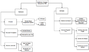
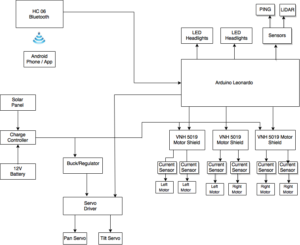
The product breakdown structure demonstrates the hierarchical breakdown of the products that will be used in the overall design of the Pathfinder chassis subsystem. At the highest level, the Pathfinder chassis subsystem splits into two separate main subcategories, the hardware and software aspect. The hardware consists of three subcategory items, the chassis, pan and tilt platform, and the Arduino microcontroller. The chassis subcategory was organized by first starting at the bottommost level, where the manufacturing engineer is responsible. This consists of the six wheels and six DC motors that will be installed onto the rocker bogie suspension system and ultimately onto the chassis. The pan and tilt platform is the responsibility of the manufacturing and electronics engineer. At the lowest level, the category consists of the Android device, motors for pan and tilt, and the two sensors. These bottom level components will be installed onto the manufactured pan and tilt platform allowing obstacle detection and platform control. The Arduino subcategory is the physical microcontroller used on the pathfinder. This category is further split into two categories, the motor shield, and Bluetooth module. The electronics engineer is responsible for these components. The use of the motor shields allow for DC motor control and the Bluetooth module allows for communication between Arduino and Android.

The other main subcategory is the software block. This block is then further split into other functions needed for the control of the pathfinder. The first sub component is the software-implemented control of the pan and tilt motors. The second component is the software controlled DC motors used for the wheels of the pathfinder. Third is the control of the LIDAR and Pinger sensors used for obstacle avoidance. The fourth component is the software integration for communication between Android and the Bluetooth.

Electronic System Design

By Adan Rodriguez and Jose Alcantar

System Block Diagram

By Adan Rodriguez, Mission, Systems and Test Engineer

Figure 4: System Block Diagram

Interface Definitions

By: Jose Alcantar, Electronics and Controls Engineer

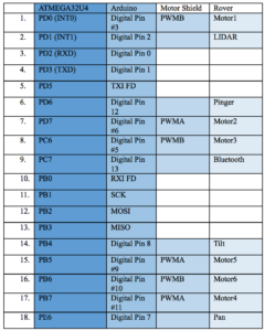
Figure 5: Interface Matrix

The interface matrix for the Pathfinder chassis subsystem tabularizes the pin connection layout of the electronic system. The embedded system is comprised of the ATMEGA32U4, Arduino Leonardo board, Motor Shield and finally sensors and actuators on the rover. The Arduino and motor shield use up some pins from the ATMEGA and in exchange get an extension in capabilities for the components used on the rover.

Fritzing Diagram

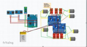
By: Jose Alcantar, Electronics and Controls Engineer

Figure 6: Fritzing Diagram 

Source Material

The following sources were used in developing the interface definition.

https://cdn.sparkfun.com/datasheets/Sensors/Proximity/lidarlite2DS.pdf

https://www.arduino.cc/en/uploads/Main/arduino-leonardo-schematic_3b.pdf

https://www.arduino.cc/en/Main/ArduinoBoardLeonardo

https://www.adafruit.com/product/1438

https://cdn-shop.adafruit.com/datasheets/TB6612FNG_datasheet_en_20121101.pdf

Mechanical Design

By Nicholas Lukin, Design and Manufacturing Engineer

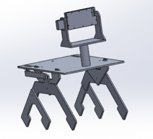
Overall Design

Figure 7 : Overall design of the new chassis

Figure 8: Exploded view of the new chassis

The above pictures are models of what the Pathfinder should look like in order to satisfy the level 1 and 2 requirements. In order to satisfy the mission objective of traversing the same course/path that was outlined for the “Spring 2016 Adbot” the Pathfinder will utilize a rocker bogie suspension system that is very similar to the design used on the Spirit mars rover. This suspension system gives the Pathfinder a wide and long stance allowing it to climb up and around obstacles such as rocks and stairs. The length from the front to the back wheel will need to be longer than the length of the base platform in order to produce a wide stance. This wide stance will prevent the Pathfinder from tipping backwards when going up steep surfaces. Many components will be mounted to the base platform such as the pan/tilt mobile case, solar panels, electronics box, battery and sensors. These components will be mounted in a way that will create even weight distribution on the base platform. This even weight distribution will also help the Pathfinder remain upright when going up steep surfaces. Using a rocker bogie suspension system and having even weight distribution will help achieve the goal of traversing the course.

Chassis Lightening

Figure 9: Rocker-Bogie Suspension system

In order to conserve battery life and limit the stress put on the driver motors the chassis will be made as light as possible. The suspension components of the current Pathfinder will need to modified in order to achieve this requirement. The above picture shows the suspension components and how they may look in order to achieve the lightest possible design. About half an inch may be cut off from the inside of the suspension legs. Stress simulations and calculations will need to be performed to ensure that the new lightened chassis can handle the load of all the components that will be mounted to the base platform.

Mobile Phone Pan and Tilt System Design

Figure 10: Pan and Tilt System design

The use of a Pan/Tilt mobile encasement is required in order to help the Pathfinder navigate through the course. The holder can be designed for an Android or Iphone. The above picture shows a proposed design model for an Iphone 6. Measurements were taken from an Iphone six and these exact measurements were used in the above model. The Pan/Tilt system will be driven by servos that will be mounted directly to the Pan/Tilt chassis. The above model does not include the servo that controls the “pan” movement. Future design will include the second servo. Wiring for the servo motors will be run through the support tube and then ran to the electrical box via the bottom side of the base platform.

New Wheels

Figure 11: New wheels, McMaster-Carr 6″

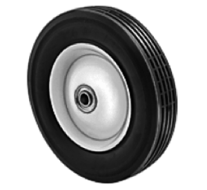
In order for the Pathfinder to complete the course it will need to be equipped with new wheels. These wheels will have to be strong enough to support the load of the entire pathfinder and rugged enough to withstand the environment that the course will provide. The picture above is of a wheel sold by McMaster-Carr that may be used on the Pathfinder. The wheel is 6 inches in diameter and 1.5 inches wide. The axel has a diameter of 0.5 inches. The wheel hub is made of smooth steel and the actual wheel is made of solid rubber with hollow treads. The capacity of each wheel is 55 lbs. The wheel hub has ball bearings pressed into it to ensure smooth operation. Having a 6 inch diameter will allow the Pathfinder to get up stairs easier. Having a steel wheel hub may be too heavy therefore an aluminum wheel hub may be used instead.  A wheel mounting hub will be designed in the future. This hub will properly connect the DC motor to the wheel. A link to the wheel specs can be found in the source material section.

Electrical, Wiring, AC Unit


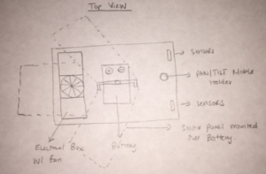
Figure 12: Electrical box and top view of the chassis

It is necessary that all electronics be protected during the mission. An electrical box will be used to house all of the electronics such as the micro-controller and motor driver shields. The electrical box may be made out of metal or plastic and will be mounted in the best place possible to ensure even weight distribution. A cooling fan might be used in case the heat produced by the electronics gets too high. This fan will be built into the electrical box along with vents to ensure proper air flow. Future tests will need to be run with the electronics engineer to see how hot the electronics get. All wiring will be neatly mounted and covered for protection. The battery is the heaviest part of the electric system and will need to be mounted in the center of the base platform in order to maintain even weight distribution. The picture above shows a general idea of where the electronics will be mounted on the base platform relative to everything else.

Solar Panel Interconnection

The design of the actual solar panel support is not in our scope of work but it is necessary for us to know how it will look in order for us to figure out how it will be attached to the chassis. It is crucial that the solar panels have good weight distribution and that they are mounted on the base platform in the correct location. Working with the Solar Panel Group in the future will be necessary in order to figure out what the best location is.

Source Material

Spirit Rover:

https://en.wikipedia.org/wiki/Spirit_(rover)

Wheels:

http://www.mcmaster.com/#2331t11/=149w7jd

General Information on spring 2016 Pathfinder:

http://arxterra.com/spring-2016-pathfinder-preliminary-design-documentation/

Design and Unique Task Description

The following tests and experiments shall be conducted.

Solidworks simulations will need to be performed in order to figure out if the new lighter chassis is strong enough and to see if the center of mass is in the appropriate location. These tests include load and shear analysis (stress test) and various animations

Rolling tests will need to be performed on the new wheel to make sure they do not wobble and have a smooth rotation.

Pan/tilt platform may be animated to show proper mobility.

Weight distribution test with solar panel connected.

Fall 2016 Velociraptor (Th): Preliminary Design Document

Project Manager – Paul Ahumada

Electronics and Control Engineer – Kevin Armentrout

Manufacturer and Design Engineer – Victoria Osaji

Systems Engineer – Robert Licari

Table of Contents

Program Objectives/Mission Profile

By Paul Ahumada

3rd Generation Velociraptor is a robot developed by the CSULB 2016 Fall Semester class that will expand on previous semester’s designs. The Velociraptor is to be a toy resembling Theropoda dinosaurs. Velociraptor shall compete in a Jurassic/Modern Game: Save The Human with other toys on the last day of class, December 15, 2016. The game will involve Velociraptor chasing another robot through various terrain by tele-robotic communication on the Arxterra Control Panel. The arena the Velociraptor must traverse is developed by the Game Committee and customer. The mission will display the robotic applications of the 3DoT Board developed by Arxterra and Velociraptor’s movement capabilities. – PM Paul Ahumada

Requirements and Verification

Program/Project

By Paul Ahumada

Level 1 Program Requirements

The Level 1 Program Requirements may resemble this:

  1. The 3rd Generation Velociraptor shall participate in the Game: Save The Human proposed by the game committee
  2. 3rd Generation Velociraptor budget shall not cost more than $450.00. This estimate was based upon 2nd and 1st Generation Bipeds [7]  [15]
  3. The Velociraptor shall demonstrate its capabilities on this December 15, 2016 according to CSULB Calendar 2016-2017 [14]

Level 1 Project Requirements

The Level 1 Project Requirements may resemble this

Level 1 Requirements

  1. The Velociraptor shall resemble a T-Rex of the Theropoda Dinosaur class [13]
  2. The Velociraptor shall navigate through the game terrain provided by the game committee. Velociraptor shall:
    1. Navigate on incline/declines no greater than 6.5 degrees
    2. Shall navigate on uneven surface heights no larger than .5 cm
    3. Shall utilize a foot design capable of traction on all surfaces
    4. Battery shall provide sufficient power to robot for duration of the game
  3. The Velociraptor shall statically walk [16]
  4. The Velociraptor shall dynamically walk [16]
  5. The Velociraptor shall use Bluetooth to communicate with Arxterra Control Panel  [17]
  6. The Velociraptor shall use a 3DoT board and implement I2C [17]
  7. The Velociraptor shall use a Portable Power Source

System/Subsystem

Level 2 System Requirements

By Paul Ahumada

  1. Shall implement a control system [PID or State Space] which shifts CoG on axis of legs maintain stability. The CoG shall be changed by two servos. There is one servo to control the head and one servo to control the tail. The acceleration and velocity of the CoG of the head and tail shall not exceed [data to be calculated] in order to avoid having momentum tip over the robot.  [Level 1-1]
  2. Shall implement control system [PID or State Space] which shifts CoG on axis of head, body and tail to maintain stability. The CoG shall be shifted by a servo controlling the platform of the body. The acceleration and velocity of the CoG of the body shall not exceed [data to be calculated] in order to avoid momentum causing robot to fall down. [Level 1-1]
  3. Shall have two legs supporting mass of robot. [Level 1-1]
  4. Shall use leg design that operates with cyclical movement that shall be controlled by a DC motor. [Level 1-1]
  5. Shall implement a control system which shifts the CoG over the planted leg while statically walking. The shifted CoG mass shall be within [to be calculated value] mm center of foot. The distance shall not consider vertical distance, Z. The distance from CoG and center of foot shall be calculated by margin of stability [to be calculated]. [Level 1-3]
  6. Shall implement a control system which tracks X, Y, and Z angles to the [to be found] precision. [Level 1-4]
  7. Shall implement a control system which tracks acceleration in the X, Y, and Z planes to the [to be found] precision. [Level 1-4]
  8. Shall track head and tail position to shift CoG by collecting data of servo angles to the [to be found] precision [Level 1-4]
  9. Shall utilize Bluetooth LE interface to provide Velociraptor commands from Arxterra Control Panel [Level 1-5]
  10. Shall connect head and tail servos via 3DoT Board servo interface. [Level 1-6]
  11. Shall implement an IMU [to be determined what kind] that communicates via I2C at a frequency rate [to be found] Hz. IMU data that collected shall be implemented into control systems. [Level 1-6]
  12. Shall use a CR123A 650mA rechargeable Li-ion battery from 3DoT Board [Level 1-6]
  13. Shall implement a motor controller [to be determined what kind] on the motor shield that communicates via I2C at a frequency rate [to be found] Hz. [Level 1-6]
  14. May use rechargeable batteries to power the Robot. [Level 1-7]
  15. The robot shall be able to continuously operate in game arena for minimum one hour. [Level 1-2]
  16. IMU shall send data as inputs to control systems for dynamic stability when encountering uneven surfaces and incline/declines [Level 1-2.1]
  17. Model of foot [to be decided] design shall [calculated] surface area to provide stability and not impede movements
  18. Traction of foot [to be determined] shall provide enough friction on all surfaces [study to be shown] of game terrain to prevent raptor falling over.  [Level 1-2]
  19. Shall change direction, left or right, by [to be determined arc] while walking. [Level 1-1]
  20. Shall be able to change direction for range 0-360 degrees, left or right, while not walking. [Level 1-1]
  21. Arduino Microcontroller Leonardo shall implement control algorithms [to be made] to be used in stability and user control of robot. [Level 1-7]

Level 2 Subsystem Requirements

Electronics Subsystem Requirements

By Kevin Armentrout

  1. Shall use batteries with a series terminal voltage of 3.7V. [Level 2-12] [4]
  2. Shall use leg motors with a gear ratio to produce a stall torque rating of at least 223 mN-m [Level 2-3] [Appendix]
  3. Shall use a leg design with a primary lever arm length of at a maximum of 7cm [Level 2-3] [Appendix]
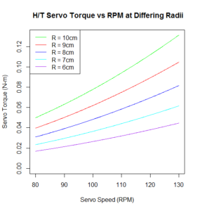
  4. Shall use head and tail servos which produce a minimum of 50 mN-m of torque at 80 RPM and 125 mN-m of torque at 130 RPM. [Level 2-1] [Head and Tail Torque Graphs]
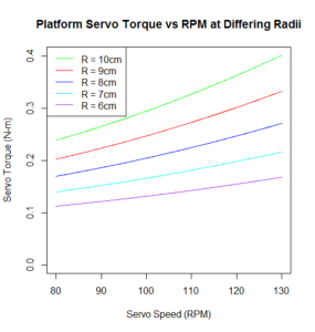
  5. Shall use a platform positioning servo that operates with a max speed of 80 RPM and a minimum torque rating of 238 mN-m. [Level 2-18] [Platform Graphs]
  6. Shall use a turning servo with a minimum torque rating of 139 mN-m. [Level 2-19] [Appendix]

Design Innovation

From our Creativity Presentation, we were able to generate ideas on how to talk challenges the 3rd Generation Velociraptor encounters. Major problems we must tackle for Fall 2016 is the ability to turn, CoG shifting along axis of head and tail, and changing the legs to cyclical movements. We have come across different solutions for each of these. For turning, we are thinking of using a servo to help the legs orientate a change in direction. Stabilizing an inverted pendulum will be the basis of our stabilization for the axis along the head and tail. Finally, the legs we are considering using are the UCI linkages because of their unique step pattern compared to Theo Jensen.

Creativity Exercise

Systems/Subsystem Design

Product Breakdown Structure

TBA

Electronic System Design

System Block Diagram

 electronic-interface-min

The electronic interface provides an idea of how the customer provided 3DoT board will move our robot. We used the 3DoT Block Diagram to get started. We will need a motor shield to connect to external devices that cannot fit onto the 3DoT board. Luckily, there is an I2C interface from the 3DoT board that allows us to add more devices. Because we need an I2C interface, we need an I2C chip that can connect to the amount of devices we needed. The I2C chip is explained in the Electronics research under design descriptions. The reason we do not have our DC motors directly connected to the 3DoT board is because it will always blow the polyfuse as determined by the mass of the robot. Further research will go into whether the 3DoT Dual Motor drive is the best fit in our motor shield. The electronics research goes into detail of the torque required to move our mass and the rpm needed.

Interface Definitions

TBA

Mechanical Design

TBA

Design and Unique Task Descriptions

Project Manager Research

As part of the game arena, friction coefficients of the surfaces must be found so our robot can maintain traction throughout the game. The table provided below shows that rubber has a higher static coefficient on cardboard than linoleum. This information helps if we would like to have rubber soles on our robot. Information that would be valuable that could not be found would be using plastic and also a study for friction coefficients on carpet. This information can be found from experimentation of by having a pulley design with one end having a mass dangling in the air and another end having our plastic or rubber mass. As we add more weight to the dangling mass, eventually the plastic or rubber mass on a surface will move.

Case Study Friction Coefficients Static Frictional Coefficient
Rubber on Cardboard .5-.8 Source Cardboard
Rubber on Linoleum .3-.5 Source Linoleum

Electronics Research

By Kevin Armentrout

Leg Motors

Level II System requirements dictated that motors would be used as the locomotive method for the Raptor robot. This is challenging for a number of reasons. First, motor position cannot be accurately controlled to specify angles of motion. Even if motor shaft position was monitored by means of a rotary encoder or other shaft measurement device, starting position would be a challenge. Secondly, motors tend to occupy a larger space and weigh more than servos. [1]

Analysis was performed in R to measure the maximum and operational torque values of various lever-arms, using the weight from the previous semester’s raptor as a basis for analysis. Full analysis code is in the appendix below. This analysis was performed using lever arms from 6 to 10 cm and calculating the maximum operational torque due to gravity and centripetal force. 10cm was approximately the length of the raptor’s head, leg and tail from last semester. Our design would be a modification from the previous semester so it was important to consider other level arm distances that were not used from last semester. This importance was especially emphasized by the fact that the legs will need to be completely redesigned to allow for continuous motion. This brought upon the condition that the primary lever arm of the motors and servos may need to change to conform to motor torque requirements, thus the range from 6 to allow for further lever arm considerations.

Once maximum torque values were calculated, torque over the leg motion cycle was calculated by applying a sin to the position. Cursory analysis of the primary lever arm, which would be exerting the highest magnitude of torque on the motor, showed that the lever arm typically rotated between 210 and 330 degrees [2]. This corresponded to a value, which I identify as a realistic maximum, or sin(60) of the calculated maximum. Logical analysis of leg locomotion confirms this. Using the Y-Axis of your leg as a reference, it typically will not exceed 60 degrees on a single stepping motion. The realistic torque values for the legs at various lever-arm lengths is listed in the appendix below.

leg-torque-min

Head and Tail Servos

The level II requirement that dictated the need to move the head and the tail stemmed from the need to shift the CoG to the planted foot, or maintain in stationary during dynamic movement. To evaluate how the CoG will shift, an analysis on moments of inertia needed to be performed over the full motion of the tail. Disassembly of the previous semester’s raptor to weigh the individual segments was impractical, so an analysis of material density, and weight of the components used on the head and tail segments was done in its place.

Density of ABS plastic, as well as length and width of the tail was taken into account, as well as the dimensions of the battery holder. The batteries used were AAs, and dimensions and weight of the AA batteries were taken into tail and head mass calculations. The torque was based on centripetal speed of the servos. Analysis of 5V servos showed that the majority of servos were in the 80-130 RPM range, which was used for our analysis of torque due to centripetal force.

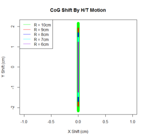
An additional factor for consideration, similar to the legs, was varying the head and tail radius, and its effect on the CoG and centripetal torque. Servos must be selected with torque rating that is greater than the curve shown below for the specified radius length.

cog-change-min

servo-torque-h_t-min

Platform Servo

The platform servos will be used to move the entire control surface of the body in order to account for changes on the X-Z plane. In order to facilitate movement of the surface along this plane, we will need to account for the mass of the head and tail, as the Body components near the CoM will produce negligible torque due to the lever arm being of a small radius. This simplified the torque calculations to only concern the centripetal force of the motion along the Y axis, and the torque related to gravity. Below is the calculated chart with different servo speeds and head/tail radii. The selection of the Platform servo must exceed these values.

servo-torque-vs-servo-speed-min

Turning Servo

Unlike the other electric components, the turning servo must be able to turn the entire platform left and right to control the robot’s direction. This requires the torque that is applied to the servo to not only be the entire mass of the robot, but also the additional force due to the frictional coefficients of the surfaces of the robot will walk on. The calculated number is the torque on the servo solely due to the mass of the robot. This number, still, is quite substantial, and other solutions may be needed to be explored to allow the robot the ability to turn in a precise manner.

Batteries

Batteries are to be considered for the following purposes. Primarily, their current capacity, as it will provide the necessary resource to power the robot’s electronics and actuators, and secondly, it’s form factor and weight as a method of balance for the robot. Last semester, and the semester previous did a clever design with the batteries, placing them as counter weights on the head and tail. This evenly distributed the CoG along the X and Y axis, and also allowed the CoG to shift as the tail moved.  For this purpose, the AA form factor for batteries was considered as counter weights and primary power, and the slim form factor is considered as platform supplementary power.

Current draw was calculated by use of manufacturer ratings for representative components that fit the requirements for the motors and sensors, as well as the components of the 3DoT board. However, servo current load is not a required manufacturer listed quantity, and as such, is simply not listed on any of the servos we examined. Additionally, all servos listed on Sparkfun, Adafruit, Digikey, and Mouser have a minimum 5V rating. This would change the current-hours equivalent to a Watt-hour equivalent for consistency, as all other components will be powered via the 3.3V bus. For these points the servo calculations will be ignored for this initial power consumption analysis as they are not representative of actual values, and would be a best guess approximation.

The calculations took into account average motor load and peak sensor load to determine the following. Once again, these numbers are representative, and are not the actual final values that will be used for a full power analysis.

I2C

I2C functions in a daisy chain manner similar to USB, but has an address structure that is different. I2C can support up to 127 different addresses, but these addresses are unique and programmed at the hardware level [3]. Thus it is important that these addresses do not overlap in order to have proper sensor and control function. The 3DoT board is equipped with 2 Motor headers, 2 servo headers, and an I2C header, leaving at minimum 2 Servos that would need I2C control, and the IMU which would need I2C communication [4].

Motor Controller

A derived requirement from the number of servos and motors need for Robot operation is the need for an external motor controller shield. If the motors are to be placed on the shield, bi-directional motion would be necessary. This can be accomplished by means of an H-Bridge [5]. For the servos that would be attached, a PWM I2C controller would need to be utilized to ensure proper control over the devices. An ideal solution for rapid prototyping is a board that has both PWM functionality and H-Bridges for motor and servo control.

Inertial Mass Unit (IMU)

The need for an IMU comes from the requirement for dynamic stability of the Robot. In order to maintain the Robot dynamically stable, an accurate accountancy of both angular position on a three dimensional axis, and inertial shift detection by means of an accelerometer [6].  Due to the 3DoT board not having external pin headers except for those listed in the I2C descriptions, the interface for communicating with the IMU must be I2C.

Appendix

Peak Torques (N-m)
Radius 10 cm 9 cm 8 cm 7 cm 6 cm
Component Platform 0.238 0.203 0.170 0.140 0.113
Legs 0.279 0.251 0.223 0.192 0.167
Head/Tail 0.050 0.040 0.031 0.023 0.017
Turning 0.139 0.123 0.108 0.093 0.079


Representative Components Which Met Torque Criteria
Servo/ Motor Torque

(N-M)

Weight

(g)

Cost

($)

NL Current

(A)

FL Current

(A)

RPM Notes
Motors
ROB-12399 0.322 119 24.95 0.095 0.5 101 (@12V) [A6]
Tamiya 72005 0.235 140 13.95 0.15 2.7 51.3 [A7]
Tamiya 70168 – Double 0.223 120 9.25 0.15 2.1 38 [A1]
Servos
FS5103R 0.294 40 11.95 NL NL 80 (@5v) [A8]
EMAX ES08A 0.148 8.5 9.9 NL NL 83.3 (@5v) [A9]
Seeed 108090001 0.197 12.25 21.9 NL NL 83.3 (@5v) [A10]
Seeed 108090002 0.245 19.96 24.9 NL NL 100 (@5v) [A11]


Component Average Current Source
Leg Motors 1.583 A [A1]
Leonardo (3DoT) 0.56 A [A2-A3]
IMU 0.00686 A [A4]
Motor Shield 0.01 A [A5]
Total 2.16 A


R Source Code for Calculations

# Determined by the Servo


stepSize = (pi/180)*(360/3000)

thetaHead = seq(-pi/2,pi/2,stepSize)

thetaTail = -thetaHead

thetaLeg = seq(0,2*pi,stepSize)

# In RPM

MaxSpeed = seq(80,130,.1)


# Max Incline on Y Axis


MaxY = (6.5*pi/180)


# Centripital Acceleration

# http://www.engineeringtoolbox.com/centripetal-acceleration-d_1285.html


A = (2*pi*MaxSpeed/60)^2 * Radius/100


# AA weight is 23g

# AA dimensions are in cm, which is used to determine ABS plastic

# Battery holder mass

# http://data.energizer.com/PDFs/E91.pdf


innerLength = 5.050

innerWidth = 1.450 *2

innerHeight = 1.450


outerLength = innerLength + .5

outerWidth = innerWidth + .5

outerHeight = innerHeight + .5


HolderVolume = (outerLength * outerWidth * outerHeight) – (innerLength * innerWidth * innerHeight)


AA = 23

# ABS plastic weight is .97g/cc

# http://www.stelray.com/reference-tables.html


ABSDensity = .97


# Calulate tail and head weight

# Thickness of 1cm for consistant calculations


tailMass = 2*(AA) + (Radius*(1^2) + (HolderVolume)) *ABSDensity

headMass = tailMass


# Previous Semester’s Robot Mass in grams

# https://www.arxterra.com/spring-2016-velociraptor-project-summary/#Size_Weight


Mass = 657

BodyMass = Mass – tailMass – headMass


HeadPositionX = Radius*cos(thetaHead)

HeadPositionY = Radius*sin(thetaHead)


TailPositionX = -Radius*cos(thetaTail)

TailPositionY = -Radius*sin(thetaTail)


# For moments of mass


TailMassX = TailPositionX * tailMass

TailMassY = TailPositionY * tailMass


HeadMassX = HeadPositionX * headMass

HeadMassY = HeadPositionY * headMass


X_Moment = (TailMassX + HeadMassX) / (tailMass + headMass + BodyMass)

Y_Moment = (TailMassY + HeadMassY) / (tailMass + headMass + BodyMass)


g = 9.8


LeverArm = max(Y_Moment)

# Torque due to gravity (Y Axis)


MaxTorqueHeadY = (headMass/1000) * g * Radius/100

MaxTorqueTailY = (tailMass/1000) * g * Radius/100


# Realistic torque due to gravity


RealisticTorqueHeadY = MaxTorqueHeadY * sin(MaxY)

RealisticTorqueTailY = MaxTorqueTailY * sin(MaxY)


# Torque due to Acceleration (X Axis)


MaxTorqueHeadX = (headMass/1000) * A * Radius/100

MaxTorqueTailX = (tailMass/1000) * A * Radius/100


# Platform Maximum Torque (Y Axis)


MaxTorquePlatform = MaxTorqueHeadY + MaxTorqueTailY + ((headMass/1000) * A * Radius/100) + ((tailMass/1000) * A * Radius/100)


# Frictionless Turning Torque


MaxTurningTorque = ((Mass/1000) * g) * LeverArm/100


# Frictionless Leg Moving Torque


MaxLegTorque = (Mass/2)/1000 * g * LegRadius/100

LegTorque = abs(MaxLegTorque * sin(thetaLeg))

RealMaxLegTorque = abs(MaxLegTorque * sin(60/180 * pi))


Manufacturing Research

Materials Trade-Off Study:

The previous semester, spring 2016, did a very detailed material trade-off study that we liked based on Aluminum and PLA Filament (3D printing material). We found this very useful because we have ideas that we can now build off of. Although, our design may differ in some places and our requirements have changed a bit these are still information we can use because the basics requirements are covered such as walking statically and dynamically and being able to walk up and down uneven surfaces. What I really liked most is that they used the two different material depending on their needs. They used the aluminum for their bottom piece because they wanted to maximize the weight on the head and tail. Then they used the PLA filament for the foot that way the robot could walk statically and dynamically without slipping on different surfaces.

Unique Design:

Victoria Osaji

  1. Create a 3D model of the Velociraptor using Solidworks. Send out to be 3D printed. (4 weeks)
  2. Simulate the model and perform all testing in Solidworks. (2 weeks)
  3. PCB Design on EagleCAD. (2weeks)

Sources

Project Manager:

  1. Spring 2016 Velociraptor: Preliminary Design Document
  2. Spring 2016 Velociraptor: Project Summary
  3. Spring 2016 Verification Test
  4. Spring 2016 Velociraptor Final Project Video
  5. Friction Coefficient Cardboard
  6. Game: Save The Human
  7. Spring 2016 Cost Report
  8. Spring 2016 Work Breakdown Structure
  9. Spring 2016 Completed Schedule Breakdown
  10. Spring 2016 Burn Down Chart
  11. Spring 2016 A-TechTop Research Project
  12. CSULB Health and Safety Documents
  13. Theropoda Picture
  14. CSULB 2016-2017 Academic Calendar
  15. Fall 2015 MicroBiped Final Cost
  16. Definition Static and Dynamic Walking
  17. 3DoT Board
  18. Game: Save The Human
  19. Source Linoleum

Electronic and Control:

  1. http://handyboard.com/hb/faq/hardware-faqs/dc-vs-servo/
  2. http://sites.uci.edu/markplecnik/projects/humanoid-gait/
  3. https://learn.sparkfun.com/tutorials/i2c
  4. https://www.arxterra.com/3dot/
  5. http://www.modularcircuits.com/blog/articles/h-bridge-secrets/h-bridges-the-basics/
  6. https://www.sparkfun.com/pages/accel_gyro_guide
  7. http://daf.csulb.edu/offices/ppfm/ehs/programs/esp/electrical_safety_program.pdf (Working Near Exposed Live Parts section)
  8. https://www.ada.gov/regs2010/2010ADAStandards/2010ADAstandards.htm (Ramps Section)
  9. [A1] https://www.pololu.com/product/114
  10. [A2] http://www.atmel.com/Images/Atmel-7766-8-bit-AVR-ATmega16U4-32U4_Datasheet.pdf (Section 29)
  11. [A3] https://www.arxterra.com/3dot/
  12. [A4] https://learn.adafruit.com/adafruit-10-dof-imu-breakout-lsm303-l3gd20-bmp180/design-files (Each component listed individually)
  13. [A5] https://learn.adafruit.com/adafruit-motor-shield-v2-for-arduino/resources
  14. [A6] https://www.sparkfun.com/products/12399
  15. [A7] https://www.pololu.com/product/74/pictures
  16. [A8] https://www.adafruit.com/product/154
  17. [A9] https://www.seeedstudio.com/EMAX-9g-ES08A-High-Sensitive-Mini-Servo-p-760.html?gclid=CPzajsTKqb8CFYhafgodCKsA7A
  18. [A10] http://www.digikey.com/product-detail/en/seeed-technology-co-ltd/108090002/1597-1199-ND/5488079
  19. [A11] http://www.digikey.com/product-detail/en/seeed-technology-co-ltd/108090001/1597-1198-ND/5488078

Manufacturer:

  1. http://sites.uci.edu/markplecnik/projects/leg_mechanisms/leg_designs/
  2. https://www.arxterra.com/spring-2016-velociraptor-material-trade-off-study-update/
  3. https://www.arxterra.com/spring-2016-velociraptor-hardware-simulation/
  4. https://www.arxterra.com/spring-2016-velociraptor-spring-experiment/

Fall 2016 Game: Save The Human


Gaming Committee Team Members:

Velociraptor (Th) – Paul Ahumada

Velociraptor (W) – Lam Nguyen

Biped – Gifty Sackey

Goliath – Kristen Oduca

Table of Contents

Overview:

Biped has accidentally lost his way in the forest. Unbeknownst to Biped, Velociraptors lurk in the shadows. Biped must flee to the safe haven before the raptors get him. Better pick up a weapon and protect yourself! All robots shall navigate through terrain of the arena.

Rules:

  • Robots start at designated starting zones
  • If Biped makes it to the safe-haven zone, Biped wins
  • If Velociraptors make contact (touch) with Biped or Biped does not reach the safe-haven zone, Velociraptors win
  • Goliath shall only follow Biped
  • Biped can use a sensor to sense a weapon on a space that is 4inx4in. Biped will actuate (something obvious to the Velociraptor teams) that they currently possess a weapon. They remain invincible for 5 minutes. If a Velociraptor touches the Biped while it is invincible, they are given a yellow card. If they do this a second time, they are given a red card and will be removed from game by IA or Professor
  • Time Limit of 60 minutes
  • If a robot falls down during the game due to terrain, they are considered out and will be removed from game by IA or Professor
  • If Goliath accidentally bumps into any of the robots and knocks them down, that robot is removed from game by IA or Professor

View and control:

  • Biped controller shall see via Arxterra Android or iPhone mounted on Goliath and will operate in RC mode
  • Velociraptor teams shall see via cameras in fixed positions in game course and operate tele-robotically from the Arxterra control panel

Terrain:

  • Terrain shall be supplied by the participants
  • Arena size shall be front a 12ftx5ft
  • Terrain shall consist of cardboard
  • Terrain shall consist of no more than 30% of the arena area
  • Surfaces of arena shall consist of classroom floor (linoleum) and cardboard
  • Terrain shall be assembled by Customer and IA without the knowledge of participants
  • Terrain objects shall consist of hills and uneven surfaces made of cardboard
    • Hills shall be a maximum of 1ftx1ft in area
      • Terrain incline/declines shall be no larger than 6.5 degrees
      • Uneven surfaces shall not be larger than .5cm in height when stepping on
    • Uneven surfaces shall be strips of cutout cardboard with an area no larger 1inx1in
      • Uneven surfaces shall not be larger than .5cm in height


Fall 2016 Velociraptor (W): Preliminary Design Documentation

By: Lam Nguyen (Project Manager)

Hal Vongsahom (System Engineer)

Taylor Farr (Controls Engineer)

Aaron Choi (Manufacture Engineer)

Program Objective

Lam Nguyen (Project Manager)

The Fall 2016 Velociraptor is inspired by both the biped Titrus-III robot and the Theo Jansen biped robot. The Titrus-III was developed by the Tokyo Institute of Technology and the Theo Jansen biped robot was designed by the Gakken company. The objective for this year’s project is to avoid utilizing servos by implementing alternative motors to meet the customer’s demand. The most compatiable design for using alternative motors is the Theo Jansen biped robot known to model human giat motion that utlize continuous rotion with linkages.

Mission Profile

Lam Nguyen (Project Manager) 

The Fall 2016 Velociraptor had the wonderful opportunity to be included in this years Game Arena called “Save the Humans”. Representing the dromaeosauridae theropod dinosaur from the Cretaceous period the fall the the Velociraptor will navigate through the game arena terrain and hunt down the Biped robot before reaching the safe-haven zone in a time duration of 30 minutes.

The Fall 2016 Velociraptor will demonstrate its navigation cabablities by operating telerobotically from the Arxterra control panel. With a fixed view of the game arena the Velociraptor will navigate through both flat surfaces and uneven surfaces such as linoleum and cardboard.

Requirements

Program Level 1 Requirements

Lam Nguyen (Project Manager)

  1. According to the CSULB Fall 2016 Academic Calender, the Velociraptor biped robot shall be tested by Wednesday, December 14, 2016, the last day of EE400D [1].
  2.  The Fall 2016 Velociraptor biped robot budget shall be a limit of $400.00 [2].
  3.  The Fall 2016 Velociraptor biped robot shall participate in the game “Save the Humans” defined by the game committee. [3]

Project Level 1 Requirements

Lam Nguyen (Project Manager)

  1. The Velociraptor biped robot shall resemble dromaeosauridae theropod dinosaur from the Cretaceous period. [4]
  2. The Velociraptor shall be able to statically walk on the terrains of the game arena.
  3. The Velociraptor shall be able to dynamically walk on the terrains of the game arena.
  4. The Velociraptor shall use Bluetooth communication with the Arxterra Android or Iphone application.
  5. The Velociraptor shall use a 3DoT board with a custom I2C shield.
  6. The Velociraptor shall navigate through the game arena’s terrain.
  7. The Velociraptor shall use a portable power source for the duration of the game “Save the Human”.

References

[1] Time, B. C. (n.d.). Final Exam Fall 2016 Schedule Charts. Retrieved September 21, 2016, from http://web.csulb.edu/depts/enrollment/registration/final_exam/fall_chart.html

[2] Khoivu0814. (2016). Retrieved September 21, 2016, from https://www.arxterra.com/spring-2016-velociraptor-preliminary-project-plan/

[3] Index of /~hill/ee400d. (n.d.). Retrieved September 21, 2016, from http://web.csulb.edu/~hill/ee400d/F’16%20Project%20Objectives%20and%20Mission%20Profile.pdf

[4] Dromaeosauridae. (n.d.). Retrieved September 21, 2016, from https://en.wikipedia.org/wiki/Dromaeosauridae

System/Subsystem Requirements

Project Level 2 Requirements – System Requirements

Lam Nguyen (Project Manager)

Hal Vongsahom (System Engineer)

Taylor Farr (Controls Engineer)

Aaron Choi (Manufacture Engineer)

  1. The Velociraptor shall walk on two feet and use both head and tail to control the robot’s center of gravity.
  2. The Velociraptor shall implement the head and tail to shift it’s center of gravity on one foot in order to statically walk in the game arena’s terrain.
  3. The Velociraptor shall use an accelerometer and a gyroscope to detect its reference to x, y, z space to adjust it’s center of gravity to dynamically walk in the game arena’s terrain.
  4. The Velociraptor shall use an HC-06 Bluetooth to communicated with the Arxterra Application to control the robot’s movement.
  5. The 3DoT board shall receive commands from the HC-06 Bluetooth and decode the command data, and transmit the command data to the I2C to control the actuators.
  6. The Velociraptor shall provide a lithium polymer battery to provide power for the duration of 30minutes from the game objective.
  7. The Velociraptor shall be able to travel up an incline/decline slope no larger than 6.5 degrees.
  8. In order to navigate around the game arena’s terrain the Velociraptor shall travel on cardbaord and class room floor, uneven surfaces of the terrain shall be no larger than 0.5 cm.

Subsystem Level 2 Requirement

Taylor Farr (Elecontrics Engineer)

  1. In order for the velociraptor to be able to operate properly, an input and output system must be designed. For our inputs, we will be using a digital accelerometer to measure acceleration as well as a gyroscope to determine the position from a neutral point at any given time. [1] & [4]
  2. The accelerometer shall be digital in order to reduce coding(Help from Hal). Trade-off studies shall be conducted in order to find an appropriate accelerometer that is compatible with Arduino. [1]
  3. For actuators, motors shall be use to move the Velociraptor forward and performing actions in order to keep it stable. [2]
  4. Servos shall be implemented in the head and tail to move the head and tail to shift the center of mass 30 degrees in either direction. In order to correlate the sensors and actuators, a microprocessor is required to interpret the data at input pins and then provide the appropriate signals to the output pins in order to activate the motors and servos. [2]
  5. The motors for the legs shall provide enough torque to support the 900 grams. Operating speed shall be determined by how fast the velociraptor needs to move in order to control its dynamic walk. The torque necessary to move the robot and support the 900 grams must be taken into consideration. This calls for a trade-off study of motors and servos in order to pick the appropriate ones. [3]
  6. Based on the speed and torque required, trade off studies shall be conducted to find an appropriate power supply that supplies enough current at the appropriate voltage.
  7. Fritzing diagrams shall be utilized in order to map out circuits connected to Arduino that provide appropriate and accurate data. Once this has been established, we will model the electronics in LT Spice, send the circuits to Eagle, and then design the PCB.

Aaron Choi (Manufacturer Engineer)

  1.  In order to meet the customer’s demand in alternative motors the Velociraptor shall use the Theo Jansen Biped robot’s linkages for continuous movement. [5]
  2.  In order for the Velociraptor to operate the mass shall not surpass 1000 grams.

References

[1] MAV-blog. (n.d.). Retrieved September 21, 2016, from http://tom.pycke.be/mav/69/accelerometer-to-attitude

[2] @. (2014). How a Robot Can Keep Its Balance and Stand up Even if it Gets Kicked – Case Study – Smashing Robotics. Retrieved September 21, 2016, from http://www.smashingrobotics.com/how-a-robot-can-keep-its-balance-and-stand-up-even-if-it-get-kicked-case-study/

[3] http://www.robotshop.com/en/gear-motors.html

[4] MAV-blog. (n.d.). Retrieved September 21, 2016, from http://tom.pycke.be/mav/70/gyroscope-to-roll-pitch-and-yaw

[5] @. (n.d.). Theo Jansen-style Biped Robot kit by Gakken. Retrieved September 21, 2016, from https://www.adafruit.com/product/1841

Design Innovation

The team worked off of the creativity presentation, with ideas bouncing back and forth we considered additional problems and applied our research to find a solution. One of the main problems we have considered are the motors which provides a continous rotion for our Velociraptor. Since the customer demands motors instead of servos, that effects the design of the legs as well. For a model to follow we bought a Theo Jansen Biped Robot for further study of the linkages for the legs. We will create a design for the legs and chassis that with less amount of material as possible for prototyping.

Creativity Presentation

Creativity Presentation PowerPoint

System/Subsystem Design

Product Breakdown Structure

Hal Vongsahom (System Engineer)


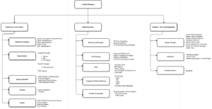
Product Breakdown Structure

Figure 1

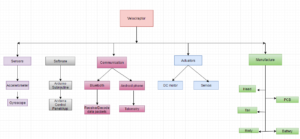
The image display on Figure 1. the product breakdown structure.  This is a high overview of the structure flowing from the top down to the structure and component of the velociraptor.

Power

The velociraptor shall be power by a portable supply source. The battery will power the systems 3Dot board, I2C, DC motors, Servos, and the Accelerometer/Gyroscope. This can be thought of as the food and energy necessary for the velociraptor to move.

Software

The software required by the customer is the Arxterra app. The Arxterra acts as a friendly user interface that will help control the movement of the velociraptor. The codes will be written in C++ in Arduino. All of the subroutine will be develop to properly control the movements of the velociraptor.

Communication

The main component to the velociraptor communicating properly is dependent on the Bluetooth. The Bluetooth will receive data packets that must be decoded. The Bluetooth will receive data from the Android phone.

Actuators

The actuators for our system are DC motor and Servos. The DC motor will control the legs to perform walking. The servos will govern the head and tail movement for the velociraptor. Another conceptual way to think of the actuators are it is the muscle of our systems.

Manufacture

This can be considered the bones, and the entire body of our system. The manufacture of the velociraptor head, tail, and body will be printed and constructed. The PCB will also be design and printed out to form the blood vessels of the velociraptor.

Reasoning

The customer requires our velociraptor navigate through the game arena with different surfaces and inclines/declines. Therefore, it is important for the design to incorporate as many DC motors or Servos to not restrict movement of the velociraptor.

Electronic System Design

System Block Diagram

Hal Vongsahom (System Engineer)

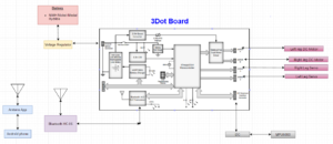
3dotboard

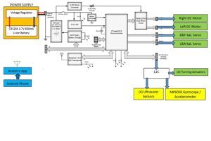
Figure 2

A system block diagram above shows the corresponding inputs, power, extended peripheral, outputs, and communication devices that will be use on this project. The image shows the input devices that will be sending data to the microcontroller will be the accelerometer and the wireless Bluetooth device. The communication that will contribute to controlling the velociraptor movement will be the Android phone and the Arxterra application. The portable battery device will power both the microcontroller, the I2C, and the outputs such as DC motors and Servos. This system diagram illustrates the important of the microcontroller acting as the brain for all other components to operate properly.

Interface Definition

Interface

Figure 3

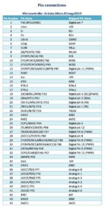
3Dot Board

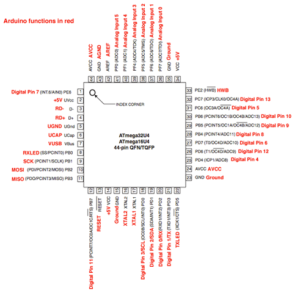
Figure 4

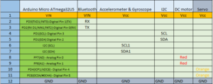
The above image in Figure 4 below lists all the pins in the Arduino microcontroller. It also gives a clear understanding of how much digital pins and analog pins are on the microcontroller. This can then lead to us designate each pin to control the devices needed for the velociraptor to operate successfully.

Assigned Pins for Input and Outputs

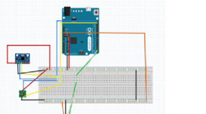
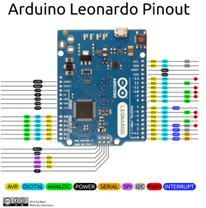
Figure 5

Pins for the velociraptor in the above image

System Resource Map

System

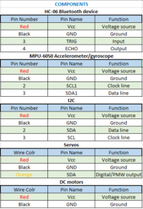
Figure 6

The table above list the system resource. A new requirement this semester from the customer is that we are required to have an I2C board. The 3Dot board is utilizing an Arduino Leonardo and the pins for SCL (Clock line) and SDA (Data line) are limited to one each. Therefore, we extend the SCL and SDA with the I2C board to connect the MPU-6050 accelerometer/gyroscope.

In addition, the primary design for our velociraptor will be using 2 DC motors and 2 servos. The DC motors only require a Vcc and Gnd, and the servos require PWM. If our design requires more DC motor or Servo we can add this on the 3Dot board pins or the I2C board. This will overall give us more flexibility.

Resources

[1] https://github.com/Bouni/Arduino-Pinout & https://www.arxterra.com/spring-2016-velociraptor-preliminary-design-document/

Mechanical System Design

Taylor Farr (Elecontrics Engineer), Hal Vongsahom (System Engineer), & Aaron Choi (Manufacturer Engineer)

Leg Design

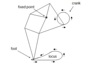
Previous generations of the Velociraptor utilized servos in the leg design. The controlled angle of rotation from the servos allowed the Velociraptor to walk statically. However, due to the customer’s demands, servos are not to be implemented within the leg design. Therefore, the Velociraptor shall utilize a DC motor. Since the DC motor use a continuous rotation, the Jansen’s Linkage shall be implemented with the leg design. The Jansen’s Linkage utilizes a joint to be driven by a continuous rotational motion.

Theo Jansen Linkage

Figure 3

In the Figure 3 above, the leg mechanism models a Jansen’s linkage. This system utilizes a fixed point and a rotating point to model the human walking gait.

Resources

[1] AMANDA GHASSAEI: HOME. (n.d.). Retrieved September 21, 2016, from http://www.amandaghassaei.com/files/thesis.pdf

[2] What’s The Difference Between DC, Servo & Stepper Motors? (2015). Retrieved September 21, 2016, from https://www.modmypi.com/blog/whats-the-difference-between-dc-servo-stepper-motors

Design and Unique Task Description


Taylor Farr (Elecontrics Engineer)

The previous semester was unsuccessful with dynamic walking due to their sensors. They used an analog accelerometer to measure walking up inclines, and the previous semester did not use a gyroscope. The problem with analog is the converted codes will have tons of lines of codes. Therefore, compile too much memory on the Arduino Leonardo. In addition, there sensors was not accurate because they did not use a gyroscope. Therefore, this semester we are using a gyroscope in our system. This can monitor the displacement of the body from the neutral balance state, and update in real time. Moreover, we will use a digital accelerometer and gyroscope so that the coding will be simpler thus speeding up the processing time.

Sensor Selection

We have selected the MPU0605 as the gyro/accelerometer. The reason we choose this particular device as a sensor is it has both the features of an accelerometer and gyroscope. It also has an analog to digital converter built in.

Motor Selection

Once the sensor has been selected, the next task is to select the appropriate DC motors for the legs. Some options are brushless, brushed, shunt, series, or stepper. From these options, we will conduct trade off studies. Based off these studies, we will select the appropriate motors and servos that satisfy the torque and speed needed based on weight requirements.

Power supply selection

Now that the motors have been determined, we will select the appropriate power supply based on the power consumption of the selected motors. Based on requirements, we will use lithium ion batteries.

Aaron Choi (Manufacturer Engineer)

  1. Project level 1 requirements describe the velocraiptor to statically and dynamically walk. To improve the walking motion, the feet of the Velocraiptor shall implement a toe joint. This toe joint enhances performance and stability of biped robots [1], specifically increasing walking speed [2] and reducing energy consumption compared to a flat foot [3]

Resources

[1] Kwon, SangJoo, and Jinhee Park. “Kinesiology-Based Robot Foot Design for Human-Like Walking.” International Journal of Advanced Robotic Systems 9 (2012).http://cdn.intechopen.com/pdfs-wm/41665.pdf

[2] Ouezdou, Fathi Ben, Samer Alfayad, and Bachar Almasri. “Comparison of several kinds of feet for humanoid robot.” 5th IEEE-RAS International Conference on Humanoid Robots, 2005.. IEEE, 2005. http://ieeexplore.ieee.org/document/1573556/?arnumber=1573556

[3] Sellaouti, Ramzi, et al. “Faster and smoother walking of humanoid HRP-2 with passive toe joints.” 2006 IEEE/RSJ International Conference on Intelligent Robots and Systems. IEEE, 2006. http://ieeexplore.ieee.org/document/4059197/?arnumber=4059197


Fall 2016 BiPed : The Preliminary Design Documentation

By:    Gifty Sackey (Project Manager)

          Brandon Perez(Mission, Systems and Test)

          Ryan Daly(Electronics and Control)

          Ijya Karki(Manufacturing)

Table of Contents

Mission Objective and Mission Profile

– Gifty Sackey (Project Manager)

The Robot Company has assigned our engineering team to design the 6th generation of the Biped robot, however, this model will utilize a non-servo based walking motion. The Biped should be able to statically walk with a final goal of being able to demonstrate dynamic walking. The Biped should be able to walk on various surfaces and walk on terrains that have an inclination of a maximum 6.5 degrees. In addition to that, the Biped need to walk around while avoiding obstacles with the help of ultrasonic sensors. The design change was initiated due to the fact that prior Biped models had gears wear out before its mission objectives were completed. In the initial stage of the product, the customer would like this Biped to be able to run on DC motors and be able to turn both left and right on. At the end of the build, the Biped will be asked to participate in a game where it needs to be to be able to outrun velociraptors and climb over different inclinations.

Suggestions for future Biped teams:

  • Get approval for all purchases – Due to time constraints, our team was in a rush to get parts in to begin implementation.  We focused our attention on completing our mission objective without considering our customers’ expectations.  It is important to complete the objective as well as pleasing the customer.
  • Replace servos with better quality – We had servo issues throughout the semester. We always had a spare servo in hand due to the unpredictability of servo failure.
  • Make RoFi lighter – The servos would spasm causing RoFi to fall.
  • Lower the center of mass – Due to RoFi being so top heavy, it was difficult implementing walking on an inclined surface.
  • Implement the ultrasonic sensor, accelerometer/gyroscope and cordless walking – Due to customer request, we focused a lot of our attention getting RoFi to walk the figure 8 obstacle course and neglected other features.
  • Get RoFi asap – We had to do a lot of documentation throughout the semester, we did not get to work on RoFi until about one month into the semester.
  • Project Manager – As Project Manager I had a lot of paperwork in the beginning of the semester. Work slowed down in the third month, so I dedicated a lot of my time getting RoFi to walk and assisted the engineers where I could.
  • Be cautious of free 3D printing – Verify that the quality of the 3D printing material is to your liking.
  • Understanding the customer – Realize that the customer has multiple projects and classes and will claim things were said or were not said that you may need to address.  Communicate and verify all concerns with the customer, student teacher and president.
  • Update Mission Objective – Our mission objective said that the incline was 8 and 6 degrees; we measured the incline and it varied from 14 to 7 degrees.  The room was also a burden to work in because the room was popular for labs and lectures.

https://www.arxterra.com/spring-2016-rofi-project-summary/#Program_Objectives_Mission_Profile

Comments – Gifty Sackey (Project Manager)

I find this section of the blog post to have been extremely helpful.  The above section which was provided by last semester’s project manager identified areas to focus on when building future BiPed because they might have overlooked it when they were building their own robots. This section is to help us learn from last semester’s mistakes and have a little bit of an easier time when building future Biped robots.

Review of Literature

Analysis of Past Level 1 Requirements

Requirement Evaluation Rubric

  1. Is the requirement, Quantitative, Verifiable, and Realizable?
  2. Is the requirement located at the correct level (1 –Program/Project)
  3. Is the requirement response to a higher level requirement or customer’s objective (Requirement Flow Down)? Is the linkage clearly defined?
  4. Does requirement provide link to source material?
  5. Does requirement move the design process forward?
  6. Are equations used to calculate a requirement provided and are answers correct?
  7. The requirements that are missing are the hardest to discover and will be factored into your evaluation.
  8. Is language in form of a requirement?
  9. Avoid multiple requirements within a paragraph (i.e breakup statements that contain multiple requirements)
Requirements from Spring 2016 Wednesday Requirement Evaluation Rubric Number
1 2 3 4 5 6 7 8 9
Modifications to RoFi shall not exceed $320 Y N N N N N Y Y Y
RoFi shall acknowledge and avoid objects within 3 feet Y Y Y N Y Y N Y Y
RoFi shall traverse carpet, linoleum tile, and metal surfaces N Y Y N Y Y Y Y Y
RoFi’s runtime shall be greater than 15 minutes Y Y Y N Y Y Y Y Y
RoFi shall cross over a threshold, at approximately a 45° angle and a height of 2 cm Y Y Y N Y Y Y Y Y
RoFi shall ascend an incline that is initially an 8° slope which then decreases to a 6° slope Y Y Y N Y Y Y Y Y
RoFi shall complete the figure 8 obstacle course through the Arxterra Application during finals week (Monday, May 9 – Saturday, May 14, 2016) Y Y Y N Y Y Y Y Y
Vision shall be provided through the on board phone N Y Y N Y N N Y Y

Section 3: Requirements 

-Gifty Sackey (Project Manager)

Spring 2016 New Requirements: Level 1

  1. The Biped will be finished by the 9th of December, 2016 as designed in the CSULB calendar to correspond with the duration of the EE 400D class.

http://web.csulb.edu/~hill/ee400d/F’16%20Syllabus.pdf

  1. Shall use one 3Dot board embedded system.

http://web.csulb.edu/~hill/ee400d/F’16%20Project%20Objectives%20and%20Mission%20Profile.pdf

  1. Shall use one custom SMD I2C shield.

http://web.csulb.edu/~hill/ee400d/F’16%20Project%20Objectives%20and%20Mission%20Profile.pdf

  1. The BiPed shall participate in an end of semester (December 9th, 2016) game where the BiPed’s goal is to outrun Velociraptor out of the arena with Goliath serving as its “eyes.”

 http://web.csulb.edu/~hill/ee400d/F’16%20Project%20Objectives%20and%20Mission%20Profile.pdf

  1.  The BiPed shall use two DC motors to control walking movement of two legs. The choice of the DC motor will be compatible with the 3DOT board.   
  1. The BiPed shall walk statically and should demonstrate dynamic walking over flat, inclined, and declined surfaces for the entire duration of the game without falling over.
  1.  Control of the walking robots will use the Arxterra Android or iPhone application operating in RC mode

http://web.csulb.edu/~hill/ee400d/F’16%20Project%20Objectives%20and%20Mission%20Profile.pdf

  1.  The BiPed should be able to turn left and right at a maximum of 90 degrees at a time. 
  1. The BiPed should be able to maneuver around the arena and should avoid collisions with surrounding objects.

System/Subsystem (Level 2)

– Brandon Perez (Missions, Systems and Test)

  1. Should use four ultrasonic sensors to support the BiPed in preventing numerous collisions into surrounding objects. Refer to requirement 9, level 1.

Quantitative: four ultrasonic sensors.

Verifiable: Through the use of ultrasonic sensors, the BiPed should be able to detect nearby obstacles such as walls, and react accordingly so as to not run into these objects.

Realizable: The BiPed should have one sensor on the four “faces” of the robot: one on front, one on back, one on each side. The BiPed should be able to be aware of its environment in all four directions.

2. BiPed will have a Bluetooth v 4 .0 BLE Transceiver integrated circuit that will be able to communicate with the class website of Arxterra. Refer to requirement 7, level 1.

Quantitative: The BiPed should use one Bluetooth v 4.0 BLE Transceiver.

Verifiable: The BiPed will be controllable through the use of the Arxterra Android or iPhone application.

Realizable: The 3Dot Board will utilize the a Bluetooth v 4 .0 BLE Transceiver to communicate with the Arxterra application to be remote controlled.

3. The 3Dot board shall be powered by a single CR123A 3.7V 650mA rechargeable Li-ion battery. A 9V battery will be used to amplify the 3Dot board’s signals. Refer to requirement 2 and 4, level 1.

Quantitative: The 3Dot Board will use a single CR123A 3.7V 650mA battery and one 9V battery will be used as an external power source.

Verifiable: Through the use of the CR123A battery to power of the 3Dot Board the 3Dot Board’s 5V turbo boost and dual DC motor driver should power the 1.5V-9V DC Motors. The 9V battery will be used to amplify the 3Dot Board’s 3.7V signals to drive the 4.8V servo motors.

4. The Biped will use 2 DC motor to control its main walking motion. Refer to requirement 5, level 1.

Quantitative: The BiPed will use two DC motors for walking.

Verifiable: The Biped should be able to walk with the use of two DC motors.

Realizable: A DC motor will be placed in each leg to drive the walking motion

5. The Biped should use one wheel attached to one motor on each foot to execute the left and right turns. Refer to requirement 8, level 1.

Quantitative: The Biped should use one wheel attached to one motor on each foot (two wheels in total total).

Verifiable: The Biped’s wheels will be tested to ensure that it successfully turns left and right.

Realizable: A wheel on the side of the foot running clockwise or counterclockwise will help drag the feet and therefore position the Biped into the desired angle it wants to face when performing a turn.  

6. The I2C shield will utilize 4-pin connectors as well as a four pin cable assembly to connect the four ultrasonic sensors via the I2C interface. Refer to requirement 3, level 1.

Quantitative: 4-pin connectors, four pin cable, four ultrasonic sensors

Verifiable:  An ultrasonic sensor would be tested to ensure proper communication with the I2C interface

Realizable: The 4 ultrasonic sensors in each face of the BiPed (90 degrees apart) will help ensure the BiPed or the user has awareness of its surroundings.

7. Biped should use a gyroscope as a sensor to determine its position with respect to the ground and shift center of mass in front of it or behind it when walking on inclined or declined surfaces respectively. The MPU-6050 (Gyroscope + accelerometer) should be used since it was implemented by previous BiPed projects and test software is readily available.  Refer to requirement 6, level 1.

Quantitative: Rotating gears at the hips will be 180 degrees out of phase

Verifiable:  The BiPed should have the center of mass shifted from one  foot to the other foot as a result of the hip placement of each leg being out of phase by 180 degrees  during the gear rotation at the hips.

Realizable: Shifting the weight over one foot to the other will help ensure our BiPed is stable and balanced at all times during the complete walking cycle on both flat, inclined, and declined surfaces.

Section 3: Design Innovation

– Gifty Sackey (Project Manager)

The brainstorming and brain writing exercise mainly focused on answering three main problems we needed to consider when implementing and building the Biped. Among the problems we had to consider, was for the Biped to be able to maintain balance, while walking on bumpy terrain and inclined planes; the biped should be able to turn left and right and lastly the biped must be able to outrun its opponents. In completing our brainstorming requirements, we used the attributes listing, dunker diagram models and lateral thinking methods.

System/Subsystem (Level 2)

  1. Should use four ultrasonic sensors to support the Biped in preventing numerous collisions into surrounding objects. Refer to requirement 9, level 1.

Quantitative: four ultrasonic sensors.

Verifiable: Through the use of ultrasonic sensors, the Biped should be able to detect nearby obstacles such as walls, and react accordingly so as to not run into these objects.

Realizable: The Biped should have one sensor on the four “faces” of the robot: one on front, one on back, one on each side. The Biped should be able to be aware of its environment in all four directions.

2. BiPed will have a Bluetooth v 4 .0 BLE Transceiver integrated circuit that will be able to communicate with the class website of Arxterra. Refer to requirement 7, level 1.

Quantitative: The Biped should use one Bluetooth v 4.0 BLE Transceiver.

Verifiable: The Biped will be controllable through the use of the Arxterra Android or iPhone application.

Realizable: The 3Dot Board will utilize the a Bluetooth v 4 .0 BLE Transceiver to communicate with the Arxterra application to be remote controlled.

3. The 3Dot board shall be powered by a single CR123A 3.7V 650mA rechargeable Li-ion battery. A 9V battery will be used to amplify the 3Dot board’s signals. Refer to requirement 2 and 4, level 1.

Quantitative: The 3Dot Board will use a single CR123A 3.7V 650mA battery and one 9V battery will be used as an external power source.

Verifiable: Through the use of the CR123A battery to power of the 3Dot Board the 3Dot Board’s 5V turbo boost and dual DC motor driver should power the 1.5V-9V DC Motors. The 9V battery will be used to amplify the 3Dot Board’s 3.7V signals to drive the 4.8V servo motors.

4. The Biped will use 2 DC motor to control its main walking motion. Refer to requirement 5, level 1.

Quantitative: The Biped will use two DC motors for walking.

Verifiable: The Biped should be able to walk with the use of two DC motors.

Realizable: A DC motor will be placed in each leg to drive the walking motion

5. The Biped should use one wheel attached to one motor on each foot to execute the left and right turns. Refers to requirement 8, level 1.

Quantitative: The Biped should use one wheel attached to one motor on each foot (two wheels in total total).

Verifiable: The Biped’s wheels will be tested to ensure that it successfully turns left and right.

Realizable: A wheel on the side of the foot running clockwise or counterclockwise will help drag the feet and therefore position the Biped into the desired angle it wants to face when performing a turn.  

6. The I2C shield will utilize 4-pin connectors as well as a four pin cable assembly to connect the four ultrasonic sensors via the I2C interface. Refer to requirement 3, level 1.

Quantitative: 4-pin connectors, four pin cable, four ultrasonic sensors

Verifiable:  An ultrasonic sensor would be tested to ensure proper communication with the I2C interface

Realizable: The 4 ultrasonic sensors in each face of the BiPed (90 degrees apart) will help ensure the BiPed or the user has awareness of its surroundings.

7. Biped should use a gyroscope as a sensor to determine its position with respect to the ground and shift center of mass in front of it or behind it when walking on inclined or declined surfaces respectively. The MPU-6050 (Gyroscope + accelerometer) should be used since it was implemented by previous BiPed projects and test software is readily available.  Refer to requirement 6, level 1.

Quantitative: Rotating gears at the hips will be 180 degrees out of phase

Verifiable:  The Biped should have the center of mass shifted from one  foot to the other foot as a result of the hip placement of each leg being out of phase by 180 degrees  during the gear rotation at the hips.

Realizable: Shifting the weight over one foot to the other will help ensure our BiPed is stable and balanced at all times during the complete walking cycle on both flat, inclined, and declined surfaces.

Section 3: Design Innovation

The brainstorming and brain writing exercise mainly focused on answering three main problems we needed to consider when implementing and building the Biped. Among the problems we had to consider, was for the Biped to be able to maintain balance, while walking on bumpy terrain and inclined planes; the biped should be able to turn left and right and lastly the biped must be able to outrun its opponents. In completing our brainstorming requirements, we used the attributes listing, dunker diagram models and lateral thinking methods.

Section 4: Systems/Subsystem Design  

  1. Product Breakdown Structure Refer to : http://web.csulb.edu/~hill/ee400d/Lectures/Week%2004%20Modeling/e_Product%20Breakdown%20Structure.pdf

Section 5: Electronic System Design

Brandon Perez (Mission, Systems and Test)

  1. System Block Diagram

system-block-diagram3

  • Fritzing diagrams

frizzing-diagramfriz

Section 6: Mechanical Design

3D mechanical rendering of the system with subassemblies clearly identified (exploded view of the system)

  1. Descriptions of the subsystems, their interfaces and requirements

Section 7: Design and Unique Task Descriptions

Subsystem Descriptions (Ryan Daly – Electronics Engineer)

  1. Electronic components will be sourced from distributors in the U.S. with quantity already in stock to receive components promptly to begin construction as soon as possible.
  2. Wireless control of the Biped will be done using the Arxterra app and a Bluetooth module connected to our 3Dot Board. This includes walking, stopping, and turning the Biped in RC mode.
  3. The Bluetooth module will be chosen to have a supply voltage of 3.3V per the 3Dot Board’s voltage capacity.
  4. The ultrasonic sensors will be chosen to be compatible with the 3Dot Board’s I2C interface and power capabilities.
  5. A gyroscope sensor will be chosen to be compatible with the 3Dot Board’s I2C interface and power capabilities.
  6. The DC motors will be chosen to be compatible with the 3Dot Board’s power capabilities.
  7. The servo motors will be chosen to be compatible with the 3Dot Board’s power capabilities.
  8. Power supplies will be chosen so that the robot can operate for at least 30 minutes.
  9. Power supplies will be designed to supply the correct voltage to each component.

http://web.csulb.edu/~hill/ee400d/F’16%20Project%20Objectives%20and%20Mission%20Profile.pdf

Subsystem Tasks

  1. Bluetooth Module

Subsystem Description

Wireless control of the Biped will be done using the Arxterra app and a Bluetooth module connected to our 3Dot Board. This includes walking, stopping, and turning the Biped in RC mode.

Subsystem Task

Find a Bluetooth module that is compatible with the 3Dot Board that will allow for communication between it and the Arxterra app.

Design Process

The 3Dot Board supports the use of a Bluetooth Module to communicate wirelessly with the Arxterra App. The ATmega 32U4, which is what controls the 3Dot board, has two pins for controlling a Bluetooth module: RXD (Digital Pin 2) and TXD (Digital Pin 3). Therefore, we are looking for a Bluetooth module with 4-pins (RS232 interface): Vcc, Gnd, RXD, and TXD. Vcc is something to keep in mind since our 3Dot Board only outputs 3.3V. Therefore, our Bluetooth module must either be compatible with 3.3V or we must create another power supply circuit and tap that voltage to power the module.

Previous semester’s Goliath, who also used the 3Dot board for their design, used the HC-06 Bluetooth Module. Pathfinder used this module also. This device is an acceptable choice for this project. This module only requires 3.3V-6V for operation, so it would work great with the 3Dot’s on board power supply. It also supports the 4-pin serial interface we are looking for. Furthermore, this module is cost effective at ~$8.99 and provides coverage for up to 30ft.

Testing

A test should first be conducted using an Arduino and our preferred Bluetooth module while we wait for or 3Dot board’s production to familiarize ourselves with the method of Bluetooth communication. The test should include functionality at 3.3V since that is what our 3Dot board will supply, as well as effective communications at distances up to 30ft.

  1.    Ultrasonic Sensors

Subsystem Description

Ultrasonic sensors will be used to detect the Biped’s surrounding environment.

Subsystem Task

The ultrasonic sensors will be chosen to be compatible with the 3Dot Board’s I2C interface and power capabilities.

Design Process

Four ultrasonic sensors will be placed on each “face” of the biped: one on the front, one on the back, and one on each side. These ultrasonic sensors should utilize the I2C interface.

Devantech SRF02 Low Cost Ultrasonic Range Finder is a good option. The cost is relatively low ($13) compared to other similar I2C ultrasonic sensors starting in the $20s. This sensor can detect ranges from 15cm to 6m which is comparably better than the cheaper HC-SR04 which can only detect up to 500 cm. One thing to keep in mind is that the SRF02 requires a supply voltage of 5V and should not exceed 5.5V, so we should route the 5V power supply on our shield to power this sensor.

Testing

The ultrasonic sensor will be tested to be sure that the servos respond quick enough that our robot will come to a complete stop or avoid obstacles, without falling over, when detected.

  1.     Gyroscope Sensor

Subsystem Description

A Gyroscope Sensor will be used to detect tilting of the Biped so that it can balance itself on inclined planes.

Subsystem Task

A gyroscope sensor will be chosen to be compatible with the 3Dot Board’s I2C interface and power capabilities.

Design Process

A gyroscope sensor will be located at the torso of the Biped and should have an I2C interface to connect with the 3Dot Board’s pcb shield. The gyroscope will work to detect tilts that the Biped will encounter, which could either be from being pushed by an external force or by walking up inclined planes. This will provide feedback to the microcontroller to stabilize our robot.

The MPU-6050 requires 2.375V-3.46V to operate and has an I2C interface as well, which would make this sensor appropriate for use on our robot.

Testing

The gyroscope sensor should be tested such that when a forward tilt is experienced, the servo motors that will be located at the ankles of the robot will turn so that the feet will tilt forward for the Biped to balance. Furthermore, if the sensor detects a backwards tilt, the servo motors will tilt the feet backwards to balance.

  1.     DC Motors

Subsystem Description

Four DC motors will be used on the Biped: two at the hips to drive the walking motion and two at the feet to drive the turning motion.

Subsystem Task

DC motors will be chosen to be compatible with the 3Dot’s onboard dual DC motor drivers. Since the 3Dot board currently only supports 2 DC motors we must be able to generate our own circuit on our shield that can drive two more DC motors.

Design Process

Two DC Motors at the hips will spin the gears that will drive the walking motion. This method will shift the center of mass from left to right to allow for walking and eliminate the need of a servo motor at the hips to shift the hips left and right. These two DC motors will be driven by the TB6612FNG Dual DC Motor Drive located on the 3Dot Board. The DC motors will be rated to operate at 5V since the 3Dot Board supports a 5v Turbo Boost for driving DC motors.

The Biped will use two DC motors located at its feet to turn left and right. We have already used up the two DC motor drivers on the 3Dot board and we will need to use two more. To accomplish this, we can add a similar motor driver circuit that we see on the 3Dot board to our pcb shield. This would require us to tap the 5V power source on the shield to power a TB6612FNG Dual DC Motor Driver. This motor driver requires a supply voltage of 2.7-5.5V. The Motor Driver also uses six digital input pins to control the rotation of the motor. Our 3Dot board does not have any accessible DIOs so we will use TI P/N PCF8574 which is an IC chip with an I2C interface that outputs 8 DIOs. We will use these DIOs to control the TB6612FNG. This 8-Bit I/O Expander for the I2C-Bus requires 2.5-6.6V for operation so we will route the 5V power supply from our shield to power this IC chip.

Testing

The DC motors should be tested such that they provide torque even when under load, showing that they can move our robot.

  1.     Servo Motors

Subsystem Description

The Biped will use two servo motors: one at each foot to tilt its feet forwards and backwards to stabilize itself when walking up or down inclined/declined planes.

Subsystem Task

Servo Motors must be chosen to either be compatible with the 3Dot Board’s onboard 3.7V servo dual servo motor driver ports.

Design Process

The 3Dot board supports 2 servo motors, capable of operating both motors at 3.3V. The problem is that most servo motors are operational at around 4-6V. To overcome this problem, we will route the pins for the servo motors to our shield which will use a 9V battery and an LM7805 voltage regulator to power the servo. While Vcc will require 5V, a 3.3V PWM signal will be sufficient to drive the servo.

Testing

The servo motors will be testing to ensure that a Vcc of 5V and a 3.3V PWM signal will be sufficient to drive them since this is what our design calls for. Furthermore, as explained above, we will need to test these servos with other sensors to make sure that they respond to the feedback from the sensors.

  1.     Power Supply

Subsystem Task

The Biped’s power supplies must be chosen such that each component will receive the proper power for operation.

Design Process

The 3Dot Board has two battery connection points. The first battery holder supports a CR123A 3.7V 650mA rechargeable Li-ion battery. The second is an external battery connector where we will connect a second 3.7V battery which, when looking at the block diagram for the 3Dot board, shows that these batteries will be connected in parallel. Choosing a 3.7V battery as the second batter is important for a few reasons. First, when connecting batteries in parallel, they should always be the same voltage, especially if the lower voltage battery is rechargeable. The battery with a higher voltage will charge the battery with a lower voltage, and with no protection circuit for charging the battery, it could overcharge and become damaged. So then, why use another battery at all? If we use two 3.7V batteries in parallel, we can increase the available current and the milliamp-hours. Increasing the available current is useful because we are feeding this 3.7V into a 2.5W boost converter. This boost converter will draw a higher current at a lower voltage to convert this power into a higher voltage with a lower current. It does this to boost the incoming 3.7V to about 5V to power the TB6612FNG Dual DC Motor Driver.

A second power source will exist on the pcb shield that will consist of a 9V battery and an LM7805 voltage regulator to generate a 5V power supply for the components in our design that are not compatible with 3.3V and need 5V to operate.

Testing

Testing each component with the exact power that we will be supplying it with our 3Dot board will be crucial in determining the functionality of each component in our finalized system.

Manufacturing Engineer Research

 (Manufacturing Engineer -Ijya Karki)

Review of Literature

Reviewing old material provides a greater insight on why past Biped projects were successful or not successful. My focus of reviewing old material was on the different Manufacturing complications and successes to guide how our group could tackle various problems.

3D Printing

Final Project Debriefing, December 20, 2013 https://www.arxterra.com/final-project-debriefing/

3D Printing Versus Molding, April 28, 2015 https://www.arxterra.com/3-d-printing-versus-molding/

Fall 2013 documented the successful, precise 3D printed parts. They predicted a long lifespan of the printed plastic components. The main issues that were encountered occurred later in the project when additional modified designs of parts were created. They had trouble with screwing the components together and the fit of the old and new parts.

Spring 2015 documented the reasons that 3D printing was chosen. The main reasons were because 3D printing is customizable, and cheap. They specified renting a machine for 30$ (not including the cost of plastic.) The main con the team expressed about 3D printing is the limitation that the material must be plastic. The team explored the option to mold materials. Pros of molding is the strength of the molded object. Cons of molding is that it isn’t as customizable as 3D printing, and it costs a lot.

This team faced problems after 3D printing. The manufacturing engineer forgot to allow room to loop wires through the different brackets that were created.  

Materials

Material Choice, April 28, 2015 https://www.arxterra.com/material-choice/

ABS or PLA? Choosing The Right Filament http://makezine.com/2014/11/11/abs-or-pla-choosing-the-right-filament/

Spring 2015 documented the various plastics considered for 3D printing. The group chose to go with PLA plastic because it is lightweight and cheap. Some noted disadvantage of PLA was limited flexibility, and the fact that it is weaker than molded plastic. Advantages of ABS plastic is it is more flexible, and it has as higher temperature resistance than PLA. Some disadvantages of ABS is that it is harder to 3D print and more time consuming. Advantages of molded standard plastic is that it has the strongest bond compared to PLA and ABS. Disadvantage of standard plastic is price and harder to modify parts than 3D printing.

PCB Layout

PCB Design, November 18, 2014 https://www.arxterra.com/pcb-design/

Spring 2016 RoFi PCB Layout, May 1, 2016 https://www.arxterra.com/spring-2016-rofi-pcb-layout/

Fall 2014 documented the custom design of their PCB. Manufacturing completed the soldering of the board. They highlighted their PCB layout as one of the successes of the semester. It performed the as anticipated.

Spring 2016 provides a list of steps to make sure that the group’s created PCB design is compatible with the Fabrication House DRC check. The documentation also provides steps on converting file type to gerber files. This group’s project summary explains how the gerber files are given to the president who then orders the board and the components. It took a week and a half to get all the components. The Manufacturing Engineer is responsible to solder these parts together.

Ideas and Advice

Final Documentation MicroBiPed, May 16, 2015 https://www.arxterra.com/final-documentation-microbiped/

Fall 2013 suggested to increase the size of any components around the chosen motor to allow room for the motor to spin.

Fall 2014 suggested to prototype the Biped before printing the actual parts. Avoiding 3D printing for the prototype is possible, we would just have to explore our options. Prior to assembling the custom PCB design,, draw out the anticipated look of the board. They faced issues with connecting female pins to the PCB. They ended up using jumper wires to connect the ground pin.

Spring 2016 suggests to purchase parts after the approval of the customer. Confirm that the 3D material is the best type for the project before committing to the material. Document all interaction with the customer to avoid confusion in the future regarding things that were asked for. If values change make sure to update documentation or make note of the change.

Review of Old Requirements

Requirements, April 21, 2015 https://www.arxterra.com/requirements/

Examining past level 1 requirements that pertain to manufacturing

Requirement Evaluation Rubric Number
1 2 3 4 5 6 7 8 9
Design a new custom PCB (Fall 2014) Y Y Y N Y N N Y
The μBiPed must weigh no more than 1 kilogram in order to facilitate the miniaturized size of the μBiPed. Otherwise, if the μBiPed is too heavy the project may not be realizable (Spring 2015) Y N Y N Y N N Y
The μBiPed must be miniaturized as is dictated by its own name, size 7 inches (Spring 2015) Y Y Y N Y N N Y

Examining past level 2 requirements that pertain to Manufacturing

Requirement Evaluation Rubric Number
1 2 3 4 5 6 7 8 9
Manufacture Professional custom PCB to help alleviate any loose wires hanging on the robot and reduce weight distribution (Fall 2014) N Y Y N Y N N Y
In order to successfully miniaturize the μBiPed, micro-servos will be used. Type of micro-servos are MG92b after testing. The project must test the micro servos using SolidWorks or through math analysis in order to determine if micro servos provide enough torque to complete the project (Spring 2015) N Y Y N Y N N Y
Due to the miniaturization of the μBiPed, a PCB board will be fabricated that includes the wiring for the gyro, the Bluetooth IC, and the servo pins that will allow for the microcontroller to interface with the assembly (Spring 2015) N Y Y N Y N N Y
In order to traverse multiple surfaces the μBiPed’s legs must have some type of thread or rubber sole added to it (Spring 2015) N Y Y N Y N N Y
A lightweight material must be used for the frame in order to keep within the specific mass restrictions of the μBiPed; the type of material is PLA. Testing must be done as to whether or not the μBiPed can be made of plastic, or if a lighter material must be used (Spring 2015) N Y Y N Y N N Y

Most of the listed requirements do not meet 1 of the rubric because they miss the quantitative requirement. Requirements that didn’t miss 2 of the rubric were placed in the wrong level of requirements. No requirements evaluated provide a link to source material, therefore they do not meet 4 of the rubric. No requirement needed equations which is 7 on the rubric. No requirement meet is formatted in the right language, thus it does not meet 8 on the rubric. Requirements that did not meet 9 had a requirement that could have been split up into two sections.

Fall 2016

Going through the old Biped blog posts, I got a clearer view about the complications past groups ran into. I was also able to determine what manufacturing strategies were most beneficial. By evaluating older requirements, I have a better understanding about how to continue with my subsystem requirements. First I will discuss the suggestions I have for the upcoming semester.

3D Printing

3D printing has been successful for the past semesters. I would suggest continuing forward with this method to produce parts of our robot. Cautionary facts to consider will be the time it takes to print, the spacing of material (or wires), and picking the right dimension of screws.

Materials

Due to the fact that we will be 3D printing our parts, we will have to use plastic. To keep the cost of our robot low, we could go with PLA.

PCB Layout

The main concern with the PCB layout is the ordering/arrival time of the product. I suggest to factor this time into the schedule.

Ideas and Advice

I would like to utilize the advice provided by past semesters as much as possible so that we can avoid as much problems as possible. I suggest creating 3D models of components while keeping in mind that we may need room to move or add wires. I suggest that we make as many sketches as possible to visualize our product before finalizing ideas. I also suggest checking up with the customer weekly to make sure that we are producing the product that the customer had in mind.
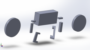
3d-image-of-biped

3D modeling

Wheels

Wheels added to the Biped will help the robot turn right and left. One foot will remain stationary on the the ground while the second foot will slightly be elevated in the air. The wheel attached to the foot that is still on the ground will rotate backwards and turn the biped in the direction of whichever foot is on the ground. For example, when the biped is on the left foot it will turn left and when the biped is on the right foot it will turn right.

Body

The final body design dimension is yet to be finalized. However the body width will be larger than the body height. This goal is to keep the body close to the ground as possible.

Legs / Feet

The feet will be connected to the body through the leg parts. Although the final design dimensions have not been chosen, the feet itself will be larger than the width of the body to prevent it from loosing stability.

Preliminary Design Document – Prosthetic Arm (Fall 2016)

By:

Carolina Barrera (Mission Objective, Creativity, WBS, Budget)

Luis Martinez ( Requirements, WBS, PBS)

Fabian Suske (Electronic and Control System)

Forrest Pino (Mechanical Design)

Hector Martinez(Mechanical Design).

Table of Contents


 MISSION OBJECTIVE (by Carolina Barrera, Project Manager)

Amputees are part of the aftermath in any warfare. When soldiers return from their mission with disabilities or missing one of their extremities, it is challenging for them to adapt to a new lifestyle. Technology has advanced far enough as to offer them an opportunity to get back to some of their previously regular activities using a prosthetic limb. In our specific case we have a soldier with a missing arm, and our mission – in conjunction with the Prosthetic Hand group in the other class, is to design and engineer a device that will help him/her perform an independent task as to eat a Quarter Pounder with Cheese meal by himself/herself.

To provide a better understanding to the reader and to avoid any confusion, a couple of definitions need to be provided at the beginning of this document. Hence, The Prosthetic Arm is defined as the device going from mid-bicep and continues down the arm until the point of integration with the Prosthetic Hand. The prosthetic Hand will be addressed as the device from the point of integration with the Prosthetic Arm down the metacarpals and including the fingertips. Finally, we will refer to the Upper-limb prosthetic system to the conjunction of the two projects, The Prosthetic Arm and The Prosthetic Hand.

 CREATIVITY

All brainstorming and brainwriting ideas were done to come up with potential solutions for inconsistencies and possibly complications with the design. You can read on our approach and previous and future concerns in the following link:

https://drive.google.com/drive/u/0/folders/0B7_Bk0we7jCYS3R6SjBYOUYwVn

REQUIREMENTS:

 LEVEL 1 PROGRAM/PROJECT REQUIREMENTS (by Carolina Barrera and Luis Martinez, Project Manager and Systems Engineer)

To satisfy the expectations of our customer, a team of engineers came up with a set of requirements from our end describing components and processes that are needed in order to excel in customer satisfaction at the delivery of our finalized product:

  1. The Prosthetic Arm shall operate together with the Prosthetic Hand to complete the mission, as components of the Upper-limb Prosthetic System.
  1. The Prosthetic Arm should have a range of motion localized at the elbow of (at least) + 60 degrees and – 90 degrees in the vertical axis, allowing the user to pick up individual food components of a meal, for consumption.(http://www.webmd.com/first-aid/bones-of-the-arm) and https://www.umc.edu/uploadedFiles/UMCedu/Content/Education/Schools/Medicine/Clinical_Science/Orthopedic_Surgery__Rehabilitation/Sports_Medicine/BiomechanicsoftheElbow.pdf
  1. The Prosthetic Arm shall have the capacity to operate for 20 minutes, based on the American average time per day spent statistics for “eating and drinking”. (http://www.bls.gov/news.release/atus.t02.htm Based on medium sized burger, fries, and drink components.)
  1. The Prosthetic Arm shall be able to lift the weight of the Prosthetic Hand and the weight of each individual McDonald’s Quarter Pounder with Cheese food item, in addition to its own weight.  (http://calorielab.com/restaurants/mcdonalds/1 Estimated dividing by three meals per day, and rounding.)
  1. The Prosthetic Arm must be controlled by the soldier independently.
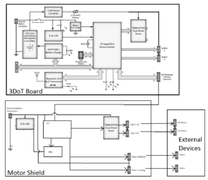
  1. The total cost of the Prosthetic Arm project shall be below $500.
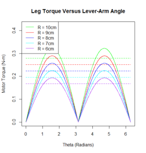
  1. The project shall be completed by the end of Fall 2016- end of academic semester for the California State University, Long Beach.(https://web.csulb.edu/divisions/aa/calendars/documents/2016-2017AcademicCalendar.pdf)
  1. The Project shall fit in one of Professor’s Hill room cabinets, hence its maximum dimensions should be determined by the dimension of the cabinet.

LEVEL 2 SYSTEM/SUBSYSTEM REQUIREMENTS (by Luis Martinez, Systems Engineer)

L2-1 (Duration) The duration of the meal time permitted by the Prosthetic Arm shall begin upon the Prosthetic Arm first making contact with the selected food item from the McDonald’s Quarter Pounder with Cheese meal.


Explanation:  To allow an amputee using the Prosthetic Arm 20 minutes of time to engage in consumption of a McDonald’s Quarter Pounder with Cheese meal, there must be a quantifiable start point for taking time, which is thus defined at the moment contact through the prosthetic is made with the respective meal component of choice.


L2-2 (Power Capacity) The battery system for the Prosthetic Arm shall have a minimum capacity of 1500 mAh.


Explanation:  Based off an estimated current draw of 4.5A from the Prosthetic Hand and Prosthetic Arm power systems combined, a meal duration of 20 mins. yields a preliminary calculation for a 1500 mAh capacity requirement (http://www.powerstream.com/battery-capacity-calculations.htm)


L2-3 (Weight Capacity):  The Prosthetic Arm shall have the capacity to lift 5.49 lbs. ± 1.34 lbs.


Explanation:  The Prosthetic Arm will be responsible for lifting the weight of the Prosthetic Hand, the weight of each individual food item from the McDonald’s Quarter Pounder with Cheese meal respectively, and its own forearm weight.  Based on an average soldier’s combined forearm and hand weight of 3.8912 lbs. (men and women combined), calculated from average soldier weights and corresponding total body weight percentages for forearm and hand respectively, and the weight of the heaviest individual food item from the McDonald’s Quarter Pounder with Cheese meal (1.52917 lbs. for 21 fl oz Coca-Cola soft drink).

Drink Weight (21 fl oz):  1.5917 lbs. for Coca-Cola (1.3692 if water), derived from respective densities

Burger Weight (7 oz):  0.4375 lbs.

Fries Weight (4 oz.):  0.25 lbs.

Average Soldier Weight, Forearm + Hand (1.765 kg ± 0.61 kg):   3.8912 lbs. ± 1.34 lbs.

Weight Capacity = Heaviest Food Item (1.5917 lbs.) + Average Soldier Weight, Forearm + Hand (3.8912 lbs.) = 5.49 lbs. ± 1.34 lbs.

http://chemistry.elmhurst.edu/vchembook/121Adensitycoke.html

http://calorielab.com/restaurants/mcdonalds/1


L2-4 (Torque) The motor for the Prosthetic Arm shall be rated for a minimum torque output of 10.634 Nm.


Explanation:  Following a weight capacity requirement for 5.49 lbs. ± 1.34 lbs. (2.49 kg ± 0.6078 kg), and assuming an arm length of 14 in (35 cm), the torque requirement is estimated as follows:

figure-3-1-therefore-a-motor

L2-5 (Control) The Prosthetic Arm shall acquire input from sensors that detect bicep movement in the vertical plane.


Explanation:  In order to achieve the mission objective of allowing an amputee with a prosthetic arm to eat a McDonald’s Quarter Pounder with Cheese meal, the arm must have the degree of freedom in the vertical plane (assuming the Earth’s surface as a reference X-Y plane).  Following a L1 requirement for the arm to be controlled through biological signals, it is imperative that movement in the bicep be detected as this muscle allows movement in the defined vertical plane of interest.

BREAKDOWN STRUCTURE:

 WORK BREAKDOWN STRUCTURE (by Carolina Barrera and Luis Martinez, Project Manager and Systems Engineer)

By the end of the Fall semester we should have completed a functional and somewhat polished prototype of a prosthetic arm. In order to meet our goal, we need to work and accomplish simpler tasks from smaller components, so that later in the semester these small parts can be integrated into the bigger, and more complex project. In other words, we need to break down the work into manageable sections so the subsystems can be working in parallel as much as possible. Figure 1 is the Work Breakdown Structure developed by Systems Engineer, Luis Martinez and Project Manager, Carolina Barrera.

wbs_visio

Figure 2- Work Breakdown Structure Diagram

PRODUCT BREAKDOWN STRUCTURE (by Luis Martinez, Systems Engineer)

Similar to the WBS, there is the Product Breakdown Structure. The PBS breaks down the bigger components of the system into smaller pieces that can be built and tested in an initial phase of the project, and later integrated to other subsystems to come up with the overall system as a result. The Product Breakdown Structure is:

pbs_visio

Figure 3 – Product Breakdown Structure

BUDGET

The estimated budget is presented below. We have omitted Ground Shipping and taxes because we are waiting on getting our material approved so we can buy them. For now, it would be wise to round up our number and we agreed on a margin of $100 in case of an accident and also in case we have to pay for 3D printing. This is how we came up with the budget of no more than $500 for the Robotic Arm project.


estimated-budget_1st-iteraation

Table 1 – Estimated Budget (First Iteration)

ELECTRONICS AND CONTROL SYSTEM (by Fabian Suske, Electronics and Control Engineer )

BASIC CONCEPT

A brief brainstorming about the prosthetic arm came to the conclusion that biomedical signals (bio signals) shall be used to control the arm. The two kinds of bio signals are EMG (Electromyography) and EEG (Electroencephalogram). The following research showed that both methods would be possible to implement. There are projects available which utilize each signals. But the hassle to get good EEG signals is much bigger then to get good EMG Signals.

Another aspect that came up in the brainstorming was the high precision needed to reach the target of feeding the soldier. Since servos were restricted to use. The focus led to stepper motors. Stepper motors are due to their mechanical construction very precise.

This ideas led to the following basic concept (figure 3):

figure3

Figure 3 – Basic Concept (Electronics)

EMG Signals are acquired by the MyoWare Sensor Shield. The signals are then send to the Teensy 3.2 MCU. There the signals are processed. The Teensy drives then the designated stepper motors. The motor for the “lifting” action is located above the elbow and is directly connected to the Teensy. The second motor used for radial movement is located below the elbow and is driven by the MKR 1000 MCU. This MCU has Wifi Capability onboard. This allows the system to be remote controlled (as a plan B). The MKR 1000 is also in charge of the power distribution (not included in this graphic). The two MCUs will communicate between each other.

References:

The project requirements state that a Quarter Pounder with Cheese meal shall be consumed. Based on this information we can measure the weight that has to be lifted.

Burger: 196 g.

Soda: 1.369 lbs.

Fries: 142 g.

The heaviest item is the soda with 1.369 lbs. The Hand subsystem stated that their subsystem shall not be heavier than 3 lbs. The weight of the arm itself shall not exceed ¾ lbs. With an allocated weight of 1 lbs. to the electronics the part of the system is around 6lbs. Since estimations were made a margin of 1 lbs is added. So the total adds up to 7lbs (3,17kg).

With an estimated length of the arm of 35cm (14 in) the motor has to deliver a torque of more then 10,8815 N

figure-3-1-therefore-a-motor

Therefore a motor with at least 10,888Nm is required.

Most stepper motors (in our budget) output a torque of 1.5-3NM. So a gear must be used to achieve the needed torque.

Since stepper motors operate at 12V and the MCUs run at less than 5Vs it is not possible to operate them directly of the MCU. Hence a stepper motor driver (stepper driver) must be used.

The stepper driver should be a Surface Mounted Device (SMD, SMT (Technology)). Also the motor should be controlled used with Step and Direction. This type is easy and simple and is sufficient. Therefore the Allegro A4988 stepper driver has been chosen. This driver operates on 3-5.5V and drives motors at 12 VTo limit the thermal output the driver will be operated at under 1 A Load Current.

Therefore the Phidget PHI-3321 stepper motor has been chosen. It operates at 12V and draws a maximum current of 670 mA

figure4

Figure 4 – Stepper Motor for the Elbow

The smaller motor used to rotate the wrist or elbow must still be TBD, but should require less current than the PHI 3321 since less torque is required.

Reference:

POWERTRAIN:

Since the Upper-limb Prosthetic System should work together as a system a common powertrain will be used. Since the space in the hand is limited the powertrain will be implemented in the prosthetic arm.

Based on the given requirements the powertrain can be dimensioned. The Hand needs up to 2.5A on 12V as well as up to 1A on 5V The MCUs operate at 3.3V but can be powered with 5V.

So the prosthetic System needs two Voltage Levels to power the System.

On the 12V level 700mA (peak) each for the steppers and 2.5A (peak) for the Hand sum to a total of 3,9A. On the 5V side the Hand requires 1A and the MCUs in the Arm need an estimated current of 200mA.

To provide 5V without a second power source a 12-5V buck converter will be used. This will add around 500mA to the 12V rail. So the 12V rail must provide 4,4A (peak).

Given this specification the Microchip MIC29502 LDO Voltage regulator has been chosen. This LDO has an enable pin so the 12V can be completely shut off. This provides some interesting efficiency features.

The fact that this LDO can be sampled for free is a plus.

To provide 5V 1A a buck converter will be used due to high efficiency compared to a LDO or fixed Voltage regulator. This also minimizes the head that will be dissipated.

The Linear Technologies LT3971A Buck Converter provides 1.3A continuous Current (up to 2A peak)

This Chip could also be sampled for free.

To power the 12V LDO 14,7V Li-Po Batteries will be used. Li-Pos are wildly available since they’re common in the RC market. 14.7V is the next higher available Voltage above 12V. A higher voltage is required by the LDO.

The size of the batteries has to be more than 1500mAh since the prosthetic system will drain around 4.5A and the time has to be 20 mins minimum. The size of the battery is TBD by the weight and volume that can be allocated to it.

References:

 SENSOR:

The MyoWare EMG has been chosen to rapid prototype because it’s widely used.

The sensor operates between 2.9 and 5,7V and connects to an analog pin on the MCU. The input voltage will be outputted to the analog pin so if you supply it with 5V and connect it to an MCU that operates at 3.3V it will cause damage to it.

To achieve better results in distinguishing the different movements two or more sensors will be used.

figure5

Figure 5 – MyoWare Test with Arduino MKR1000


References:-

system-block-diagram

Figure 6 – System Block Diagram

Given this components the complete System Block diagram is shown in “Figure 3 System Block Diagram”.

The two MCUs are used to reduce the cable tree between the upper arm and the forearm. Since only Power and the I2C Interface must run between (instead of individual cables for the Sensors and Motors).

The Teensy MCU will be located in the upper arm since it is the smaller board. (In the upper arm is less space available.

The MKR 1000 with the Wi-Fi capability will be located in the forearm.

The I2C Interface will connect the two MCUs to allow communication.

References:

MECHANICAL DESIGN (by Forrest Pino, Manufacturing Engineer)

The prosthetic arm project will stem from multiple design ideas and will incorporate the key components that will make this project a success. The prosthetic arm project will utilize modified .stl files from the open source robotics project, InMoov, in order to satisfy the requirements. The provided forearm files will be edited in order to accommodate the robotic hand that will be attached to the prosthetic arm. The .stl files for the forearm will experience most of the modification and will mostly be a guide for the prosthetic arm. Fig. 7 was provided by the InMoov project site and shows the out layering of the forearm. The forearm coverings may be removed completely or modified in a way that shows the internal structure of the arm.

figure7

Figure 7 – Basic Design for the Prosthetic Arm

figure8

Figure 8 – Inside the Forearm Structure

figure9

Figure 9 – Forearm and Elbow Assembly


Fig. 8 and Fig. 9 are internal housing designs provide by the InMoov open source project. The InMoov project made use of servos in the forearm while the prosthetic arm group will not be doing the same. The component housing structure for the InMoov design will most likely be removed.
The robotic hand project will not be utilizing the hand designs from the InMoov so integration between the two will be a custom design. The length of our forearm will also be determined by the specifications of the robotic hand. In order to counteract the weight of the arm, the forearm will be shortened as to not overload the DC motor with excessive leverage. One method of reducing weight will be editing .stl files so that less surface area will be printed and structural integrity will remain intact.

figure10

Figure 10 – InMoov design for Forearm

The InMoov site provided Fig. 10. The image shows and labels each part that was utilized in the InMoov design for the forearm. Since the forearm length may be reduced greatly, the only components that may be utilized will be the ones closest to the elbow. The Prosthetic Hand project will be in charge of creating the wrist so the components associated with the wrist in the InMoov design will be removed.

The methods of power and control for the prosthetic arm will differ greatly from the InMoov project. The degree of alteration means that the housing of the internal components will need to be custom. Depending on the size of the forearm, most of the components may need to be housed in the bicep of the prosthetic arm. The mechanism in the bicep that relates to extensions and contractions may not be suitable for our design and can be supplemented for system that utilizes a pulley. Utilizing a pulley could produce less friction than the InMoov design and would provide space for the PCB and other components. If a pulley were to be used, a mounting bracket would be needed for the motor. During research, an .stl file was acquired that would provide insight as to how mounting of the motor would be applied to the bicep.

Since an amputee will not be able to assist, a stand will be developed for testing and demoing. The current design will utilize PVC pipe and a hinge mechanism that will simulate shoulder movements. The stand will allow the prosthetic arm to hang in an orientation that would be similar to an amputee with a prosthetic arm. For demoing purposes, a member of the group will be able to guide the shoulder movements of the prosthetic arm while the other members demonstrate the effectiveness of the artificial limb.

figure11

Figure 11- Interconnection of the forearm and bicep

Figure 11 displays the interconnection of the forearm and bicep. The servos used in the InMoov design exceed the capabilities of the DC motor that will be utilized. This may lead to an alternate design that would provide movement to the forearm through a pulley system.

Refences:

SPECIAL ASSIGNMENTS AND DUE DATES: (by Hector Martinez, Manufacturing Engineer)

Design and Unique Task

  • Meet with Prosthetic Hand to ensure proper mating of hand and arm(9/20/16)
  • Analyze InMoov prosthetic arm design and look to modify and simplify for our mission objective (9/21/16-9/28/16)
    • i.e. no need to house strings and motors in forearm based on preliminary Prosthetic Hand design(Instructables: TACT Low-cost, Advanced Prosthetic Hand).
    • Modify InMoov heavy duty bicep design to fit our mission efficiently.
  • Look into design modifications to lighten system weight (9/21/16 – 9/28/16)
    • Trade-off study in materials (weight vs cost)
    • Search for design techniques to reduce weight. i.e. cutting a pattern into the shell
  • Study, analyze, and take apart existing prosthetic arm in ET-111 Lab (9/21/16-9/28/16)
  • Look into cost effective design for a stand to hold prosthetic arm, as well as provide limited movement. (9/21/16-9/28/16)
  • Study gearing, gear ratios, and gear options (9/21/16-9/28/16)
    • Trade-off study between off the shelf gears and 3D printed


NOTE:

Our 2×2 picture was taken from:

http://inhabitat.com/inmoov-is-an-open-source-3d-printed-humanoid-robot/inmoov-3d-printed-printer-robot-open-source-gael-langevin-face/

Since our project structure is going to be based on the InMoov arm.