Executive Summary
By Bao Loc Doan (Project Manager)
Program Objective
When humans manually pick up and place down surface mount components onto a printed circuit board (PCB), there are normally problems with efficiency. A surface mount component may be placed at the wrong spot or dropped. These mistakes cost the user money as well as time. An answer to those problems is a pick and place SMD machine. A pick and place surface mount device (SMD) is an automated device that can populate a PCB with surface mount components (resistors, capacitors, and IC chips) by referencing an EAGLE PCB file through the use of software. The pick and place SMD machine will be able to pick up the surface mount technology (SMT) components from 8mm reel feeders and an integrated circuit (IC) tray and place the components down at the correct location until the board is finished. The pick and place machine will replicate the error specifications of an industrial machine. The customer has expressed the desire to keep the budget of the project below $650 and finished before the end of Spring 2016.
Mission Profile
Once an EAGLE PCB file provided by any project from EE400D up until Spring 2016 is uploaded, the pick and place SMD machine shall begin populating SMT components from four 8mm reel feeder channels and one IC tray onto the PCB. The smallest SMT component that will be placed is component size 0603 (*the smallest possible component that the pick and place machine can pick up is 0402 component size*) and the heaviest component will be the ATmega32U4. One surface mount component will be rotated 45 degrees relative to starting position and be placed at a specified location. This process will repeat for 90 degrees, 135 degrees, and 180 degrees of rotation. The pick and place SMD machine will be modified from a Makeblock XY plotter and replicate the error specification of 0.05 mm (Madell Corporation Model DP2006-2).
Level 1 Requirements
These requirements provide traceability to the program objectives and mission profile. We created each requirement to be quantitative and be able to flow into system and subsystem requirements.
- The SMD pick and place machine shall pick up and place down all SMT components provided by any EE400D PCB up until the end of Spring 2016.
- The SMD pick and place machine shall be modified from an XY Plotter to have the same error specification of Madell Corporation Model DP2006-2 (n.d).
- Software for the SMD pick and place machine shall accept all EAGLE PCB files of EE400D projects up until Spring 2016.
- The SMD pick and place machine shall have four 8mm reel feeders and one IC tray.
- SMT component size 0402 shall be the smallest component that the pick and place SMD machine can pick up.
- ATmega32u4 chip shall be the heaviest component that the pick and place SMD machine can pick up.
- Total cost of finished project must be under $650.
- Deadline to complete the pick and place SMD machine shall be before the end of Spring 2016.
The Design
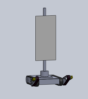
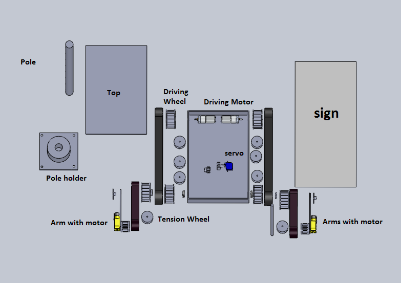
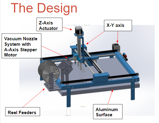
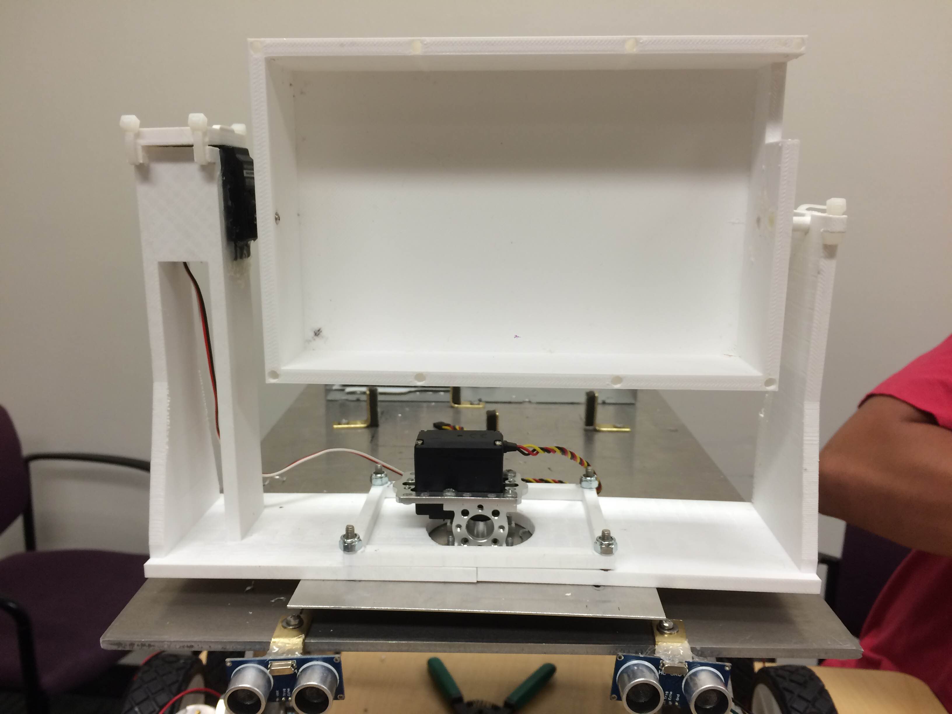
In order to have a clear understanding on how to proceed with the implementation stage, all of our systems and subsystems design needed to be complete. During this process, we had to create 3D models in Solidworks and decide what functions our machine should have in order to satisfy our requirements. The figure below will be the Solidworks model encompassing the systems and subsystems. There will also be an explanation for each subsystem and the project features that this pick and place machine has.

Figure 1 – Systems/Subsystems Model
The major systems and subsystems are the Z-axis actuator, automated reel feeders, vacuum nozzle system with A-axis stepper motor, aluminum surface, and XY-axis linear movement.
Z-Axis Actuator
This subsystem will control the “up and down” movement of our pick and place machine. A standard sized nema 17 Makeblock 42BYG stepper motor will control a threaded rod which has a bar attached to it was the base for our vacuum nozzle system. The original kit that was purchased is called Makeblock Thread Drive pack. We also had the height of the actuator cut due to the unnecessary large size of it. We found that our nozzle will shake when our Z-axis was in operation; therefore in order to eliminate approximately 80% of the shaking movement, we had to attach a rubber band to our nozzle. Due to this error, we decided to redesign our Z-Axis actuator. By using a linear slide actuator, we were able to completely eliminate all shaking of the nozzle caused by our previous thread drive kit. More information is provided in the mechanical design section.
Vacuum Nozzle System with A-axis Stepper Motor
A bracket was designed in order to hold a standard sized nema 17 Makeblock 42BYG stepper motor which will control the A-axis rotation of components. A 4mmx6.18mm rigid coupler will attach the shaft of the stepper motor to a T-connector (purchased from buildyourcnc.com) that has several nozzle fittings for 0402 sized components to IC chips. The vacuum will connect into a solenoid valve and then into the T-connector with aquarium tubing. The bracket design will be linked in our mechanical design section.
Aluminum Surface
The aluminum surface table allows the pick and place machine to have a static surface to operate on as well as the ability to attach our reel feeders, IC tray, the Makeblock XY Plotter, and origins. The aluminum surface blog will be linked in our mechanical design section.
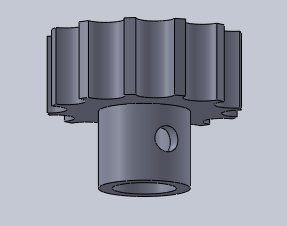
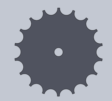
Reel Feeders
The reel feeders is where all of our surface mount resistors and capacitors are docked. An aluminum bracket was designed in order to hold four continuous micro servos. These continuous micro servos will be for reeling and holding the plastic tape so the plastic tape does not go into the working area of the pick and place machine during operation. The reel feeders will be controlled by G-code and be automated by having our vacuum nozzle tip pull the cut tape forward before every picking of a component. The reel feeder solidworks model will be linked in our mechanical design section.
XY Axis
Originally, the Makeblock XY plotter came with their standard 42BYG stepper motors, but during our PDR and CDR demos, we came to the conclusion that the steppers were too slow and inaccurate. We decided to purchase the 42BYG 5:1 geared stepper motors from Makeblock in order to fix those problems. These new geared stepper motors will control our XY axis movement and will also be controlled by G-code. A trade-off study for the geared stepper motors will be linked in our experimental results section.
G-code Interpreter
Onboard our pick and place machine will be an Arduino Uno with a Makeblock shield attached to it. There will be C++ modules that will interpret G-code which will automate our machine. There will also be a java GUI interface that the user can use to send a G-Code file to, which will automatically send every line serially to our Arduino. A more in-depth explanation will be in our software design section.
System Design
By Christine Vu (Missions, Systems, and Test) and Henry Nguyen (Electronics and Control)

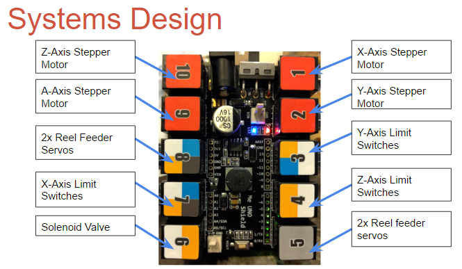
Figure 2 – Me UNO Shield Pinouts
For our machine, we used a Me Uno Shield attached to an Arduino Uno. The shield has 10 RJ25 ports. Each component for our machine is listed in the image above. All of our stepper motors are inserted into the red ports (1,2,9, and 10) which outputs 12V. More details on our Me Uno Shield can be found here:
https://www.arxterra.com/spring-2016-3d-smd-me-uno-shield-and-software/

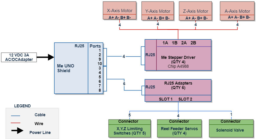
Figure 3 – Update System Block Diagram from CDR
Based on these Me UNO Shield Pinouts, we were able to map out our system, which is shown in Figure 3. From the Me UNO Shield, there are 4 Me stepper drivers for the 4 stepper motors to control our axes and adapters to convert the cables to 1-2 pinouts. We used a total quantity of 6 RJ25 adapters to attach our axis limiting switches, reel feeder servos, and solenoid valve.
Experimental Results
By Henry Nguyen (Electronics and Control)
Origins and Scaling
By Henry Nguyen (Electronics and Control)
In order for us to accurately pick and place components on our pick and place machine, we must be able to identify our origins. We have decided that the bottom left corner of any PCB to be the origin. Once we determine our origins, our reel feeders and IC tray G-Code locations will be dependent on this. Details can be found in our blog post:
https://www.arxterra.com/spring-2016-3d-smd-origins-and-scaling/
Trade-off Studies
We had to perform several trade off studies in order to validate what products we can used based on our requirements. This will also allow us to avoid any future problems caused by choosing the wrong product.
Vacuum Pump
By Henry Nguyen (Electronics and Control)
For our vacuum pump, we needed to find a cheap but reliable vacuum pump for our machine. This pump and nozzle will need to be able to pick up components as small as 0402 and ICs as large as Atmega 32U4. In order to satisfy these requirements, we were able to change an aquarium pump into a vacuum pump. The details is linked below.
https://www.arxterra.com/spring-2016-3d-smd-vacuum-pump-trade-off-study-v2/
Solenoid Valve
By Henry Nguyen (Electronics and Control)
Our vacuum needs to be able to shut off and on based on the G-Code values we input. In order to do so, we needed a solenoid valve. We found that our solenoid valve heated up very quickly to high temperatures. In order to make sure the temperature did not exceed the melting point of our plastic tubing, we performed this trade-off this study.
https://www.arxterra.com/spring-2016-3d-smd-solenoid-valve-trade-off-study/
Geared Stepper Motors
By Loc Doan (Project Manager)
We upgraded our X and Y axis stepper motors to geared stepper motors from Makeblock. Geared stepper motors allowed us to achieve the precision we needed while half stepping verses our 16th stepping from our old stepper motors. Details can be found here:
https://www.arxterra.com/spring-2016-3d-smd-geared-stepper-motor-trade-off-study/
Rapid Prototyping
For our machine, we needed to perform rapid prototyping in order to ensure that our machine works the way we want it to before purchasing parts. We used extra brackets and pieces from our X-Y plotter in order to rapid prototype. Once we ensure that everything runs properly with our software we were able to create a design of parts that we needed to get manufactured.
Z-Axis
By Henry Nguyen (Electronics and Control)
For our Z-Axis, we purchased a Thread Drive Pack from Makeblock which is able to move our thread drive beam up and down with great precision. However, we wanted to control the thread drive using a stepper motor vs the given DC Motor. In order to do so needed to rapid prototype brackets and run tests using our X-Axis software and ports. Details can be found in the link below; however, due to accuracy errors, we redesigned our Z-Axis with a linear slide actuator which can be found in the mechanical design section.
https://www.arxterra.com/spring-2016-3d-smd-z-axis-rapid-prototype/
Subsystem Design
Interface Definition
By Christine Vu (Missions, Systems, and Test)
To help us obtain the correct pinouts for our system, we decided to map out the Me UNO Shield and decide which pins we needed. Port 5 was noted as unusable due to its use of bluetooth serial communication.

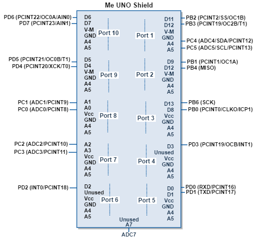
Figure 4 – Me UNO Shield Pinout
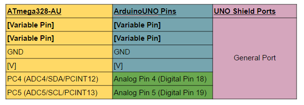
Each port has a general format and has 1-2 analog/digital pinouts. Figure 5 shows the general format for a Me UNO Shield port. On the left side is our microprocessor pinouts, ATmega328. The middle column indicates the pinouts for our microcontroller, which was the UNO. The right are the RJ25 connector ports for our Me UNO Shield. One port contains 6 pins, each for I2C communication, which we did not need to use, Vccm, ground, and 1-2 analog/digital pins.

Figure 5 – General Port for Me UNO Shield
Based on our system block diagram, the interface definition indicates which specific pins were used for the subsystems — stepper motors, limiting switches, reel feeders, and solenoid valves.
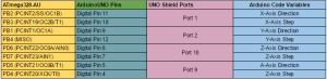
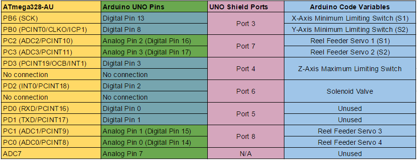
Figure 6 – Stepper Motor Controls
The Arduino Code variables in Figure 6 were originally based on the Makeblock X-Y Plotter Robot Kit code, but had to be modified due to switching from the Makeblock Orion to the Me UNO Shield.
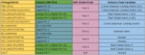
Figure 7 – Reel Feeder, Limiting Switch, and Solenoid Valve control
As shown in Figure 7, most of the ports hold two different analog/digital pinouts, so the limiting switches, reel feeder servos, and solenoid valve controls were grouped. The two ports, Port 4 and Port 6, are shown with only one digital pin, so we decided to go with the solenoid valve and one of the limiting switches.
Hardware Design
The mechanical designs were generated based on the project’s subsystems, which were the aluminum surface, X,Y,Z,A – Axis and origin brackets, Z-axis thread beam, and z-axis linear slide actuator.
Aluminum Surface Table
By Henry Nguyen (Electronics and Control)
Our pick and place machine required an aluminum surface table in order to place our PCB, reel feeders, and IC tray. This surface table will allow us to have a flat surface in order to pick and place components. Details on the design of the aluminum surface table can be found here:
https://www.arxterra.com/spring-2016-3d-smd-aluminum-surface-table/
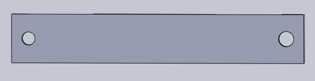
X, Y, Z, A -Axis and Origin Brackets
By Henry Nguyen (Electronics and Control)
Since our machine is first of its kind for EE400D, we had to create everything from scratch that was not purchased from Makeblock. Since we had to customized our machine, we needed new brackets with exact drilling in order to attach our X, Y, Z, and A-Axis stepper motors. We also had to manufacture a bracket to hold our PCB in place. Details can be found here:
https://www.arxterra.com/spring-2016-3d-smd-x-axis-y-axis-z-axis-a-axis-and-origin-brackets/
New Z-Axis Thread Beam
By Henry Nguyen (Electronics and Control)
We found that our current thread beam on our Z-Axis thread drive would cause a lot of accuracy error. This beam would wiggle a lot because the holes on it is slightly too large meaning our 4mm rod became too small. The thread beam will now tilt forward due to the weight of our A-Axis stepper motor. Now that the thread beam is tilting forward, it caused more friction on our 4mm rods forcing our stepper motor to stall. A new design of our thread beam can be found here:
https://www.arxterra.com/spring-2016-3d-smd-z-axis-beam/
Z-Axis Linear Slide Actuator
By Henry Nguyen (Electronics and Control)
After testing our Z-Axis thread beam, we found that although our accuracy greatly increased from before, we would still have some accuracy issue when our beams moves up and down. When moving down our nozzle would shift to the left and when moving up the nozzle will shift to the right. This was not a major problem because although the nozzle will shift to the left when moving down, it will always shift in the same position towards the left every time. Although we would still be able to pick up components, we wanted our machine to be accurate and have a smooth linear movement. We decided to purchase a linear slide actuator using a lead screw. Details can be found here:
https://www.arxterra.com/spring-2016-3d-smd-z-axis-linear-slide-actuator/
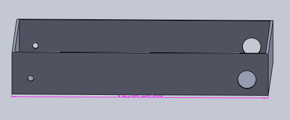
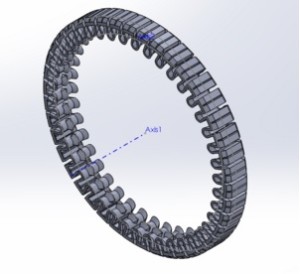
Creating an Automated Reel Feeder From Preliminary Design
by Nasser Alsharafi (Manufacturing)
The basic design included the fabricating of an aluminum base, and axle to dispense SMD parts. I tried to go into detail of the design by figuring out how to automate the reel feeder without adding too complex of a system design to the project. This included the addition of a servo platform, four servos, and channels for the tape to run through. The servos were chosen to rotate many times in order to collect the tape and move the tape at the same time. The servos were positioned on a custom fabricated platform at a 45-degree angle to optimize the tape peeling off and disposed of into four spools attached to the reels. This method worked much more efficiently and simply than the other designs, and fully automated the reel feeder after programming.
https://www.arxterra.com/spring-2016-3d-smd-reel-feeder-bracket/
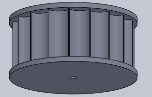
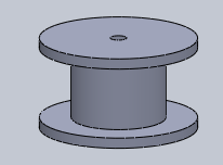
Designing a Universal IC Tray
by Nasser Alsharafi (Manufacturing)
The developments of the project lead to the need to create an IC tray with universal chip, and part sizes. I designed an IC tray from ABS plastic material by exporting a Solidworks file to a 3D printer. It is critical that the Tray can successfully contain the main ATMega32U4 IC, as well as other widely used IC sizes. The tray features 21 compartments described in detail in the link below. The IC tray needed to be designed to be small enough to save real estate on the machine table. It also needs to be less than 0.3 in height from the table so that the machine only lifts a maximum amount of 0.3 inches on the Z – axis. This I was able to configure in order to make the machine speed more efficient.
https://www.arxterra.com/spring-2016-3d-smd-ic-tray/
Software Design
The initiation of our machine is when one line of G-Code is sent serially to the Arduino. If there is data, then the process will begin deciphering which type of control we would like to the machine to output, such as checking whether to turn on the solenoid valve, activating a rotation for the reel feeder servo, or moving to a coordinate. Figure 8 is the general process for our software.
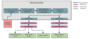
Figure 8 – Software Block Diagram
Arduino Coding
By Christine Vu (Missions, Systems, and Tests) and Henry Nguyen (Electronics and Control)
Our arduino software has 4 modules: G-CodeParser.ino, process_string.ino, stepper_control.ino, and move_reel.ino. G-Codeparser.ino, process_string.ino, and stepper_control.ino are modules obtained from Makeblock, which is an open source company. Since we used their X-Y Plotter Robot Kit as our baseline of our project, we used their software. In order to adjust the software to our needs, we wrote codes several modules. We included an off and on switch for our solenoid valve, four reel feeder servos, and two new stepper motors. More information on how our software was modified can be found here. It includes flowcharts and explanations for each module we modified and created:
https://www.arxterra.com/spring-2016-3d-smd-software/
Java
By Henry Nguyen (Electronics and Control)
For our machine, we had to tap into the Java code for our GRemote.gui in order to initialize our X, Y, and Z-Axis stepper motors and limiting switches. Details can be found here:
https://www.arxterra.com/spring-2016-3d-smd-me-uno-shield-and-software/
Conversion of Eagle file to G-Code
By Christine Vu (Missions, Systems, and Test) and Henry Nguyen (Electronics and Control)
One of the main requirements for our machine is to be able to receive an Eagle board file and convert it into G-Code in order to know the proper locations of where we need to place our components. We found that we can convert Eagle to DXF and from DXF to G-Code. Details can be found here:
https://www.arxterra.com/spring-2016-3d-smd-conversion-of-eagle-file-to-G-Code-initial-process/
Verification & Validation
By Christine Vu (Missions, Systems, and Test)
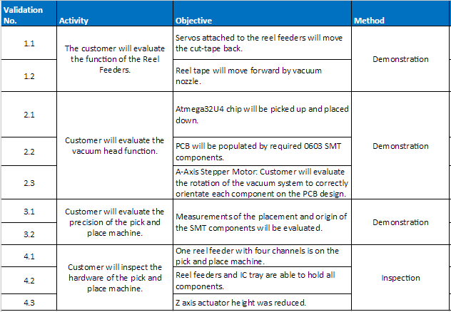
The Validation matrix created was based on the program objectives and the goals that the customer wanted the team to achieve. Below is a list of functions our machine performed for the customer to evaluate.

Table 1 – Validation Matrix
Verification tests were conducted to reflect the requirements on the physical design of the SMD pick and place machine. A list of procedures were presented in the verification test plans. Details and results are found here:
https://www.arxterra.com/spring-2016-3d-smd-verification-test-plan/
Project Update
Work Breakdown Structure
By Bao Loc Doan (Project Manager)
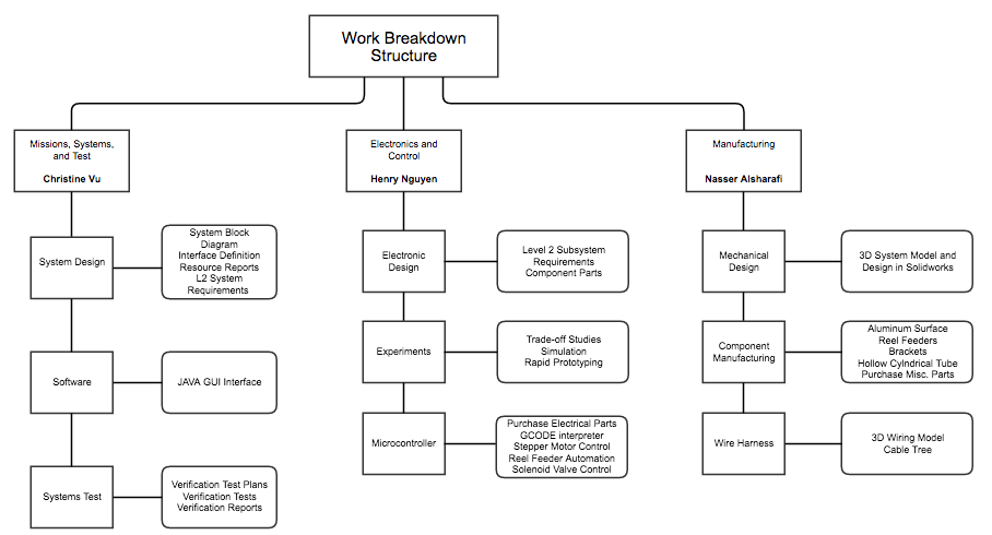
A work breakdown structure was essential to the completion of the project. The WBS allowed each engineer to understand their roles and what tasks they needed to focus on completing. Our WBS had several iterations as the semester went on and each iteration there would be something new added or revised. This was necessary because there were some things that were missing and some new design ideas that were implemented. The final pick and place SMD machine WBS will be shown in the figure below.

Figure 9 – Work Breakdown Structure
Resource Reports
Mass Report
By Christine Vu (Missions, Systems, and Test)
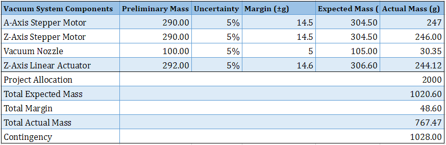
The purpose for our mass report is to assure that the weight on the Z-Axis would not possibly obstruct the progress of picking and placing. Since the Z-Axis was on the X-Axis rods, we considered the weight on the X-Axis. The project allocation of 2000g is from a rough test we conducted by placing a heavy object, which was approximately 2000g, and determined that this the motors almost began to stall. Table 2 indicated that our actual mass was 767.47g, which is two times less than our allocated mass.
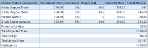
Table 2 – Finalized Mass Report
Power Report
By Christine Vu (Missions, Systems, and Test)
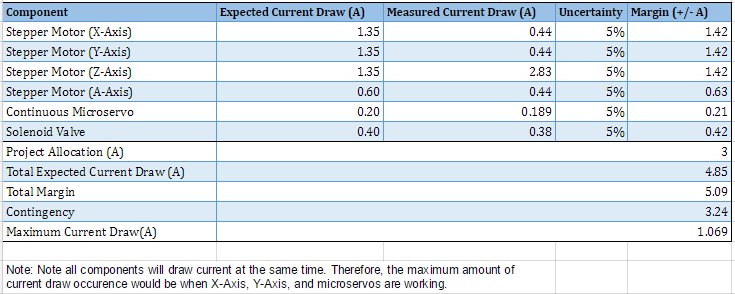
Our resource for power is limited by the CSULB’s power lines and our power adapter. It is important to note that the actual current draw, which is shown at the bottom, is the maximum amount that would have been drawn at one time. The Total Expected Current Draw will not be met because that would be assuming each component/subsystem is operating.
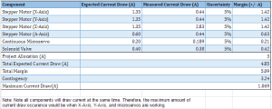
Table 3 – Finalized Power Report
Cost Report
By Bao Loc Doan (Project Manager)
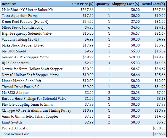
Our original allocated project budget was $650. The total cost of the project ended up being $756.94. We asked for permission from the customer each time we went over budget and got approval. A good bulk of the cost of this project was due to the need of hardware that was not readily accessible. It was tough to find any local hardware shops that could supply the parts that we needed at the price we wanted. We looked on McMaster Carr but their prices were much too high for our budget (~$37 dollars per coupler). Anything we bought from Makeblock or Pololo shipped from China, and this resulted in high shipping costs. The cost report will be linked below.
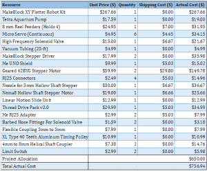
Table 4 – Finalized Cost Report
Project Schedule
By Bao Loc Doan (Project Manager)
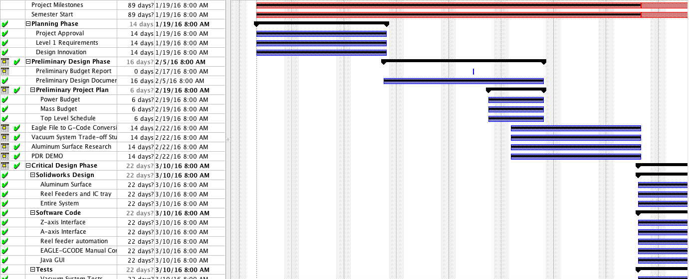
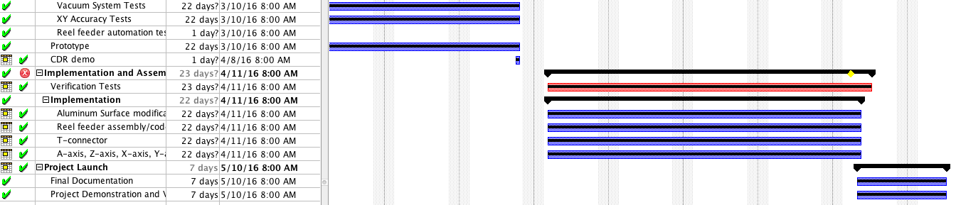
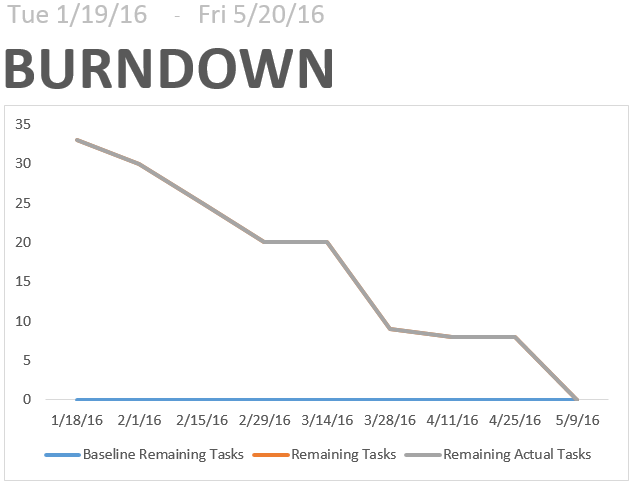
We were able to successfully complete our project schedule by the end of the semester. Our project schedule and Gantt charts were created in ProjectLibre. We were able to export our ProjectLibre schedule file later to Microsoft Project to produce burndown graphs and the project overview. The project schedule was extremely helpful because by CDR we were behind schedule but since we knew what tasks we were behind on, those tasks were focused on and completed before we moved on.
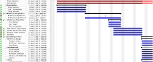

Figure 10 – Gantt Chart from ProjectLibre
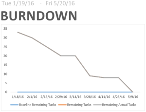
Figure 11 – Burndown Plot

Figure 12 – Project Overview of Completion
Concluding Statement
By Bao Loc Doan (Project Manager)
Although we completed all of our requirements for this semester, I feel like there are some things that can be added to improve the functionality of the device. If we had more time and resources, there are two features that we would like to implement onto this pick and place machine. First, we would implement a second nozzle onto the z-axis actuator that could extrude solder paste. Applying solder paste before setting the component down onto the PCB is a critical part of the success of this pick and place machine. The solder paste will allow the component to be set down properly rather than possibly vibrate out of position when the solenoid valve cuts off the flow rate from the vacuum. Second, we would implement a camera self-calibration system using an inexpensive usb endoscope. The self-calibration system will save the user a substantial amount of time as it will automatically determine the origins and error rate and self correct for the entire pick and place machine.
There are some lessons that I took away from this semester. When we first started this project, the main concern was the software. Although the software was indeed the largest issue of this project, the hardware was nearly equally as important. Understanding what parts were needed to maintain our accuracy was critical. At the end of the semester, we had the software portion of this project finished but due to janky hardware, we didn’t have the right accuracy. We went over 5 iterations of a simple z-axis beam until our accuracy was satisfactory. Another important lesson is that this project will require many iterations. Do not get discouraged by how many iterations that will eventually be redesigned and reimplemented. This was the first semester of the project so there was no backbone for us to go off on except for research we did on the internet. Sometimes what we did find couldn’t work for our needs because of the limited resources we had. Another lesson we learned the hard way was issue of miscommunication. Communication was critical in this project. During this semester, three months were spent on what was supposed to be a simple reel feeder bracket design. This was due to a communication issue between me and our manufacturing division. Once we got the issue straightened out and we received help, the bracket was finished in a weekend. Other than that, we really did enjoy doing this project. It was great seeing something come alive from the very beginning of the process to the end.
Resources
Project Video – https://youtu.be/KDmNSbDamOA
CDR – https://drive.google.com/folderview?id=0B1CO1_x-4KFOd19ESlhYejJXZHc&usp=drive_web
PDR – https://drive.google.com/folderview?id=0B1CO1_x-4KFOa1g5Nk1NMnQ0Mkk&usp=drive_web
ProjectLibre File – https://drive.google.com/folderview?id=0B1CO1_x-4KFOWTdaeXBhRXlOLVU&usp=drive_web
Verification and Validation Documents – https://drive.google.com/open?id=0B1CO1_x-4KFOWjlDZXRuS3RVSkk
Solidworks Files – https://drive.google.com/open?id=0B9oA00YQwNGMT1VzMWZpSDdjak0
EagleCad Files – https://drive.google.com/folderview?id=0B1CO1_x-4KFOSzBwZHVNY05SUzA&usp=drive_web
Arduino and/or C++ Code
*** Link was added to this blog post: http://arxterra.com/spring-2016-3d-smd-software/ ***
https://github.com/cvuchristine/MakeblockPlotter.git
Other Applications: G-Code Files –
https://drive.google.com/folderview?id=0B1CO1_x-4KFOMGpFTC11dXV1UzQ&usp=drive_web
Complete BOM – https://drive.google.com/folderview?id=0B1CO1_x-4KFONjBGMVNLMl9sMG8&usp=drive_web