Pathfinder Chassis Generation 7 Summary Blog Post
Authors:
Alexandrea Jackson (Project Manager)
Daniel Enverga (Mission, System, and Testing)
Patrik Hertle (Electronics & Control)
Christopher Fingers (Design and Manufacturing)
Approval:
Alexandrea Jackson (Project Manager)
Table of Contents
Executive Summary
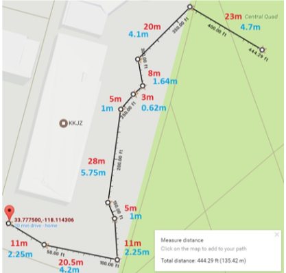
Pathfinder Chassis Generation 7 has focused creating a functional Mars Rover replica. To demonstrate the functionality of Pathfinder Chassis, an obstacle course laid out by Pathfinder Generation 5 was laid out defined in Figure 1.
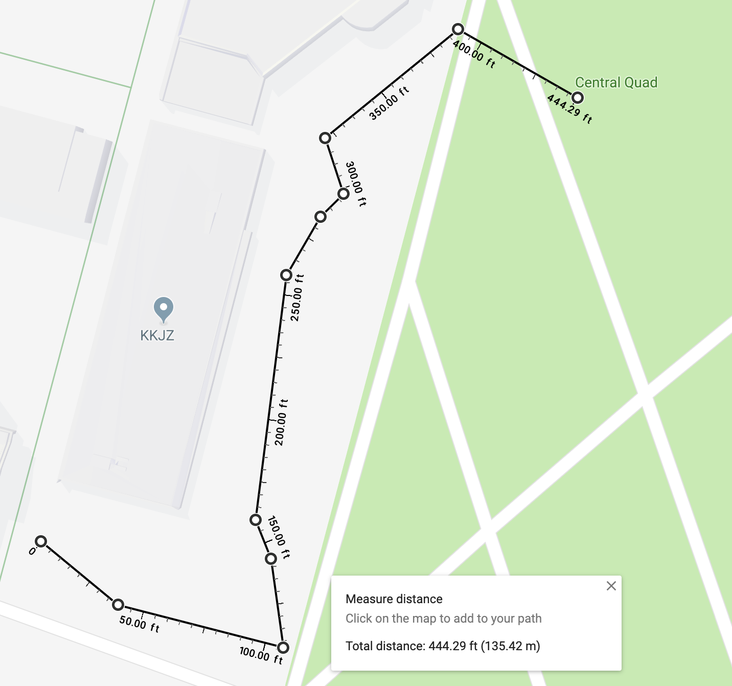
Figure 1: Final Course Outline
Program and Project Objectives
Program Objectives
The pathfinder generation 7 team will work together to create a functional robot for The Robot Company within 15 weeks (May 13th, 2019). The pathfinder will use the Arxterra Control Panel as the main interface to communicate using bluetooth.
Project Objectives
Maneuver over a simulated Mars terrain encountered on the CSULB campus predetermined by Pathfinder Generation 5. Communicate to and from pathfinder using Arxterra Control Panel using mobile device. Designed to be aesthetically similar to the NASA mars pathfinder using a rocker bogie system. The main objective of this Pathfinder generation is to make the rover functional once again. Completion of the Pathfinder Generation 7 by May 13th 2019.
Mission Profile
The Spring of 2019 Pathfinder will follow the path laid down by previous Pathfinder Generation 5. The mission will begin in front of the CSULB library. The rover will then proceed to begin its journey through campus, a 0.09 mile journey to 10 checkpoints already predefined. The 10 GPS checkpoints along the way and the rover will traverse a flight of stairs.
Project Features
Pathfinder Chassis Generation 7 main improvements include software design, PCB improvements, and mechanical improvements recommended from previous generations.
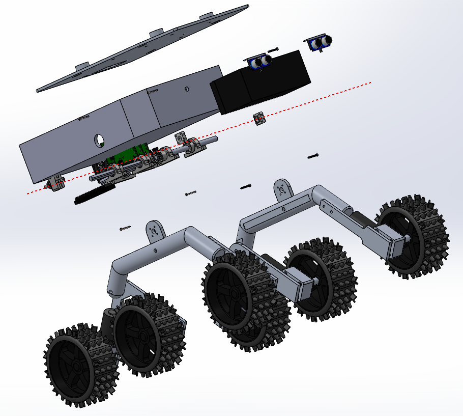
Figure 2: Exploded View of Pathfinder
Requirements
The requirements of Pathfinder Chassis Generation 7 includes more functional in level 1 and performance in level 2. These help describe the functionality and how the robot should be designed and verified in the end. The constraints on the project are provided by the university and course outline such as cost and the final date of May 13th, 2019.
Engineering Standards and Constraints
Based on the customer’s expectations and the mission objectives, we have come up with various Level 1 Requirements that are quantitative, verifiable, and realizable. This allows us to move the design process forward and obtain a clear understanding of what we are trying to accomplish.
We are in compliance with constraints on the project imposed by The Robot Company (i.e., CSULB) and Project Stakeholders. Specifically, we include University and applicable environmental, health, and safety standards and those safety standards specifically associated with the product (e.g., Children’s Toys).
Applicable Engineering Standards
- IEEE 29148-2018 – ISO/IEC/IEEE Approved Draft International Standard – Systems and Software Engineering — Life Cycle Processes –Requirements Engineering.
- NASA/SP-2007-6105 Rev1 – Systems Engineering Handbook
- Bluetooth Special Interest Group (SIG) Standard (supersedes IEEE 802.15.1)
- C++ standard (ISO/IEC 14882:1998)
- Federal Communications Commission (FCC) Relevant standards for a product implementing a 2.4GHz radio, FCC Intentional Radiators (Radio) Part 15C, and Unintentional Radiators FCC Part 15B for CPU, memories etc.
- NXP Semiconductor, UM10204, I2C-bus specification and user manual.
- ATmega16U4/ATmega32U4, 8-bit Microcontroller with 16/32K bytes of ISP Flash and USB Controller datasheet section datasheet, Section 18, USART.
- USB 2.0 Specification released on April 27, 2000, usb_20_20180904.zip
- Motorola’s SPI Block Guide V03.06
Environmental, Health, and Safety (EH&S) Standards
- CSULB College of Engineering (COE) Safety Resources. Start your search for applicable CSULB COE Safety Standards and Procedures here. Please review and acknowledge if any safety issues as defined by the COE applicable to your project. For example, the closest safety constraint for a linear actuator is for use of the Hydraulic Press located in the Engineering Technology (ET) Building Lab. Here is a link to the Hydraulic Press Safety document.
- CSULB Environmental Health & Safety (EH&S)
- IEEE National Electrical Safety Code (NESC)
- NCEES Fundamental Handbook (FE) Reference Handbook
- ASTM F963-17, The Standard Consumer Safety Specification for Toy Safety, is a comprehensive standard addressing numerous hazards that have been identified with toys. In 2008, the Consumer Product Safety Improvement Act of 2008 (CPSIA) mandated that the voluntary toy safety standard in effect at that time become a nationwide mandatory children’s product safety rule.
Disposal of Hazardous Waste including Electronic and Solar Cells
- CSULB Physical Planning & Facilities Management (PPFM) Environmental Compliance Electronic Waste Handling and Disposal Procedures. These procedures shall be followed for the disposal of all batteries.
Program Level 1 Requirements
Project/Economic
Subcategories: Cost, Extensibility, Interoperability, Maintainability, Quality, Marketability, and schedule
- The Pathfinder shall be constrained to a not to be exceed Cost of $250.
- The schedule shall be constrained to a completion date of Monday, May 13th, 2019. Project completion includes documentation and materials purchased by or loaned to the project.
- One of the Economic Factors affecting our robots are return rates.
- Surface Mount Technology (SMT) will be employed unless a waiver for through-hole parts is granted.
- Maintainability: Disassemble and Reassemble of the robot shall be constrained to less than 20 minutes (10 + 10 minutes). Disassembly: The Arduino Mega is clear of all other electronic and mechanical subassemblies. All electronic and mechanical subassemblies and associated connectors, sensors, and motors including motors are disconnected. A functional test of the robot is conducted after reassembly to confirm its functionality. All project may reference a cable tree as well as an assembly diagram as necessary. This requirement is demonstrated/verified on the last day of the schedule. Projects may request a waiver with justification.
Social and Ethical
Subcategories: Accessibility, Aesthetics, and Usability
- Accessibility by the blind and Marketability of the robots shall be implemented/enhanced by a speaker. The speaker shall generate sound effect consistent with the type of the robot.
- Wiring Aesthetics shall be nice and clean with the usage of terminal blocks, 100 mil contact pins and headers for digital, and 3.5mm & 5mm pitch for connectors handling any power. Handling Precaution for Terminal and Connector will be in compliance with JST documentation.
- To enhance Aesthetics, the robot shall be designed in such a way that there are no dangling or exposed wires. Connectors will used between all electronic and electromechanical components. Jumper wires will not be used, ribbon cables are preferred.
- To enhance Aesthetics, the form factor of a robot modeled on a real or fictitious robot shall be constrained by the original. For example, Pathfinder Chassis should be a scale model of the real Spirit and Opportunity Mars Rover. Projects may request a waiver with justification.
- Usability of the robots shall be enhanced by adding autonomous functions and/or by use of the Arxterra phone application as dictated by the assigned mission.
Manufacturability
Subcategories: Constructability, Size, Weight, and Power (SWAP)
- Constructability of Pathfinder Chassis shall be documented at the CDR and approved by the president of the TRC robot company. Constraints imposed by this requirement include the use of bushing or bearings in all moving and rotating parts. Interlocking Hinges with latching mechanism. No gaps greater than 1 millimeter, and immediate access to all external connectors (USB, switches).
- The Size of the electronics enclosure, shall be constrained to be no greater than the Arduino Mega, Main PCB shields, and associated mounting hardware.
- Power to the Pathfinder Chassis shall be provided by the 12V lead acid battery. Safety and regulation concerning lead acid batteries are followed by OSHA.
- Back of the envelope calculations and experiments shall be conducted to set the diameter of Power carrying wires. Follow the American Wire Gauge (AWG) standard when defining the diameter of power carrying wires. This work to be completed and documented by the CDR.
Environmental Health and Safety (EH&S) Standards
Subcategories: Environmental Standards, Sustainability, Toxic waste (Solar panels), Health and Safety, Ergonomics
- All standards, codes, and regulations as defined in the “Engineering Standards and Constraints” Section of this document shall apply.
Functional
- Software shall be written in the Arduino De facto Standard scripting language and/or using the GCC C++ programming language, which is implements the ISO C++ standard (ISO/IEC 14882:1998) published in 1998, and the 2011 and 2014 revisions. Required exceptions to this standard can be found here.
- All robots shall be in compliance with the Command and Telemetry Packet specification.
- All robots shall be controlled via Bluetooth 4.0 in compliance with the Bluetooth Special Interest Group (SIG) Standard (supersedes IEEE 802.15.1).
Project Level 1 Functional Requirements
1.1: Pathfinder shall navigate through CSULB course as defined by Pathfinder Generation 5 seen in Figure 1.
1.2: Pathfinder shall be able to maneuver through Mars terrain is simulated as encountered on CSULB course using a Rocker-Bogie system by stairs and an incline of terrain.
1.3: Pathfinder shall be powered using a rechargeable battery that will be interfaced with Solar Array team.
1.4: Pathfinder Chassis shall be integrated with solar array as defined in ICD via allocation of PCB interfaced with Arduino Mega and solar array enclosure.
1.5: Pathfinder Chassis shall use a pan and tilt system to hold a mobile phone to communicate remotely from ArxRobot App to Arxterra Control Panel.
1.6: Pathfinder shall update users on Chassis’ built-in telemetry and command through Arxterra Control panel such as ultrasonic, battery levels, GPS location.
1.7: Pathfinder shall update users on Chassis’ custom telemetry and command through Arxterra Control Panel such as speed summary and current summary of motors.
1.8: Pathfinder shall be able go over objects that are less than 19.05 cm (7 ½ inches).
1.9: Pathfinder shall switch to manual mode when an object is detected 30 cm ± 5.08 cm (12 inches ± 2 inches) away.
1.10: Pathfinder shall follow the form factor the Mars Rover, Spirit and Opportunity as described in Pathfinder Generation 3, with improvements to be functional maneuvering through CSULB course as defined in the mission profile.
1.11: Pathfinder shall not exceed a purchasing budget of $250 as verified in cost report.
1.12: Pathfinder shall be completed by Monday, May 13th, 2019 as defined by course outline.
Level 2 Requirements
2.1.1: Pathfinder shall traverse 19.05 cm (7.5 inch) stairs as encountered on CSULB course seen in Figure 1.
2.1.2: Pathfinder shall complete the predetermined course within 35 minutes by using motors operating at average of 8.64 RPM.
2.2.1: Pathfinder motors shall operate at at least 1.686 kgcm torque to pull the weight of chassis defined in the mass report 13.479 kg
2.2.2: Pathfinder shall operate with a counter rotation differential gear-box system to allow the pathfinder to traverse through rough, unlevel terrain as defined by Pathfinder Generation 5.
2.2.3: A 6-wheel electronic differential shall be implemented as defined in Pathfinder 5 to increase power to other motors if current of motors is too high.
2.3.1: Pathfinder’s 12 volt rechargeable battery will be able to provide 5.7 A of current for the Arduino Atmega, ultrasonic sensors, the 6 dc motors, motor drivers, and 2 servos determined by the power report.
2.3.2: A battery charge controller should be installed to charge the 12V battery.
2.4.1: The pathfinder will integrate with solar providing 4 pins on Arduino.
2.4.2: The pathfinder should be enclosed with Solar Array mounted on enclosement.
2.5.1: Servos shall operate at a torque of 0.00241 kg-cm to rotate the Tilt system with a weight of 31.1g.
2.5.2: Servos shall operate at a torque of 0.701 kg-cm to rotate the Pan system with a weight of 513.1g.
2.5.3: Pathfinder shall include a pan and tilt system mounted on top of the gear-box for use of camera viewing in which the system will be able to view 180° horizontally and 360° vertically.
2.6.1: Arxterra Control Panel shall update users via Bluetooth on GPS location.
2.6.2 Arxterra Control Panel shall update users via Bluetooth on battery levels (phone and main battery).
2.7.1 Arxterra Control Panel shall update users via Bluetooth on the current going through motors.
2.7.2: Pathfinder shall have encoders to determine the speed of the motors displaying summary on Arxterra Control Panel.
2.8.1: Pathfinder shall incorporate a mechanical stop to limit the Chassis’ Rocker Bogie system to a maximum of 60° ± 3° moving upward.
2.8.2: Pathfinder shall utilize a Rocker-Bogie system to allow an angle of at least 42.9° to traverse objects of a maximum height of 19.05 cm (7 ½ inches)
2.9.1: Pathfinder shall use ultrasonic sensors to detect obstacles ranging from 3cm to 200cm away updating users through the control panel.
2.9.2: Pathfinder shall switch in manual mode to be controlled by control panel when objects larger than a minimum height of 19.05 cm (7 ½ inches) is detected at 30 cm ± 5.08 cm(12 inches ± 2 inches) away.
2.10.1: Pathfinder shall be less than width of a 3 feet to fit through standard doorways.
2.12.1: the Pathfinder shall complete the CSULB course by Monday May 13th, 2019 as defined by course syllabus.
For our derived requirements, we looked at tracing level 2 requirements to one main level 1 requirement as numbered above. However, most of the level 2 requirements can be traced back to multiple level 1 requirements as seen in the figure below.
Allocated Requirements / System Resource Reports
Allocated requirements, also known as resource reports, are written and tracked by the System Engineer. The types of resource reports are based on the project. For example, power allocation/estimate for each subsystem module of a spacecraft would be important, while a more loose tracking for a toaster would be in order. Each resource should have a margin attached to it based on the uncertainty in the estimate. It should also show contingency, where contingency is defined as the project allocation minus the estimate plus total margin.
The following is the mass report for the overall mass report of the Pathfinder Chassis. The estimated weight was based off of the values of the Pathfinder Chassis Generation 6 mass report. The actual weight was physically recorded using a scale.
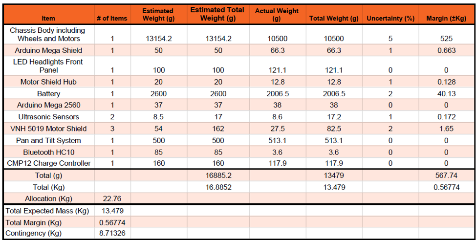
Figure 3: Mass Shared Report
The following is the power report for the Pathfinder Chassis. The Chassis is being powered by two separate power supplies, the power from the battery and the power from the buck converter. The buck converter has a maximum output which is why it had to be separate from the power from the battery. The expected current was derived from both Pathfinder Generation 6 power report and datasheets found online. The measured current was found using a multimeter under listed conditions.

Figure 4: Power Shared Report
Project Report
The product and work breakdown structure are self-explanatory. For our case we wanted to focus on the functionality of the chassis rather than the mechanical design since we already had a basis for this. Therefore, the electronic and control focused more on the firmware, while the mechanical and design focused more on the PCB design and improving some mechanical aspects as seen in the diagrams.
Project WBS and PBS
The Work Breakdown Structure helps define certain tasks that will be completed by each engineer within the team. For the work breakdown structure, we divided the work differently that the typical structure. This was done since most of our mechanical was previously completed in past generations. Instead, the design and manufacturing engineer focused on the PCB design and the electronics and control engineer focused on the firmware and software to get the chassis functional once again.
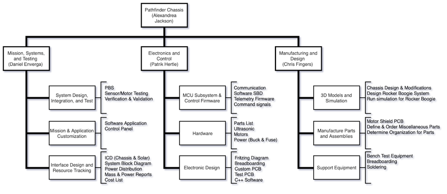
Figure 5: Work Breakdown Structure
The Product Breakdown Structure explains what products each engineer is responsible to complete by the end of the semester.
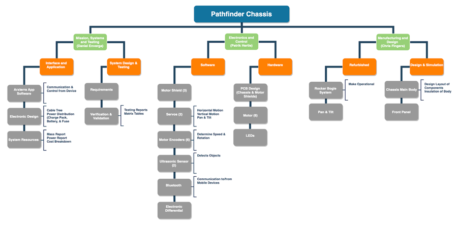
Figure 6: Product Breakdown Structure
Cost
Our budget for this semester was $250 given by Professor Hill. As defined by the cost report we came under the budget by about $7. These items include items purchased only by Pathfinder Generation 7.
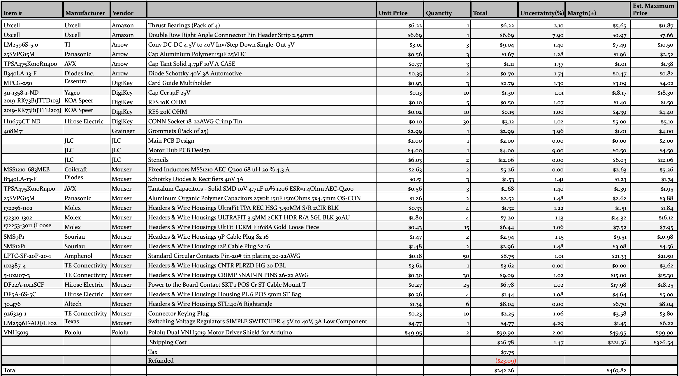
Figure 7: Cost Report
Schedule
For generating the project schedules and Burndown reports, we used Target Process to keep track of times and tasks for the semester. If Target Process is still used in future semesters, be sure to get familiar with it right away and keep it updated as much as possible. This make it easier to generate accurate reports and schedule for the team to follow.
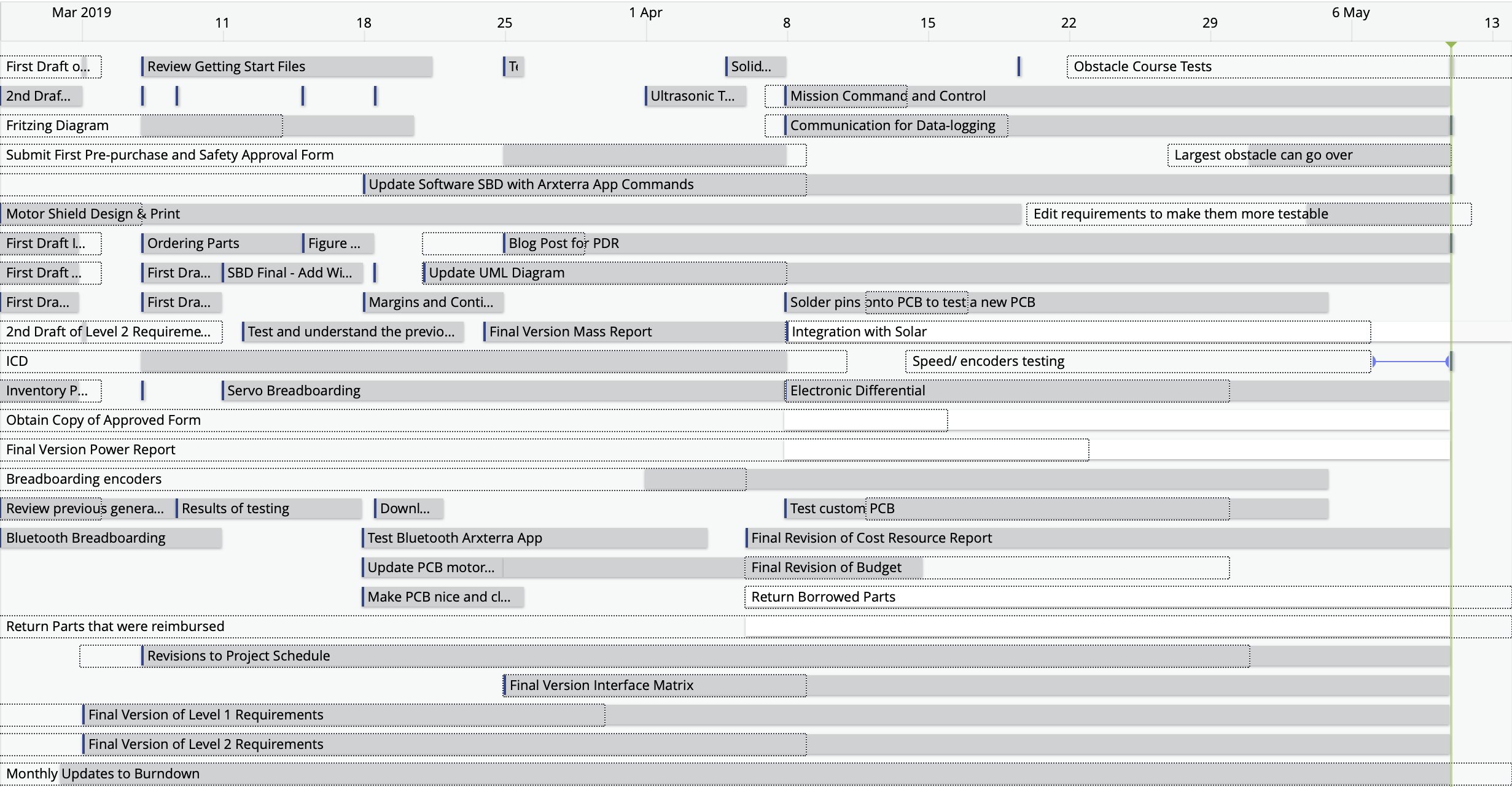
Figure 8: Pathfinder Chassis Project Schedule
Burndown and/or Percent Complete
The project is 89% done with changes and suggestions for next semester. There is always improvements that can be made such as bugs in the code and adjustments to the mechanical design. With only 16 weeks in the semester the tasks completed and overall effort of the Pathfinder Chassis team was a success. Below is the Burndown generated by Target Process.
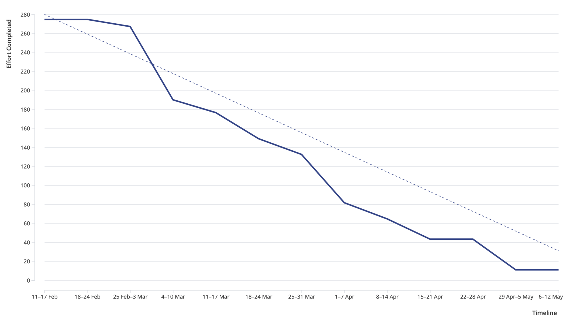
Figure 9: Burndown Generated by Target Process
Literature Review
Understanding the inner workings of the Pololu Dual Motor Drivers was key into adding and including the on board current sensors. Reading through the Pololu Dual VH5019 Motor Driver overview helped give an understanding on to why the current sensors would not be suitable to use. The current sensors located on the motor drivers can accurately read pwm signals of 5khz or higher. This was a problem because the Arduino’s pwm pins frequency, another helpful read is how the Analog Write code operates, up to only 460 hz. A suggestion was to place a capacitor in parallel with the current sensor and ground as to give a better signal reading. This was implemented and works.
A problem our group faced was when two specific motors would shut off when the servos would be connected together. These motors were connected to the digital pins 44 and 45, which operate as pwm pins, however after reading through the different ways each pin acts on the Atmel 2560 datasheet, is shows that these pins can act as timer 5. When the servo.h command is activated, this timer is initialized, which ends up removing the pwm function for pins 44, 45, and 46. These 2 pins were changed and it works fine now.
System Design / Final Design and Results
System Block Diagram
Detailed System Block Diagram(s) of the design. This is an updated and more detailed version of the block diagram presented as part of the conceptual design. Identify connectors, numbers of wires in a bus, and when practical, the names of the wires and buses. As part of your write-up, walk the reader through each subsystem/component block and how they are interconnected (i.e., subsystem and interface descriptions).
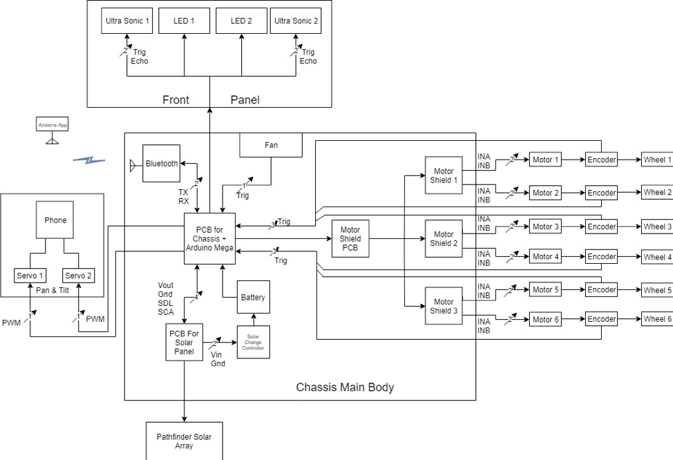
Figure 10: System Block Diagram
Interface Definition
The following is the interface design matrix that was used for the Pathfinder Chassis. The Matrix is color coded to check quickly and effectively which pins affect which part of the Chassis. In this case, all the pinouts for the unused pins are labeled as grey in which can be traced back to the pinout of the Arduino Mega.
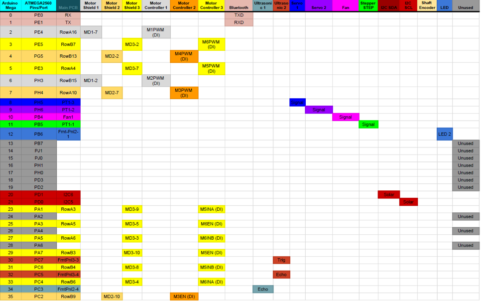
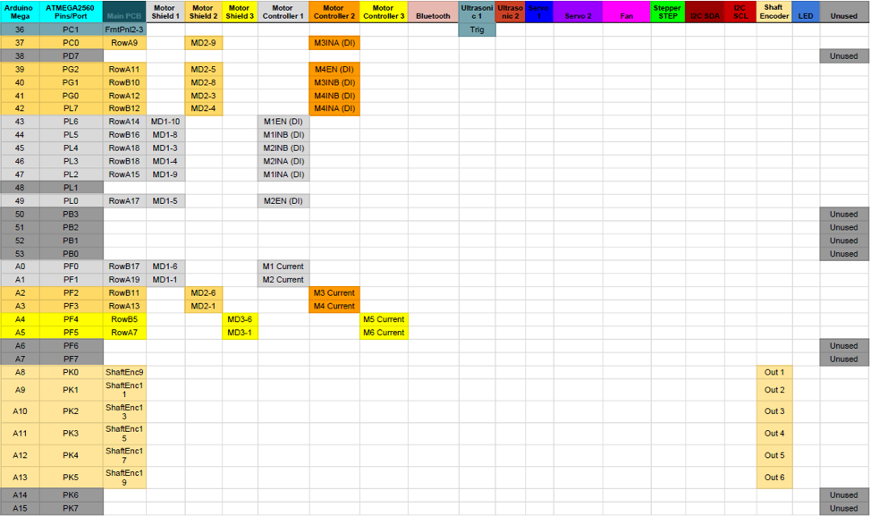
Figure 11: Interface Matrix Design
Interface Control Document
The Pathfinder Chassis Generation 7 will be interfaced with Pathfinder Solar Array Generation 3. The Chassis and Solar Array systems will be interfaced mechanically by the connection of the base plate of the Solar Array system to the top of the Chassis body. The base plate will also function as the top enclosement of the Chassis body. The Chassis will also be able to accomodate the weight of the Solar Array system as the Solar Array will be placed on top of the Chassis. Electronically, the Chassis system will contain the Arduino Mega microcontroller which will allow I2C connections to allow the Solar Array system to transfer its telemetry to the Arxterra Control Panel. The Solar Array system is in charge of charging the lead-acid battery which is powering the entirety of the Chassis system. The use of the CMP12 Solar Charge Controller is necessary to regulate the charge from the Solar Panels to the Battery. The full interface control document can be viewed here.
Mission Command and Control
The following is an image of the Arxterra Control Panel. Some things to note is that the camera is in the vertical position. This is currently because of the orientation of the Pan and Tilt system on the Pathfinder Chassis. Another thing to note is the telemetry, in which we are currently using a single telemetry bar for current sensors and encoders. These telemetry bars represent the average of each of the 6 current sensors and encoders.
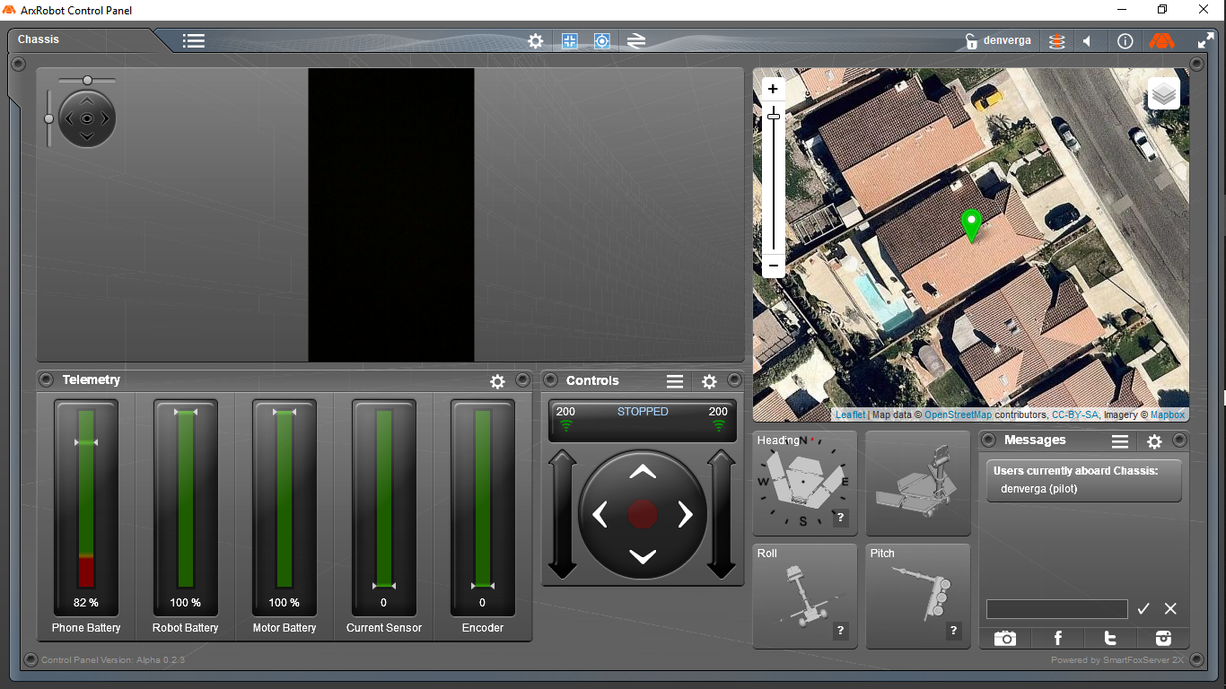
Figure 12: Arxterra Control Panel
Electronic Design
PCB Design
The final PCB design for the Pathfinder utilizes generation 6’s concept in including two seperate PCBs. The design set up for the PCBS is to allow a main pcb that can hold 3 pololu dual motor drivers with plastic cardholders. The motor drivers would then snap into a 2nd pcb that will establish a connection with the main pcb.
MotorHub
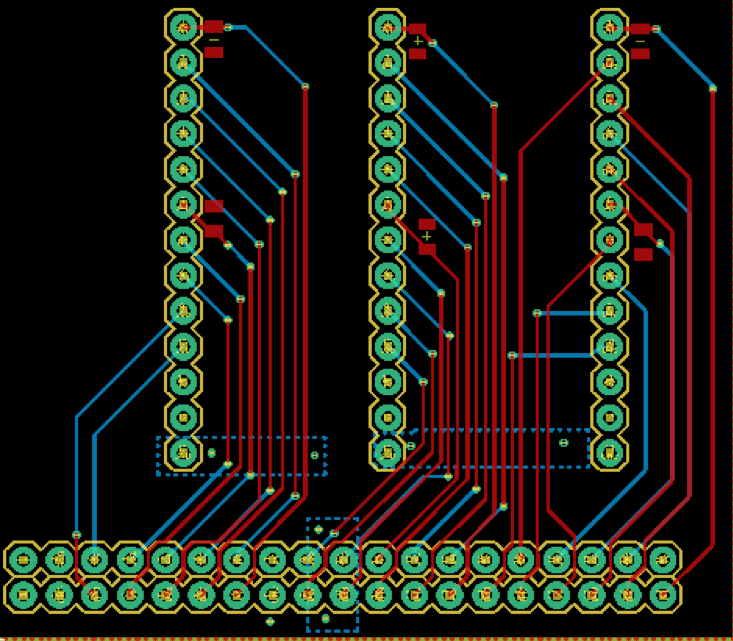
Figure 13: MotorHub PCB Eagle
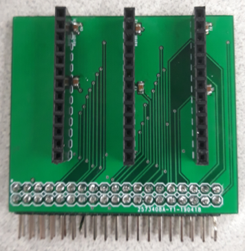
Figure 14: MotorHub PCB
Changes :
- The pins that connected the Pololu Dual Motor Drivers to the Motor Hub have been flipped.
- The original layout had the pins connecting in the wrong way.
- The motor hub’s direct connection pins located on the bottom of the board have been increased to 2×19.
- The Current sensors on the motor drivers as being used.
- Capacitors were connected in parallel with the current sensor pins and ground.
- Polygons were used to allow for optimal ground connection.
- The slots for the Motor Drivers were shifted by 5 mm.
- Male pins connecting from the Motor Hub to the Main PCB are soldered behind the PCB instead of in front of the PCB.
The motor hub, as shown above, connects 3 Pololu dual motor drivers with the M2CS pin on top and the GND pin on the bottom. The bottom 2×19 row of pins are used to directly connect into the main PCB that connects on top of an arduino mega 2560. There is a bottom gnd plane and a top 5V plane that is applied to the layers of the board. Polygon blocks were used to establish a crisper connection between the ground planes. A problem that was discovered while researching the current sensors of the pololu motor drivers is that any pwm frequency that is below 5khz is read incorrectly. By adding a 1 uf capacitor in parallel with each other current sensors, a smoother signal is processed. (Motor Hub Blog Post)
Main PCB

Figure 15: Main PCB
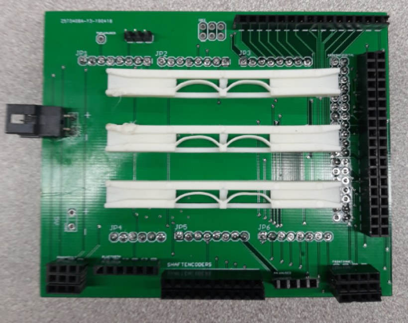
Figure 16: Top Layer of PCB
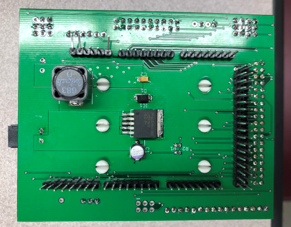
Figure 17: Bottom Layer of PCB
Changes:
- The main PCB has 6 holes that are used for card holders to hold the 3 pololu motor drivers that snap into the motor hub that is connected on the right side.
- Pins on JP4 were shifted to the left by 50 mils, this is to more accurately line up with the Arduino.
- The Pan and tile, ShaftEncoders and the FrontPanel pins were changed from 5 mm pins down to 2.54 mm pins. This is to allow for a motor housing block to be connected with crimped wires. The layout for the LM2596S buck converter was changed and utilizes the online datasheet to design the optimal connections for the buck.
- In the polygons for the buck converter layout, multiple vias were placed as to allow a better connection with the 5 volt layer and the 5 volt output of the buck converter.
- The battery and 5 volt input/output connections were changed from 5 mm down to 3.5 mm power inputs.
- Resistors R1 and R2 were switched around and increased by a factor of 10.
- The Motor Driver pin connections on the right were increased to 2×19, this is because this iteration of the board uses the current sensors on the motor drivers and not separate ones.
- On that note, the 6 current sensors that were originally used have been removed.
- Unused pins were allocated to different sections of the board.
- Motor driver pins 44 and 45 were shift to pins 5 and 6.
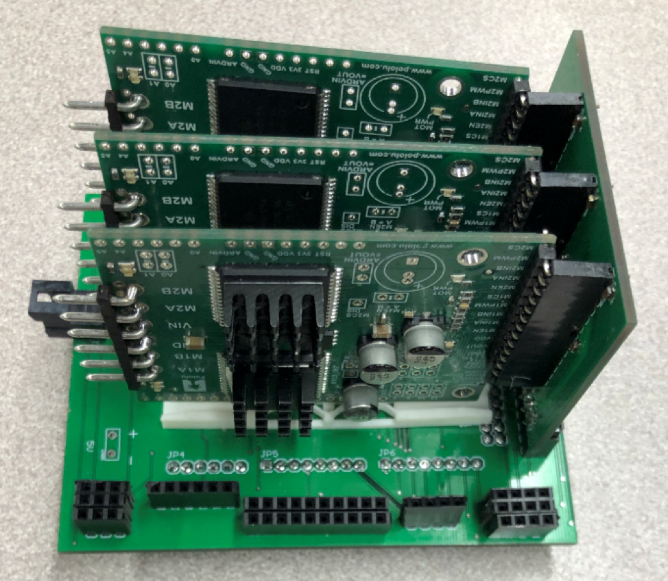
Figure 18: Full Assembly of PCB
The main PCB is what sets all of the connections between the motor hubs, pan and tilt, bluetooth, fan, front panel, I2C, and the ShaftEncoders. The layout of the PCB is taken from generation 6’s design, but with needed improvements. The Arduino can handle up to 12V supplied directly to it, however problems can start arising with extended usage. A LM2596S buck converter is used to circumvent this problem. The buck converter steps down the input voltage to a more manageable 5 volts that then supplies the rest of the arduino. The layout for the buck converter was taken from the ideal layout listed on their datasheet, with the capacitors, diodes and inductor values found out by using Texas Instruments online custom circuit design tool. Instead of using direct line connections for this layout, polygon blocks were used as per the online data sheet. The wired connection between the bluetooth and the arduino’s rx to tx pins required a voltage divider to make sure the correct amount of voltage, 3.3V, was being supplied to the wireless device. Using voltage divider, a 20k ohm resistor and a 10k ohm resistor were used to step down the voltage to 3.3V. The ohm resistance was chosen as to allow for less power loss. Originally generation 6 used current sensors that attached directly to the main PCB because of their load test, however with the addition of a 1 uf capacitor connected parallel to each of the current sensors on the motorhub this problem can be avoided. All of the current sensors that were originally on the main pcb have been removed. The card holders for the dual motor drivers are placed in a way to allow for the Motor Drivers to snap into the motorhub PCB and moved back by 1 mm. Unused pins have been designated all around the pcb for future use and testing. There was a problem that we encountered while testing the motors when a servo was installed. Two of the motors, whose PWM pin was set to the Arduino’s pin 44 and 45, would lock up. When the servo.h command is included in Timer 5 is activated to control how the servo will function, however pins 44, 45, and 46 are tied to this timer. When this happens the pins lose their PWM function ability and can only be used as digital input pins.
Firmware
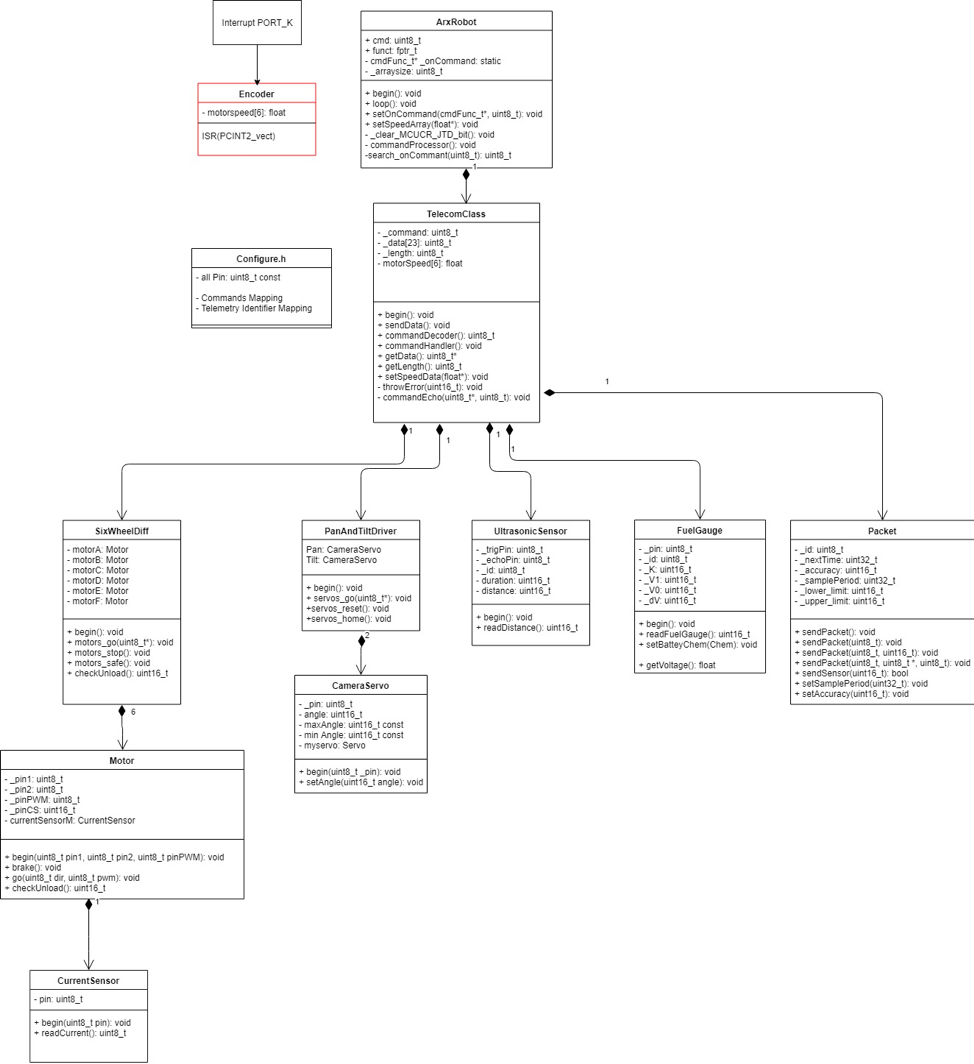
Figure 19: UML Diagram
The UML diagram is a way of clearly displaying the software design. All classes are displayed graphically and also show the order of rank among each other. To get an overview of all classes I start with the top class TelecomClass, because the ArxRobot class already existed and only serves to execute the TelecomClass.
Two methods are essential in TelecomClass. On the one hand the CommandHandler() method which is there to control the motors, servos and LEDs. On the other hand the method SendData() for Telemetry Datas is important to update all sensors. Let’s start with the command functions first.
Commands:
The MOVE Command controls the motors. This contains the speed and direction for the left and right side. The data bytes for this are sent to the 6-wheel differential, which has 6 motors as objects and controls them as in the blog post 6-wheel differential.
The CAMERA_MOVE command contains two angles (for pan and tilt), which are normally uint16_t, but are sent as two byte arrays. First the angle is sent as an array to the object PanAndTiltDriver, which has two servos as objects. Before the PanAndTiltDriver class passes the angle on to the servos, it converts the two byte array into a uint16_t. The Servo Object uses the Arduino Library Servo.h to run the Servos.
HEADLIGHTS_ON and HEADLIGHTS_OFF is not yet implemented.
Telemetry:
First, the objects for the individual sensors are created in TelecomClass. These include methods that allow you to read the required data.
For example, two ultrasonic sensors of the Ultrasonic Sensors class are created which pass the measured distance with the readDistance() method. The function used for this was taken from a code example and is self-explanatory.
The same principle applies to the Current Sensors, which are not created in the TelecomClass, but are each created by a motor object. For the calculation of the current the conversion used from the Pololu Motordriver Arduino Code Example was used. This data is then forwarded via the transferred classes to the TelecomClass.
The encoders are a special case for determining measurement data. For this the analog pins of port K had to be reprogrammed first as PC_INT, which then trigger an interrupt (PCINT2_vect) by a HIGH level. This is done by measuring the time difference between the last and current interrupt. In the loop() of the . ino code a RPM speed is calculated and forwarded to the Telemetry Class.
Now we have all sensor measurement data in the TelemetryClass. These will now be sent to the ControlPanel as explained in Custom Telemetry Blogpost.
Notice:
The method for measuring the Current Sensor is in each motor object. This has the background that the calculation of the unloaded case should take place here. Only a check must take place which releases the motors or not. Since the method checkUnload() in the current sensor class is already permanently updated for each sensor. This means that everything is already available, only a calculation has to be implemented and tested in this method.
Furthermore, no speed controller has been developed yet. It would make sense to pass on the measured speed to the motor objects and control the set speed by a PID controller.
Mechanical/Hardware Design
The Solidworks model for the Pathfinder utilizes previous generation parts in terms of the main body, wheels, legs, and Pan and tilt. The main change for the model is the inclusion of the pan and tilt on the most recent model and the change to the pcb located inside the body of the bot.
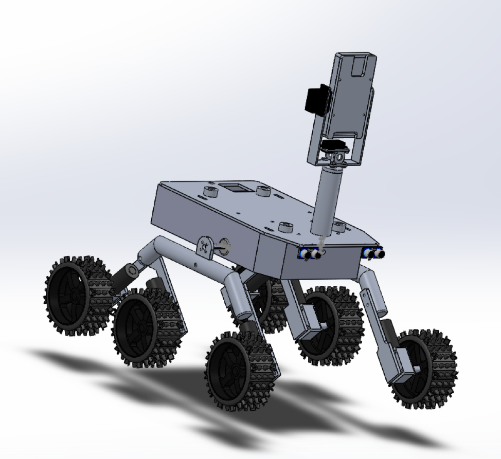
Figure 20: Fully Assembled Chassis Body
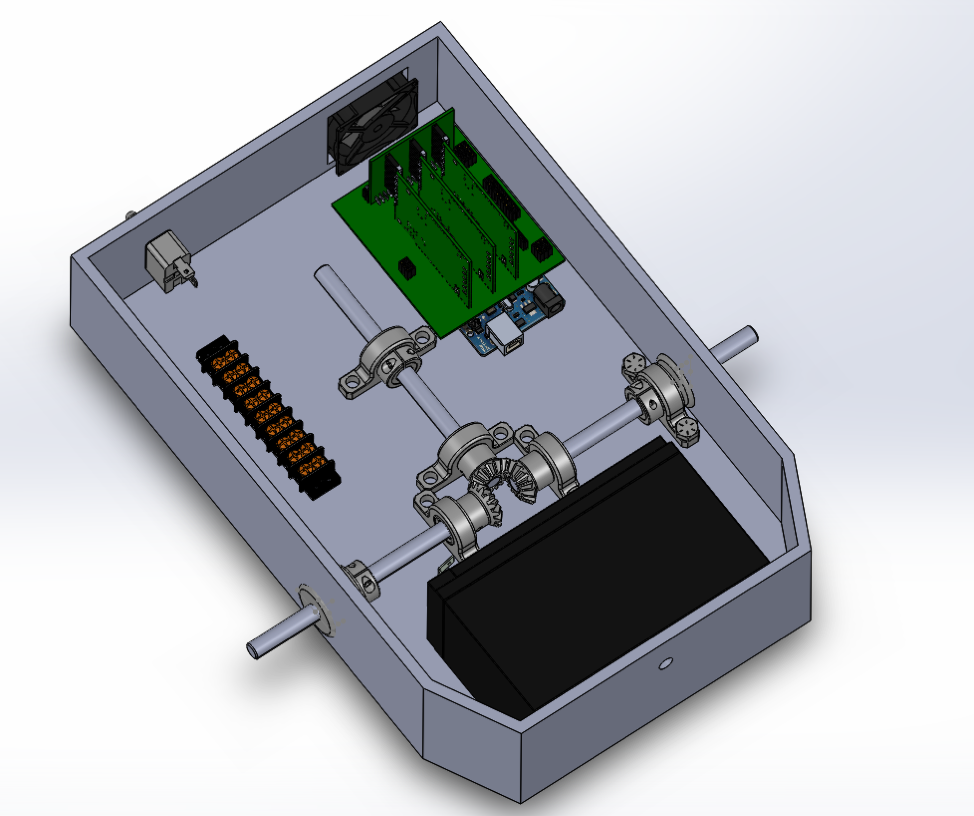
Figure 21: Chassis Body
The updated PCB design was put into the Solidworks model for the Chassis.
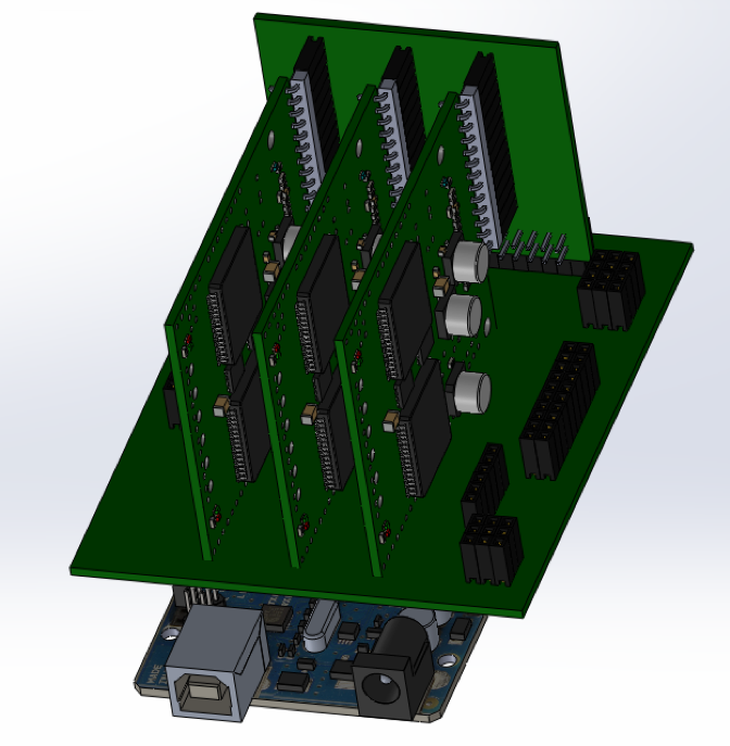
Figure 22: SolidWorks Design for PCB connection
Pathfinder generation 7 used the exact same chassis, legs, and wheels as from previous semesters, however some things were added and removed.
Grommets:
Installed to prevent dust damage from entering the side port area where the differential gear box connects with the main wheels. These grommets are .375 in bore dimension, 1 inch for the inner diameter, 1 ¼ inch for the outside dimension and ⅛ inch in thickness. With the differential bar not being completely centered with the cut out hole, the grommets had to be inserted forcefully.
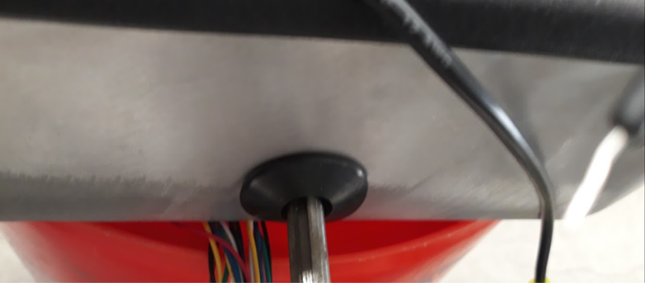
Figure 23: Installed Grommet
Thrust Ball Bearings:
Previous semesters utilized standard one direction bearings that acted simply as washers. With thrust ball bearings, functionability is taken into account for the rotation will be allowed two ways. The bore diameter is 10 mm, outer diameter is 26 mm.
Mechanical Stop:
Rubber stoppers were installed on the front and side of each other metal pipes that are near the rocker portion of the rocker bogie system. This is too make it so the rocker does not end up flipping the wheels when it hits a wall it cannot traverse over. The idea to use plastic stoppers instead of a metal bar is to prevent metal on metal contact.
There was a metal stop that was installed underneath the Pathfinder, however this ended up being removed. The metal stop was not able to perform as intended.
Verification & Validation Test Plan
The verification test plan is based on the requirements derived from the mission profile created at the beginning of the semester. Below is the verification test plan matrix. For more step by step cases and linkages to the requirements, go to the verification test plan blog post.
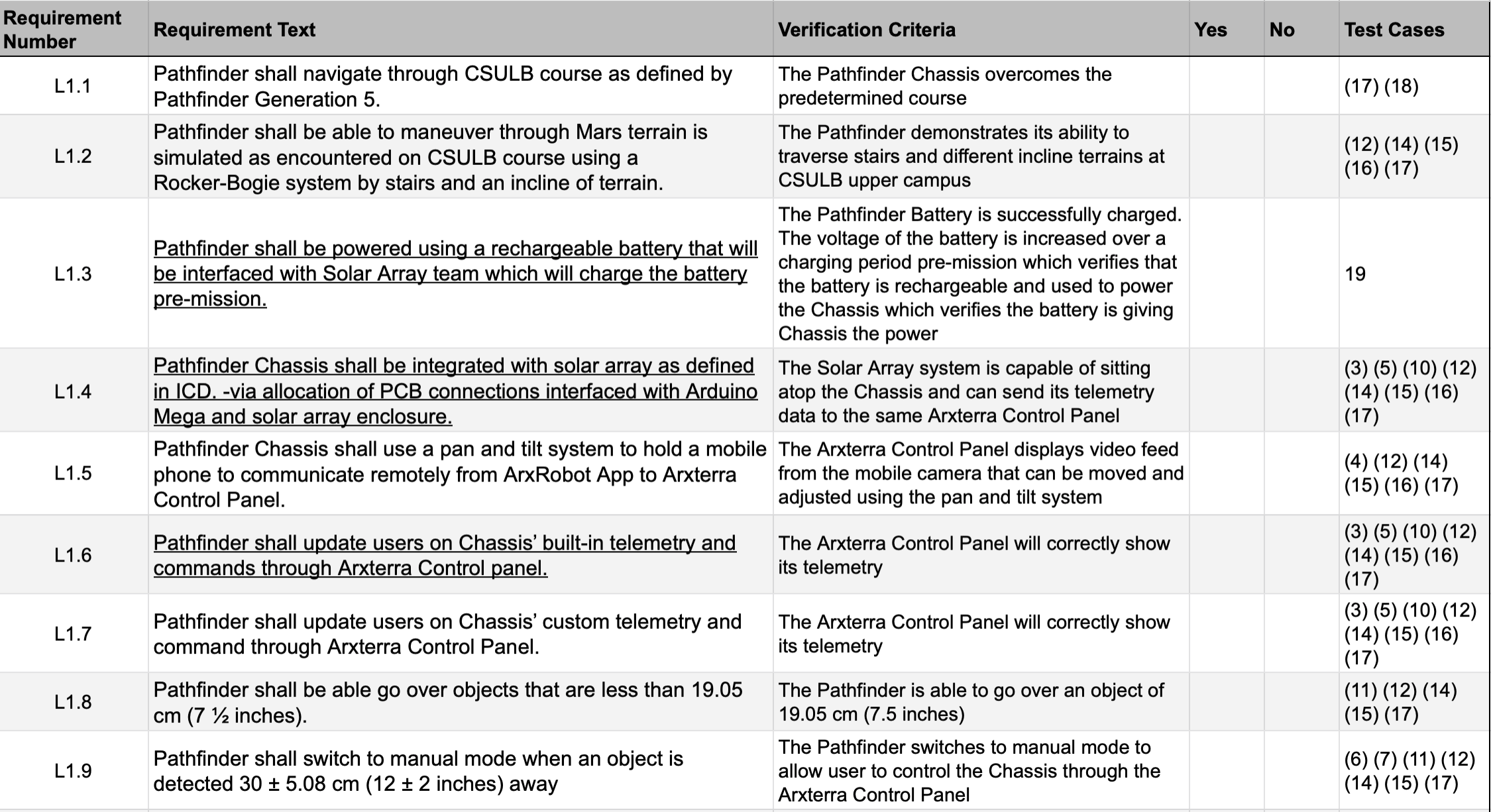
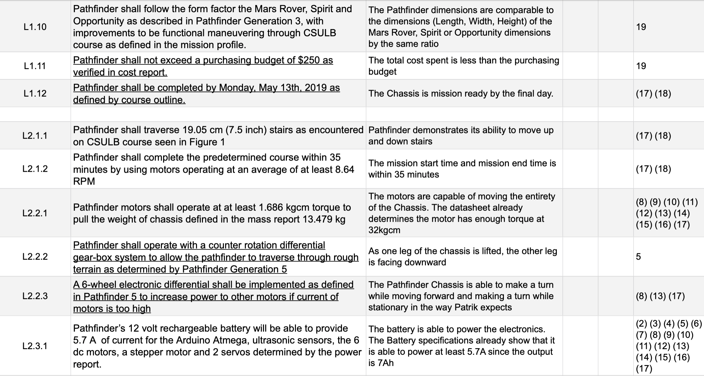
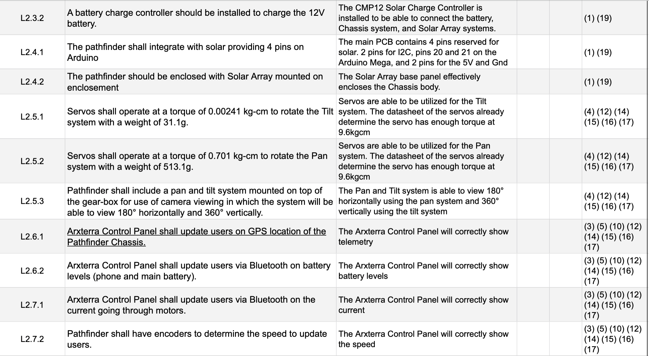
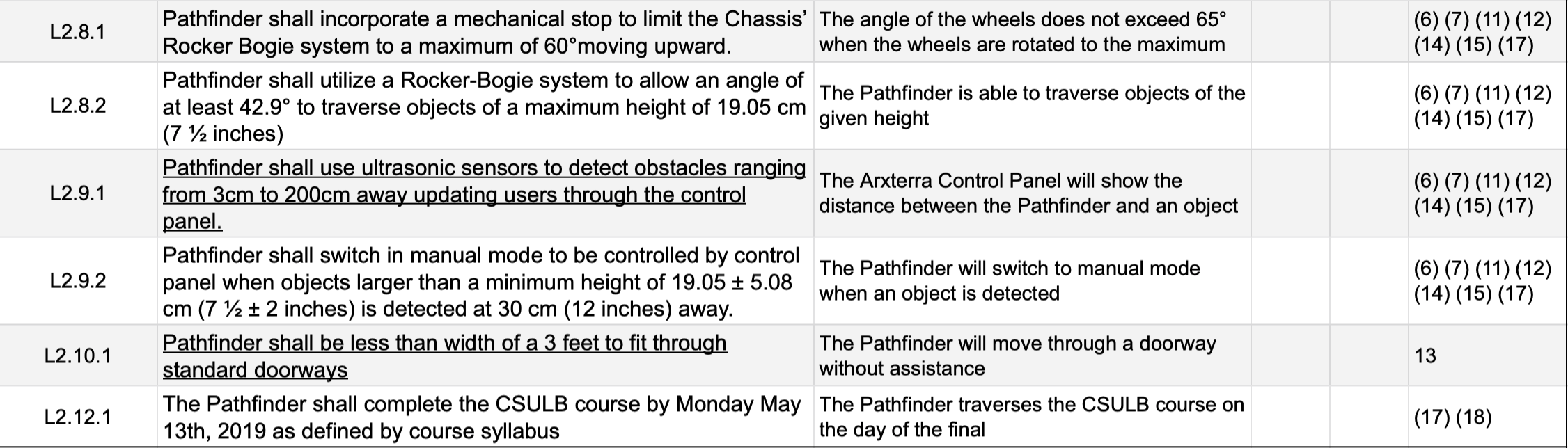
Figure 24: Verification Testing Plan
Concluding Thoughts and Future Work
There are several changes and improvements that can be implemented in future generations. For one, the PCB can be designed to incorporate Arduino Mega ADK, add capacitors for Pan & Tilt, shift pins for motor drivers down to put use for cardholders, and switching some of the pin rows to switch connector type. This year we had a solid firmware update that would be a great basis and start for future generations. There are several updates such as waypoint, automatic turning when object is detected, PID controller, etc. Lastly, as for mechanical design, a spring loaded front wheel driver would be useful to add to the rocker bogie system and improving the current mechanical stop by 3D printing or other methods. Another improvement and suggestion would to be make sure the rocker bogie system is designed correctly to traverse through the stairs that are defined in the obstacle course.