Polyfuse Testing and Implementation
By Kevin Huynh, Project Manager / Computer Systems and Software
Objective:
The first test will verify whether or not the servos used will be protected from drawing too much current when they stall. The current level that will be considered dangerous for the Power HD 1501MG servo is the stall current listed in the datasheet (2.3 A at 4.8 V). The second test will check how long it takes for the polyfuse to trip at its rated trip current and how much leakage current there is.
Test Materials:
1. Arduino MEGA 2560
2. Power HD 1501MG
3. 06R120BU Littelfuse Polyfuse
4. UBEC-5A-HV DC-DC regulator
5. Extech EX330 Digital Multimeter
6. 7.5 V 2.4 A Wall Power Supply
7. DC Bench Power Supply
8. Pliers
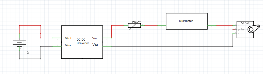
First Test Setup:
First Test Procedure:
1. Set the circuit up as shown in the setup section. First without the polyfuse.
2. Choose a servo horn to place on the servo, the servo horn used for this test was the four point star.
3. Keep the servo from rotating the horn using the pliers.
4. Use either an Arduino program or the Robot Poser program (Biped) to control the servo. If using an Arduino program, have the servo continuously rotate between two points.
Sample code for rotating a servo can be found here: http://arduino.cc/en/Tutorial/sweep
If using the Robot Poser program, use the sliders to change the servo angle.
5. Record the current measured on the multimeter, then repeat with the polyfuse in place.
First Test Results:
Before connecting the polyfuse in between the UBEC and the servo, the highest current was approximately 2.25 A for a brief moment, then consistently about 1.8 A in later tests. While the stall current is not at the level specified in the datasheet for the Power HD 1501MG, the temperature seemed to increase slightly.
With the polyfuse, the highest current value achieved during the test was approximately 1.1 A, which is very close to the rated holding current of the polyfuse. Since 1.1 A is well below the stalling current found in the previous test and the datasheet, the current is at a relatively safe level. What was unexpected was that the polyfuse acted similarly to a constant current limiter, with the hold current being the limit.
Second Test Setup:

Second Test Procedure:
1. Set the circuit up as shown in the setup section.
2. Set the voltage level of the power supply to the output voltage of your regulator (if applicable).
3. Increase the current to the rated trip current of the polyfuse and record the time it takes for the polyfuse to trip.
Second Test Results:
There were two tests conducted because of the results found in the first test. One test was used to find the trip time of the polyfuse at 2 A, the other was used to find the trip time of the polyfuse at 1.8 A. The trip time at 2 A, the rated trip current of the polyfuse, was approximately 7 seconds and the trip time at 1.8 A, the stall current of the servo, was approximately 12 seconds. The leakage current was around 0.09 A, which is far below the rated no load current and is unlikely to damage to the servo.
Conclusion:
Now that the polyfuse is confirmed to trip at both its rated trip current as well as slightly below the rated trip current, the polyfuses can be implemented into the robots. Although the trip times were somewhat slow, the polyfuses’ behavior as a current limiter at a current level slightly below the hold current (1.2 A) seems to avoid the need to trip at all.
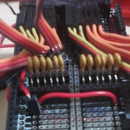
Implementation (See the following picture for the schematic):
https://www.arxterra.com/wp-content/uploads/2014/04/servoProtection.jpg
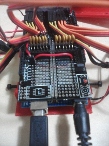
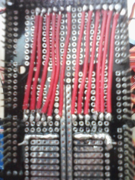
By soldering female headers into the protoshield and the inserting the polyfuses into those headers, the drawback of having to replace them after they trip is simplified. The polyfuse leads seemed to be a bit thin, so tape is recommended to help keep the polyfuses from falling out of the headers.
Test Videos Playlist:
Test Video