Table of Contents
Engineering Design
Engineering design is a process of devising a system, component, or process to meet desired needs and specifications within constraints. It is an iterative, creative, decision-making process in which the basic sciences, mathematics, and engineering sciences are applied to convert resources into solutions. Engineering design involves identifying opportunities, developing requirements, performing analysis and synthesis, generating multiple solutions, evaluating solutions against requirements, considering risks, and making trade- offs, for the purpose of obtaining a high-quality solution under the given circumstances. For illustrative purposes only, examples of possible constraints include accessibility, aesthetics, codes, constructability, cost, ergonomics, extensibility, functionality, interoperability, legal considerations, maintainability, manufacturability, marketability, policy, regulations, schedule, standards, sustainability, or usability.
– ABET Glossary F’18
Terminology
Constraint
A constraint is a condition that must be met. Sometimes a constraint is dictated by external factors such as orbital mechanics (schedule) or the state of technology; sometimes constraints are the result of the overall budget environment. It is important to document the constraints and assumptions along with the mission objectives. [1]
In this definition we see a clear delineation between constraints (cost and schedule) and performance (mission objectives). [3]
Constraints may also take the form of compliance with standards, codes, and technical regulations. These evolve from the concept of interoperability.
Interoperability
Interoperability is a characteristic of a product or system, whose interfaces are completely understood, to work with other products or systems, present or future, in either implementation or access, without any restrictions. [4]
Within the context of the course we will limit the scope of interoperability to its original definition; in other words, information technology and systems engineering applications. A broader definition takes into account social, political, and organizational factors that impact system to system performance.
In the Figure 1 we see the term “interoperability” within the context of “compatibility” and “de facto standard. Historically, interoperability is the codification of a de facto standard by a recognized professional organization, like the IEEE .

Figure 1. Interoperability
With respect to the Open Systems Interconnection model (OSI model) [5], interoperability may be present at each layer. Examples at higher layers include XML and SQL. At lower layers we have ASCII and Unicode. At the hardware (physical) layer we have serial communication protocols like the I2C serial peripheral interface (SPI), universal asynchronous receiver-transmitter (UART); all supported by the 3DoT board.
Standards
Standards provide a proven basis for establishing common technical requirements across a program or project to avoid incompatibilities [2] and may in some instances actually lower implementation cost.
This most common example of standards is in weights, measures, and monetary.
Codes
Laws that specify minimum standards to protect public safety and health such as codes for construction of buildings. Initially voluntary and consensus standards, later incorporated into codes. Codes which apply to product development and workmanship are included in the product specifications.
Technical Regulation
A technical regulation is a Government document that defines product characteristics or their related processes and production methods, including the applicable administrative provisions, with which compliance is mandatory. [7]
The difference between standards, codes, and technical regulations lies in compliance. While compliance with standards is voluntary, codes and technical regulations are by nature mandatory.
Organizations that Define Standards, Codes, and Regulations
Standards Organizations
Following is a small representative sample of organizations that establish standards.
- ASTM (American Society for Testing and Materials)
- IEEE (Institute of Electrical and Electronics Engineers)
- ASME (The American Society of Mechanical Engineers)
- ANSI (American National Standards Institute)
- NASA Standards
- ISO (International Organization for Standardization)
Codes and Regulatory Organizations
Here are two examples of organizations that establish codes and regulations.
- United States Department of Justice Civil Rights Division, Americans with Disability Act (ADA)
- In Canada, national construction codes are published by the National Research Council of Canada.
References/Resources
Program Constraints
From Constraints to Programmatic Requirements
A critical part of the design process is an early understanding of the overall real-world constraints placed on the program. These constraints may come from the customer “programmatic” or the implementing organization “institutional.” The specific constraints applied to the program are a subset of the constraints, standards, codes, and regulations under which the customer or implementing organization operate. These constraints are typically not able to be changed based on trade off analyses. Once this subset is defined, they become programmatic requirements. Once these constraints are defined requirements can be further defined by establishing performance criteria. The performance is expressed as the quantitative part of the requirement to indicate how well each product function is expected to be accomplished. The rationale should be kept up to date. Often the reason for the requirement is not obvious, and it may be lost if not recorded as the requirement is being documented. The reason may point to a constraint or concept.
This flow-down of customer and institutional constraints into requirements is illustrated in Figure 2.
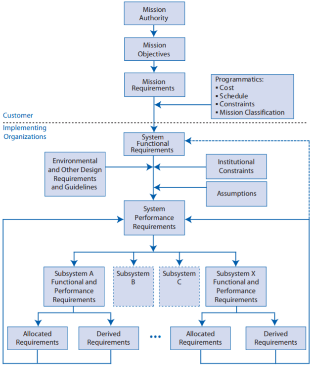
Figure 2. The flow-down of constraints into requirements
As part of your final report you will need to review and show compliance with constraints on the project imposed by The Robot Company (i.e., CSULB) and Project Stakeholders.
Project/Economic
Subcategories: Cost, Extensibility, Interoperability, Maintainability, Quality, Marketability, and Schedule
All 3DoT robots shall be constrained to a a Cost not to exceed $250.
All project Schedules shall be constrained to a completion date of Tuesday December 18, 2018. Project completion includes documentation and materials purchased by or loaned to the project.
One of the Economic Factors affecting our robots are return rates. To demonstrate the durability and child friendliness of our robot a simple drop test from 1.4 meter shall be performed. The height is defined by the average height of an average 11 year old girl.
Extensibility is designed into the 3DoT board by way of one 8-pin 100 mil connector located on the front of the board and two 8-pin 100 mil connectors located on the top of the board. By plugging shields into these connectors, the 3DoT board can support a diverse set of robots. All robots shall contain one or more custom designed 3DoT shields. The 3DoT shield(s) incorporating interface electronics between the 3DoT board and sensors and/or actuators unique to the robot. Surface Mount Technology (SMT) will be employed unless a waiver for through-hole parts is granted.
Maintainability: Disassemble and Reassemble of the robot shall be constrained to less than 20 minutes (10 + 10 minutes). Disassembly: The 3Dot board is clear of all other electronic and mechanical subassemblies. All electronic and mechanical subassemblies and associated connectors, sensors, and actuators including motors are disconnected. A functional test of the robot is conducted after reassembly to confirm its functionality. All project may reference a cable tree as well as an assembly diagram as necessary. This requirement is demonstrated/verified on the last day of the schedule. Projects may request a waiver with justification.
Social and Ethical
Subcategories: Accessibility, Aesthetics, and Usability
Accessibility by the blind and Marketability of the robots shall be implemented/enhanced by a speaker. The speaker shall generate sound effect consistent with the type of the robot. For example, the Goliath tank would make “track” sounds, the AT-ST sound effects would mimic their Star Wars antecedent.
To enhance Aesthetics, the robot shall be designed in such a way that there are no dangling or exposed wires. Compliance with this requirement, includes the use of keyed and clearly labeled connectors between all electronic and electromechanical components. Do not use jumper wires; ribbon cables are preferred but not required. Loose wires should be contained using spaghetti tubing (not shrink tubing). For 3DoT projects consider using terminal blocks, 100 mil contact pins and headers, 2.0mm PH series JST connectors, and barrel connectors. Handling Precaution for Terminal and Connector will be in compliance with JST documentation.
To enhance Aesthetics, the form factor of a robot modeled on a real or fictitious robot shall be constrained by the original. For example, Goliath should be a scale model of the real Goliath 302 tank. Projects may request a waiver with justification.
Usability of the robots shall be enhanced by adding autonomous functions and/or by use of the Arxterra phone and control panel application as dictated by the assigned mission.
Manufacturability
Subcategories: Constructability, Size, Weight, and Power (SWAP)
Constructability of 3DoT robots shall be documented at the CDR and approved by the president of the TRC robot company. Constraints imposed by this requirement include the use of bushing or bearings in all moving and rotating parts. Interlocking Hinges with latching mechanism. No gaps greater than 1 millimeter, and immediate access to all external connectors (USB, switches).
Manufacturability of 3D printed robots shall be demonstrated by compliance with the 3/3/3 rule. Specifically, total print of a robot is constrained to 9 hours, with no single print taking longer than 3 hours. Projects may request a waiver with justification. This requirement is waived for 3D prints provided by the library’s Innovation Space. In its place, all 3D prints provided by the library’s Innovation Space should minimize the number of files to be printed. Justification should be provided if more than one (1) file is required.
The Size of the electronics enclosure, shall be constrained to be no greater than the 3DoT board, 3DoT shield(s), and associated mounting hardware.
Power to all 3D robots shall be provided by the 3.7V RCR123A battery included with the 3DoT board or use of the external battery 2.0mm PH series JST connector located on the 3DoT board. The RCR123A is a Lithium Polymer LiPo battery. All Safety regulations as defined in Section 4.3 Hazards and Failure Analysis of this document shall apply to the shipping, handling, storage, and disposal of LiPo batteries.
Power to all 3DoT robots shall be provided by the 3.7V 750 mA 2.775Wh Li-Ion battery included with the 3DoT board or use of the external battery 2.0mm PH series JST connector located on the 3DoT board. Compliance will be provided in Section 3.5 Power in the Final Blog Post. Measured current shall have a margin of 5%. Contingency shall be based on measured current, plus margins associated with each line item, minus 750 mA with an assumed depth of discharge of 80% grams (i.e., 600 mA).
Back of the envelope calculations and experiments shall be conducted to set the diameter of Power carrying wires. Follow the American Wire Gauge (AWG) standard when defining the diameter of power-carrying wires. This work to be completed and documented by the CDR.
Environmental Health and Safety (EH&S) Standards
Subcategories: Environmental Standards, Sustainability, Toxic waste (Solar panels), Health and Safety, Ergonomics
All standards, codes, and regulations as defined in the “Engineering Standards and Constraints” Section of this document shall apply.
All Lithium (Li-ion, Li-polymer) batteries shall be purchased with and stored, when not in use, in a fire and explosion proof battery bag.
Robot Interoperabilty
All 3DoT robots shall incorporate the 3DoT v9.05 or later series of boards.
Software shall be written in the Arduino De facto Standard scripting language and/or using the GCC C++ programming language, which is implements the ISO C++ standard (ISO/IEC 14882:1998) published in 1998, and the 2011 and 2014 revisions. Required exceptions to this standard can be found here.
All 3DoT robots shall be in compliance with the 3DoT Command and Telemetry Packet specification.
All 3DoT robots shall be controlled via Bluetooth 4.0 in compliance with the Bluetooth Special Interest Group (SIG) Standard (supersedes IEEE 802.15.1).
Allocated Requirements / System Resource Reports
Allocated requirements, also known as resource reports, are written and tracked by the System Engineer. The types of resource reports are based on the project. For example, power allocation/estimate for each subsystem module of a spacecraft would be important, while a more loose tracking for a toaster would be in order. Each resource should have a margin attached to it based on the uncertainty in the estimate. It should also show contingency, where contingency is defined as the project allocation minus the estimate plus total margin. Project allocations shall be based on a model (back-of-the-envelope, simulation, prototype, etc.) or other rationality (e.g., similarity to a related product).
Section shows updated useable capacity of the power source selected for the project. Typically represented in a tabulated format, it should include an expected current drawn, measured current drawn, percent uncertainty, and margin for each resource consuming power. Lastly, it should contain total expected current, total margins, project allocation, and contingency clearly showing the power source selected will support the project.
This section is comparable to the previous power allocation section however, dedicated to the updated mass of the project. Also in a tabulated format, it should contain the expected weight, measured weight, percent uncertainty, and margin for each respective resource being used in the project. Lastly, it should contain total expected weight, total margins, project allocation, and contingency.
Any other resources tracked by the system engineer. For example, 3DoT projects using a 3D printer have an 9 hr. (3/3/3) resource requirement that must be tracked.
Cost
This section should contain an updated table listing all of items purchased for the project including prototype cost, parts and implementation, PCB manufacturing cost etc. Like all allocated resources (see Mass and Power), this chart should contain the expected cost, actual cost, percent uncertainty, and margin for each item listed in the table. Lastly, it should show the total expected/final cost, total margins, project allocation, and contingency.
Schedule
This section should contain an updated schedule, generated through programs like ProjectLibre or Microsoft Project, showing the system and subsystem tasks that have been completed or are still in progress. It is important to include the project’s critical path (visually representing the critical path in the schedule diagram is recommended).
Interface Definition
This section is an updated version of the Interface Matrix presented at the PDR and CDR. An additional section should discuss the Cable Tree (i.e. wire harness, wiring diagram, etc.) developed in concert with the E&C and MFG showing how the wires, cables, and connectors were integrated into the final product.
If your project has includes and Interface Control Document (ICD), it would go here: top level explanation of MST communication, E&C connections, MFG mating and fastening → to be covered in detail later in the presentation during respective sections.
Verification & Validation Test Plan
Once an acceptable design solution has been selected from among the various alternative designs and documented in a technical data package, the design solution must next be verified against the system requirements and constraints.
The verification must show that the design solution definition:
- Is realizable within the constraints imposed on the technical effort;
- Has specified requirements that are stated in acceptable statements and have bidirectional traceability with the derived technical requirements, technical requirements, and stakeholder expectations; and
- Has decisions and assumptions made in forming the solution consistent with its set of derived technical requirements, separately allocated technical requirements, and identified system product and service constraints.
Additional Reading and Resources:
- Arxterra / Getting Started / Systems Engineering / Missions, Systems and Test Timeline
- Week #7 – Product Verification & Firmware Setup
- Week #8 – Product Validation & Cable Tree/Cable Routing Diagram
- Sample Verification and Validation Plans
In your final report begin by presenting your strategy for verifying that your design meets design requirements and how you will validate (i.e., the mission plan) that you built the right product for the mission. The next section should present your project’s verification test plan as an overview/summary level. The Verification and Validation Test Plan should be uploaded to BeachBoard and provided in printed form at the day of the mission.
Engineering Standards, Codes, and Regulations
Standards provide a proven basis for establishing common technical requirements across a program or project to avoid incompatibilities and ensure that at least minimum requirements are met. [2]
The most common example of standards is in weights, measures, and monetary.
Standards provide a proven basis for establishing common technical requirements across a program or project to avoid incompatibilities and ensure that at least minimum requirements are met.
Standards in common use, such as weights and measures, can result in lower implementation cost as well as costs for inspection, common supplies, etc. Typically, standards (and specifications) are used throughout the product life cycle to establish design requirements and margins, materials and process specifications, test methods, and interface specifications.
Standards are used as requirements (and guidelines) for design, fabrication, verification, validation, acceptance, operations, and maintenance.
Standards are generated from many sources, leading to confusion, contradiction, and a need for prioritization. Here is one way standards may be prioritized.
- Standards mandated by law (e.g., environmental standards)
- National or international voluntary consensus standards recognized by industry,
- Government standards
- Customer and Institutional policy directives, and technical standards.
Depending on the specific domain or discipline, there may be industry and Center-specific standards that must be followed, particularly when designing hardware. This can be evident in the design of a mechanical part, where a mechanical computer-aided design package selected to model the parts must have the capability to meet specific standards, such as model accuracy, dimensioning and tolerancing, the ability to create different geometries, and the capability to produce annotations describing how to build and inspect the part. However, these same issues must be considered regardless of the product. [3]
To learn more about standards read NASA System Engineering Handbook, Sections 4.2.2.5 Technical Standards and 7.3.4 Design Standards, of which the above is an abridged version.
Program Standards, Codes, and Regulations
As part of your final report you will need to review and show compliance with standards, codes, and regulations adopted by The Robot Company (i.e., CSULB) and Project Stakeholders. Specifically include University and applicable environmental, health, and safety standards and those safety standards specifically associated with the product (e.g., Children’s Toys).
Applicable Engineering Standards, Codes, and Regulations
- IEEE 29148-2018 – ISO/IEC/IEEE Approved Draft International Standard – Systems and Software Engineering — Life Cycle Processes –Requirements Engineering.
- NASA/SP-2007-6105 Rev1 – Systems Engineering Handbook
- Bluetooth Special Interest Group (SIG) Standard (supersedes IEEE 802.15.1)
- C++ standard (ISO/IEC 14882:1998)
- Federal Communications Commission (FCC) Relevant standards for a product implementing a 2.4GHz radio, FCC Intentional Radiators (Radio) Part 15C, and Unintentional Radiators FCC Part 15B for CPU, memories etc.
- NXP Semiconductor, UM10204, I2C-bus specification and user manual.
- ATmega16U4/ATmega32U4, 8-bit Microcontroller with 16/32K bytes of ISP Flash and USB Controller datasheet section datasheet, Section 18, USART.
- USB 2.0 Specification released on April 27, 2000, usb_20_20180904.zip
- Motorola’s SPI Block Guide V03.06
Environmental, Health, and Safety (EH&S) Standards, Codes, and Regulations
CSULB College of Engineering (COE) Safety Resources. Start your search for applicable CSULB COE Safety Standards and Procedures here. Please review and acknowledge if any safety issues as defined by the COE applicable to your project. For example, the closest safety constraint for a linear actuator is for use of the Hydraulic Press located in the Engineering Technology (ET) Building Lab. Here is a link to the Hydraulic Press Safety document.
CSULB Environmental Health & Safety (EH&S)
IEEE National Electrical Safety Code (NESC)
NCEES Fundamental Handbook (FE) Reference Handbook
ASTM F963-17, The Standard Consumer Safety Specification for Toy Safety, is a comprehensive standard addressing numerous hazards that have been identified with toys. In 2008, the Consumer Product Safety Improvement Act of 2008 (CPSIA) mandated that the voluntary toy safety standard in effect at that time become a nationwide mandatory children’s product safety rule.
Disposal of Hazardous Waste including Electronic and Solar Cells
CSULB Physical Planning & Facilities Management (PPFM) Environmental Compliance Electronic Waste Handling and Disposal Procedures. These procedures shall be followed for the disposal of all batteries.
Electrical Safety
The National Institute for Occupational Safety and Health (NIOSH) Electrical Safety [1998][page 8] Worker Deaths by Electrocution; A Summary of NIOSH Surveillance and Investigative Findings. Ohio: U.S. Health and Human Services.
| Current Level (Milliamperes) | Probable Effect on Human Body |
| 1 mA | Perception level. Slight tingling sensation. Still dangerous under certain conditions. |
| 5 mA | Slight shock felt; not painful but disturbing. Average individual can let go. However, strong involuntary reactions to shocks in this range may lead to injuries. |
| 6 mA−16 mA | Painful shock, begin to lose muscular control. Commonly referred to as the freezing current or “let-go” range. |
| 17 mA−99 mA | Extreme pain, respiratory arrest, severe muscular contractions. Individual cannot let go. Death is possible. |
| 100 mA−2,000 mA | Ventricular fibrillation (uneven, uncoordinated pumping of the heart.) Muscular contraction and nerve damage begins to occur. Death is likely. |
| > 2,000 mA | Cardiac arrest, internal organ damage, and severe burns. Death is probable. |
Safe Method for Testing, Storage, and Disposal of LiIon batteries
Personal email communication dated May 9, 2018, to Gary Hill, Adjunct Professor, COE Department of Electrical Engineering, from Michael R. Kitahara, CSP, ARM-P, CHMM, Environmental Health & Safety, California State University, Long Beach
- Safe Method for Testing – Most industry maintenance guidelines estimate the typical life of a LiIon battery to be 2-3 years, even if they are unused during this period. Given that you have a collection that are age-uncertain, in addition to the potential for explosion and/or fires that may result from recharging old, depleted or malfunctioning batteries, we cannot advocate a “safe” method of testing to see if the batteries can still be charged. Our recommendation would be to start from scratch and physically date each battery with a Sharpie pen. We do this when opening peroxide containers (one year storage limit as crystals that form on the edge of the container combined with the friction of opening the cap can cause an explosion).
- Safe storage – Once you mark the age on the batteries, they should be stored in a manner where the terminals do not make contact. You can physically isolate the terminals (e.g. by placing tape or other barrier on them) or isolate the batteries themselves through a storage container (e.g. a cheap, plastic fishing lure or jewelry storage box such as the one below would suffice).
- Battery disposal – This one is the easiest to answer. Tape the terminals of the batteries to be discarded with duct or electrical tape. If you have a few, they can be dropped off in the recycling container in ECS-662. If you have many, call or e-mail me and we can pick it them at your location.
Other conditions for storing LiIon batteries:
- Barrier protection – a separate, isolated storage room would be best, or if this is not practical, a cabinet or closet. There should be appropriate signage, e.g. “Lithium Battery Storage – Explosion Hazard” or similar warning.
- Periodic Maintenance Checks – Storage containers should be checked regularly (at least once a semester) for battery condition.
- Class “D” Fire Extinguisher – Obtaining one is a great idea. This would be purchased through your department.
EH&S recommends following industry guidelines by disposing LiIon batteries after their useful life, typically 2-3 years. Storing LiIon batteries on campus after this period would require approval of the campus Risk Manager, Felicia Waynick, cc:ed here
Real World Constraints Exercise
Discuss how constraints, standards, and regulations may have prevented or contributed to the following engineering mistakes.
The Dumbest Mistakes In Space Exploration
10. Russian Polues spacecraft
9. Apollo TV camera – different standards
8. Ariane 5
7. ESA Schiaparelli Lander
6. Russian Venera Spacecraft
5. NASA/JPL Mars Climate Orbiter – different standards
4. NASA Hubble Space Telescope
3. Robert Goddard Pendulum Rocket
2. Russian Proton Rocket
1. Space Shuttle Program – over constrained