Screwdriver
ScrewDriver breadboard testing
Author/s: Saba Theodory (Electronics and Control Engineer)
Table of Contents
Introduction
The purpose of this these tests is to help in developing the necessary software and hardware to control the robot. The tests shown here will include a breadboard test to control the speed and direction of the motors for the rapid prototype, the second test will show the setup used in the rapid prototype and the final test will show the motors tested for the final design.
Experiment 1
Components used for this experiment
- 9V DC 25mm motor
- TB6612FNG motor driver
- Arduino Leonardo
- 10K Potentiometer
- 9V DC power supply
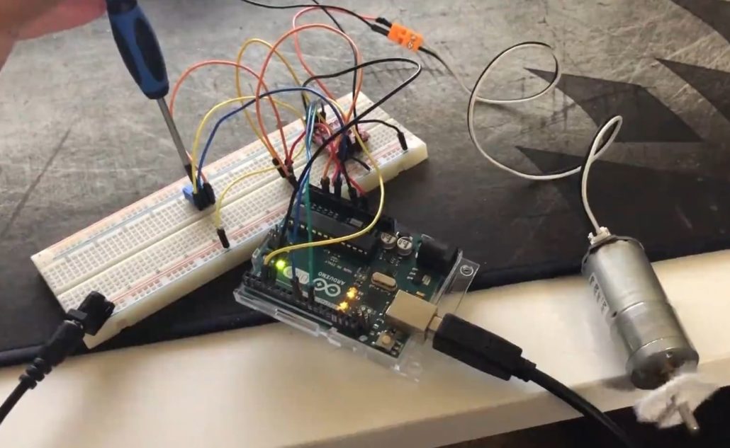
Figure 1: Breadboard Experiment 1
In this experiment, the ability to control the direction and speed of the 9V DC motor is shown. The direction of rotation of the motor is controlled by reading the state of a pin and the speed of the motor is controlled by reading the value of a potentiometer and translating it to a value between 0 and 255. The image shows the setup with the motor speed controlled by a potentiometer and the motors are powered by a 9V DC supply.The video in this link shows this process in action.
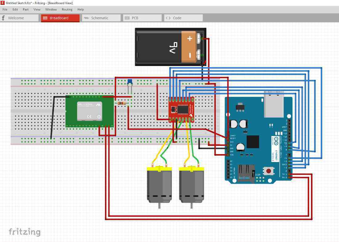
Figure 2: Fritzing diagram for the circuit used for experiment 1 and 2
The circuit shown above was used in experiment 2 and a slightly modified version in experiment 1. In experiment 1 only one motor was used and instead of the AIN1 and AIN2 pins on the motor driver being controlled by Bluetooth, they are controlled by the state of pin A1 being set high or low to change the direction of the motors. The PWMA pin is controlled by a potentiometer on pin A0 to control the speed of the motors. The rest of the connections are as shown above.
Experiment 2
This experiment was to test the functionality of the circuit in the previous experiment in the rapid prototype and the idle current draw of the system.
Components used in this experiment:
- Arduino Uno
- 9v DC 25mm motor (x2)
- 9V Energizer lithium battery
- HM-11 bluetooth module
- TB6612FNG motor driver
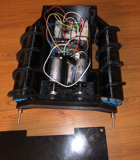
Figure 3: Breadboard Experiment 2
The circuit was built as shown above. The fritzing diagram in figure 2 was followed exactly to produce this circuit. The purpose of this was to verify the functionality of the Bluetooth communication and the ability of the robot to follow commands. The software used for this test was the ArxRobot basic sketch as it contained everything we needed to control the robot in all four directions. During this test we ran into a problem that would cause the robot to stop receiving any Bluetooth commands after the motor speed rises to a certain point. The Bluetooth module would stay on, and the app would stay connected but the robot would not react to any of the commands until the Arduino is reset. Initially a cheap 9V battery was used and after changing to a higher capacity battery the problem was fixed.
Experiment 3
Components used for this experiment:
- 5V DC power supply
- 6V metal gear motors
- Digital multi-meter
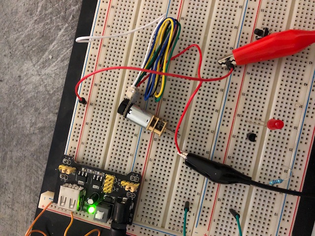
Figure 4: Breadboard Experiment 3
This final breadboard experiment was used to determine the current draw and speed of the motors using different voltage supplies. The metal gear motors are rated for 6V but the 3DoT board has a 650 mAh 3.6V battery which might cause the motors to slow down. Here the motors are tested with a 5V DC power supply and the show no significant loss of speed. More details about the current draw can be found in the Current Draw Testing Blog Post.
Software (Experiment 1)
Test.ino
//Breadboard Test code
//ScrewDriver
//Spring 2019
const int AIN1 = 3;     //PD0
const int AIN2 = 4;     //PD4
const int PWMA = 10;    //PD7
const int STBY = 8;     //PB5
const int Pot = A0;
const int Direction=A2;
void setup() {
  Serial.begin(9600);
  InitializeIO();       //Function to initailize IOs
  delay(200);
}

void loop() {
  digitalWrite(STBY,HIGH);
  int Dselect;
  Dselect=digitalRead(Direction); //Read state of pin to determine direction
  if (Dselect==0){
  digitalWrite(AIN1,LOW);
  digitalWrite(AIN2,HIGH);}
  else if (Dselect==1){
  digitalWrite(AIN1,HIGH);
  digitalWrite(AIN2,LOW);}
  int PotRead = 0;
  PotRead=analogRead(Pot);      //Read potentiometer
  int Motorspeed = 0;
  Motorspeed = map(PotRead, 0, 1023, 0, 255);
  analogWrite(PWMA,Motorspeed); //Write motorspeed at the PWM pin
  Serial.println(Dselect);
  delay(2);
    }
IO.ino
//This file contains intializations for all the IO pins
void InitializeIO() {
  pinMode(3,OUTPUT);
  pinMode(4,OUTPUT);
  pinMode(8,OUTPUT);
  pinMode(10,OUTPUT);
  pinMode(A0,INPUT);
  pinMode(A2,INPUT);
};
Conclusion
From these bread-boarding experiments we were able to confirm that the metal gear motors we selected will function properly with the 3.6V RCR123A battery on the 3DoT board without the need for an external battery. The metal gear motors are ideal because they show no significant speed loss even at 3.6V when they are rated for 6V and they have a relatively high rated torque of 0.7 kg.cm.
For the prototype experiments, the 9V battery was able to run the motors and the motor driver worked fine. From experiment 1 we were able to confirm the functionality of the circuit before building it fully and putting it on board the chassis of the prototype of the ScrewDriver as shown in experiment 2.