Servo Selection
By: Electronics and Control – Kevin Armentrout
Table of Contents
Servo Selection
Servo Selection Criteria
Servo Selection was based off of two requirements:
- An accuracy for the servo that is within 1 degree of set-point values
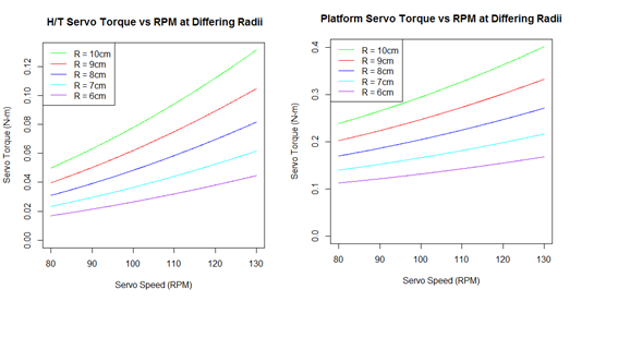
- Able to produce torque that is sufficient to actuate the position the servo will be placed
- Head/Tail Servo Torque: 18 – 45 mN-m
- Platform Servo Torque: 105 – 232 mN-m
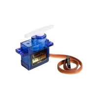
From these criteria, we also had the challenge of making the servo as small as possible to allow the components to fit in the form factor of the raptor’s chassis. This limited our selection to the smallest possible servo to meet the torque and precision requirements.
The SG 90 covers both the Head and Tail servo, as well as the platform servo for the desired torques that are needed to operate those actuators. Additionally, the SG90 servos are supplied for free to the project, allowing us to meet our budget.
Source Code
Servo and Motor
| # Determined by the Servo
stepSize = (pi/180)*(360/3000) thetaHead = seq(-pi/2,pi/2,stepSize) thetaTail = -thetaHead thetaLeg = seq(0,2*pi,stepSize) # In RPM MaxSpeed = seq(80,130,.1)
# Max Incline on Y Axis
MaxY = (6.5*pi/180)
# Centripital Acceleration # http://www.engineeringtoolbox.com/centripetal-acceleration-d_1285.html
A = (2*pi*MaxSpeed/60)^2 * Radius/100
# AA weight is 23g # AA dimensions are in cm, which is used to determine ABS plastic # Battery holder mass # http://data.energizer.com/PDFs/E91.pdf
innerLength = 5.050 innerWidth = 1.450 *2 innerHeight = 1.450
outerLength = innerLength + .5 outerWidth = innerWidth + .5 outerHeight = innerHeight + .5
HolderVolume = (outerLength * outerWidth * outerHeight) – (innerLength * innerWidth * innerHeight)
AA = 23 # ABS plastic weight is .97g/cc # http://www.stelray.com/reference-tables.html
ABSDensity = .97
# Calulate tail and head weight # Thickness of 1cm for consistant calculations
tailMass = 2*(AA) + (Radius*(1^2) + (HolderVolume)) *ABSDensity headMass = tailMass
# Previous Semester’s Robot Mass in grams # https://www.arxterra.com/spring-2016-velociraptor-project-summary/#Size_Weight
Mass = 657 BodyMass = Mass – tailMass – headMass
HeadPositionX = Radius*cos(thetaHead) HeadPositionY = Radius*sin(thetaHead)
TailPositionX = -Radius*cos(thetaTail) TailPositionY = -Radius*sin(thetaTail)
# For moments of mass
TailMassX = TailPositionX * tailMass TailMassY = TailPositionY * tailMass
HeadMassX = HeadPositionX * headMass HeadMassY = HeadPositionY * headMass
X_Moment = (TailMassX + HeadMassX) / (tailMass + headMass + BodyMass) Y_Moment = (TailMassY + HeadMassY) / (tailMass + headMass + BodyMass)
g = 9.8
LeverArm = max(Y_Moment) # Torque due to gravity (Y Axis)
MaxTorqueHeadY = (headMass/1000) * g * Radius/100 MaxTorqueTailY = (tailMass/1000) * g * Radius/100
# Realistic torque due to gravity
RealisticTorqueHeadY = MaxTorqueHeadY * sin(MaxY) RealisticTorqueTailY = MaxTorqueTailY * sin(MaxY)
# Torque due to Acceleration (X Axis)
MaxTorqueHeadX = (headMass/1000) * A * Radius/100 MaxTorqueTailX = (tailMass/1000) * A * Radius/100
# Platform Maximum Torque (Y Axis)
MaxTorquePlatform = MaxTorqueHeadY + MaxTorqueTailY + ((headMass/1000) * A * Radius/100) + ((tailMass/1000) * A * Radius/100)
# Frictionless Turning Torque
MaxTurningTorque = ((Mass/1000) * g) * LeverArm/100
# Frictionless Leg Moving Torque
MaxLegTorque = (Mass/2)/1000 * g * LegRadius/100 LegTorque = abs(MaxLegTorque * sin(thetaLeg)) RealMaxLegTorque = abs(MaxLegTorque * sin(60/180 * pi))
|
Calcs Addendum
| Radius1 = 2
Radius2 = 1.5*Radius1 Radius3 = 2.25*Radius1
RPM = 32 w1 = seq(from = 0, to = -2*pi, by = -2*pi/360) w2 = c(seq(from = 0, to = -(4/3)*pi, by = -(4/3)*pi/(2*length(w1)/3)),seq(from = -(4/3)*pi, to = -2*pi, by = -(2/3)*pi/(1*length(w1)/3))) w2 = w2[1:length(w1)+1] – 4*pi/3 w3 = c(seq(from = 0, to = -(4/3)*pi, by = -(4/3)*pi/(2*length(w1)/3)),seq(from = (4/3)*pi, to = 0, by = -(2/3)*pi/(1*length(w1)/3))) w3 = w3[1:length(w1)+1] – 5*pi/6
# ABS plastic weight is .97g/cc # http://www.stelray.com/reference-tables.html
ABSDensity = .97
# Other side is roughly a quarter of scaling factor in length massR2 = .5*(Radius2 * .25) * ABSDensity
# Other side is roughly a one and a half quarter of scaling factor in length massR3 = .5*(Radius3 * 1.5) * ABSDensity
# Other side is roughly a quarter of lever arm length mass = 657 bodyMass = mass/2 – 2*(massR2 + massR3)
# Centripital Acceleration # http://www.engineeringtoolbox.com/centripetal-acceleration-d_1285.html
A2 = (2*pi*RPM/60)^2 * Radius2/100 A3 = (2*pi*RPM/60)^2 * Radius3/100
g = 9.8
LegTorque1 = (bodyMass)/1000 * g * Radius1/100 * sin(w1) LegTorque2 = ((massR2)/1000 * g * Radius2/100) + ((bodyMass)/1000 * g * Radius2/100 * sin(w2)) LegTorque3 = ((massR3)/1000 * g * Radius3/100) + ((bodyMass)/1000 * g * Radius3/100 * sin(w3))
LegTorque = (LegTorque1 + LegTorque2 + LegTorque3) plot(w1, LegTorque, col = “black”, type = “o”, pch = NA, lty = 1, lwd = 2, ylab = “Torque (N-m)”, xlab = “Primary Lever Arm Position (Radians)”, main = “Leg Torque Versus Lever Arm Position”) AverageLT = mean(LegTorque) TorqueForCurrent = LegTorque TorqueForCurrent[TorqueForCurrent < 0] = 0
wTip = seq(pi/2, 0,(-pi/2)/360) TipOverTorque = 6.5/100 * g * (BodyMass/2-2*(massR2 + massR3))/1000 plot(MaxSpeed,2*MaxTorqueHeadX10, cex = .75, ylim = c(0,2*max(MaxTorqueHeadX10)), pch = “.”, col = “green”, xlab = “Servo Speed (RPM)”, ylab = “Servo Torque (N-m)”, main = ” H/T Servo Torque vs RPM at Differing H/T Radii”) lines(MaxSpeed,2*MaxTorqueHeadX9, pch = “.”, col = “red”) lines(MaxSpeed,2*MaxTorqueHeadX8, pch = “.”, col = “blue”) lines(MaxSpeed,2*MaxTorqueHeadX7, pch = “.”, col = “orange”) lines(MaxSpeed,2*MaxTorqueHeadX6, pch = “.”, col = “brown”) lines(MaxSpeed,rep(TipOverTorque,length(MaxTorqueHeadX7)),col = “black”) legend(“topleft”, cex =.75, lty =c(1,1,1,1,1,1), lwd = c(1,1,1,1,1,1), col = c(“green”,”red”,”blue”,”orange”,”brown”,”black”), legend = c(“R = 10cm”,”R = 9cm”,”R = 8cm”,”R = 7cm”,”R = 6cm”, “Tip Over Torque”))
thetaPlatform = seq(-6.5*pi/180, 6.5*pi/180, 1/360) HeadPlatformPositionZ7 = 7*sin(thetaPlatform) TailPlatformPositionZ7 = -7*sin(thetaPlatform) HeadPlatformPositionZ6 = 6*sin(thetaPlatform) TailPlatformPositionZ6 = -6*sin(thetaPlatform) HeadPlatformPositionZ8 = 8*sin(thetaPlatform) TailPlatformPositionZ8 = -8*sin(thetaPlatform) HeadPlatformPositionZ9 = 9*sin(thetaPlatform) TailPlatformPositionZ9 = -9*sin(thetaPlatform) HeadPlatformPositionZ10 = 10*sin(thetaPlatform) TailPlatformPositionZ10 = -10*sin(thetaPlatform)
plot(HeadPlatformPositionZ10, thetaPlatform*180/pi, cex = .75, xlim = c(min(TailPlatformPositionZ10),max(HeadPlatformPositionZ10)), type = “o”, pch = NA, col = “green”, xlab = “Head and Tail Position Z Axis (cm)”, ylab = “Platform Inclination (degrees)”, main = “H/T Position vs Inclination Angle”) lines(HeadPlatformPositionZ9, thetaPlatform*180/pi, pch = “.”, col = “red”) lines(HeadPlatformPositionZ8, thetaPlatform*180/pi, pch = “.”, col = “blue”) lines(HeadPlatformPositionZ7, thetaPlatform*180/pi, pch = “.”, col = “orange”) lines(HeadPlatformPositionZ6, thetaPlatform*180/pi, pch = “.”, col = “brown”) lines(TailPlatformPositionZ10, thetaPlatform*180/pi, pch = “.”, col = “green”) lines(TailPlatformPositionZ9, thetaPlatform*180/pi, pch = “.”, col = “red”) lines(TailPlatformPositionZ8, thetaPlatform*180/pi, pch = “.”, col = “blue”) lines(TailPlatformPositionZ7, thetaPlatform*180/pi, pch = “.”, col = “orange”) lines(TailPlatformPositionZ6, thetaPlatform*180/pi, pch = “.”, col = “brown”) legend(“topleft”, cex =.75, lty =c(1,1,1,1,1,1), lwd = c(1,1,1,1,1,1), col = c(“green”,”red”,”blue”,”orange”,”brown”), legend = c(“R = 10cm”,”R = 9cm”,”R = 8cm”,”R = 7cm”,”R = 6cm”))
ADC = seq(0,3.3,.00080) ADC = c(ADC, rep(3.3, length(ADC)*(1/12))) ADCRad = seq(0,2*pi, 2*pi/length(ADC)) ADCRad = ADCRad[1:length(ADCRad)-1] plot(ADCRad, ADC, col = “black”, type = “l”, pch = NA, lty = 1, lwd = 2, ylab = “ADC Voltage (V)”, xlab = “Primary Lever Arm Position (Radians)”, main = “A/D Voltage Versus Shaft Position”)
|