Spring 2016 A-TeChToP 3D Printed Case
By Mimy Ho (Manufacturing Engineer)
Introduction
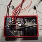
We received the PCB back from the manufacturer in 2 weeks, soldering the PCB was done by the Manufacturing Division a week later. And we finally have the completed PCB, the next step is to design the 3D printed case for housing the PCB and battery.
Table of Contents
Requirement
The size of the case has to be less than the size of an iPhone 6 [1].
| Dimension | Length | Width | Thickness |
| I-phone 6 | 138.1mm | 67.0mm | 6.9mm |
The Design Process
- Determined dimension of the case
The printed case will be housing the PCB and the battery. We decided to use 3 AA battery holder for 3 LiFePO4 batteries. The table below explain in detail about the dimension of the case.
| Dimension | Length | Width | Thickness |
| PCB | 64mm | 61.5mm | 20mm |
| Battery holder | 49mm | 61.5mm | 19mm |
| Inner | 113mm | 61.5mm | 20mm |
| Outer | 117mm | 65.5mm | 20mm |
Note: The thickness of the case is determined based on the height 1000µF capacitor. The image below shows the completed PCB with the 1000µF capacitor’s size dominant.
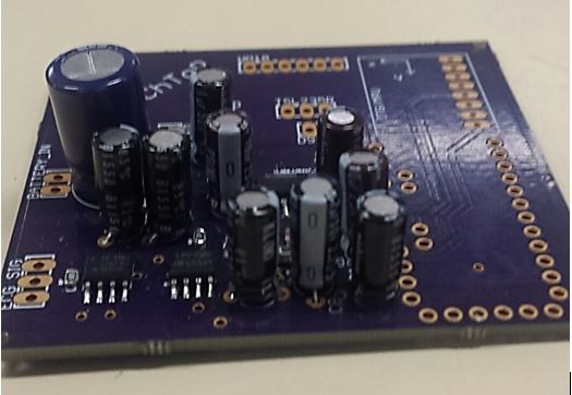
Figure 1: The completed PCB
- Determined connection PCB to the electrodes and sensors (Figure 2)
On the top of the case, there are 4 holes with 7mm diameter each. One is for the pulse sensor including 3 wires, one is for the LED with 2 wires, one is for the infrared LED with 2 wires, and one is for the blood oximeter sensor with 3 wires.
On the left side of the case, there is a hole with 3mm diameter for connecting the left electrode to the PCB.
On the right side of the case, there are 3mm diameter holes: one connects the right electrode to the PCB; one connects the temperature sensor to the PCB
On the bottom of the case, there is another hold with 3mm diameter for connecting the electrode to the PCB.
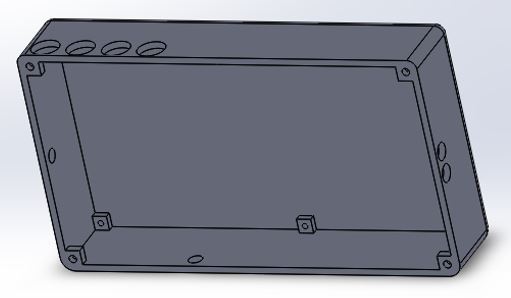
Figure 2: View of the holes of the case
- Mounting
The cover of the case will be closed by using M2 x 5mm screws. Also, inside the side there are the gaps 2mm with drill holes 0.086in (M2 x 5mm) for mounting the PCB to the case.
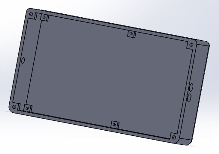
Figure 3: Mounting holes for the cover and PCB
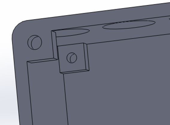
Figure 4: Close-up of the mounting holes
Finalized Design
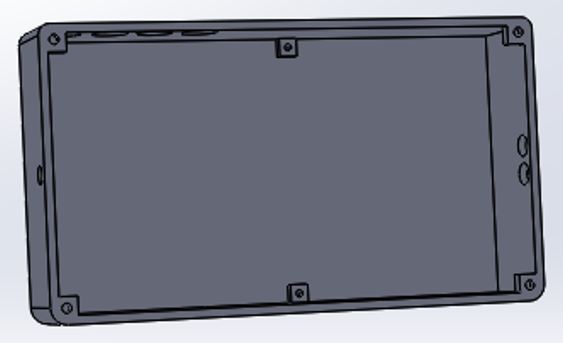
Figure 5: The 3D printed case
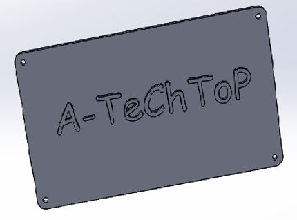
Figure 6: The 3D printed cover
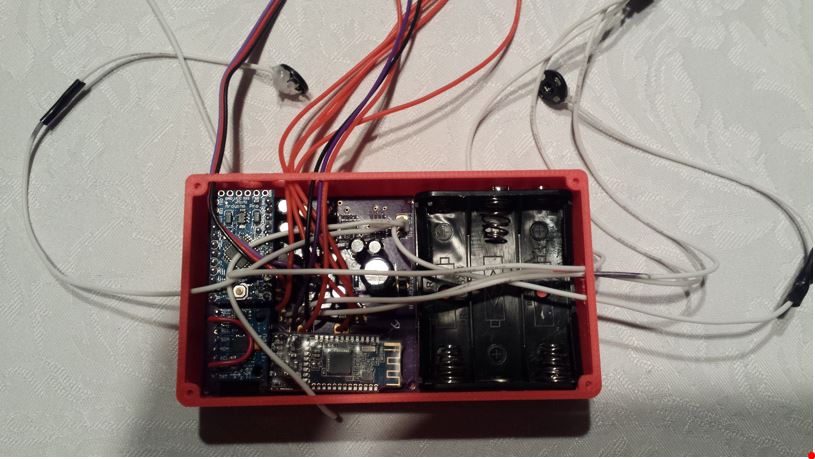
Figure 7: The completed case with the PCB and battery holder
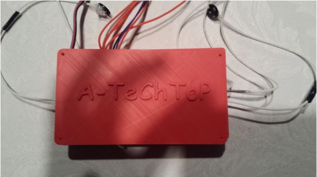
Figure 8: The completed case with the cover.
Conclusion
The 3D printed case meets the length and width requirement; however, the thickness was triple the thickness of the I-phone 6. Since the case design is based on the PCB and the battery holder, the printed case is the best option that we achieve at this moment.
Reference
[1] http://www.gsmarena.com/apple_iphone_6-6378.php