Spring 2016 Velociraptor: Bluetooth & Arxterra
By : Camilla Nelly Jensen (Systems Engineer)
In order to meet the project level 2 requirement 13 for the Velociraptor, the Bluetooth module shall be connected to the microcontroller to establish a wireless communication with the Arxterra application that is installed on an android device. Below are the instructions on how to establish this communication.
1.Download Arxterra application to Android device
- Follow instruction from Getting Started: Arxterra Control Panel & Android Applications powerpoint on how to access to Arxterra Android Application and installing it to the android device.
- Obtain permission to access the Arxterra Application from Mr. Jeff Gomes.
2. Build Bluetooth configuration on breadboard
- According to the System Recourse Map, the HC-06 Bluetooth module is connected to the following pins on the Arduino microcontroller:
- HC-06 Ground (GND) pin to Arduino ground(GND).
- HC-06 power (Vcc) pin to Arduino 5 V – To power Bluetooth module.
- HC-06 TX/TXD pin to Arduino digital pin 0 (RX)- to transmit data from Arxterra app to MCU(Velociraptor).
- HC-06 RX/RXD pin to Arduino digital pin 1 (TX)- for Arxterra app to receive data from MCU(Velociraptor).
- The STATE and EN pins will not be used.
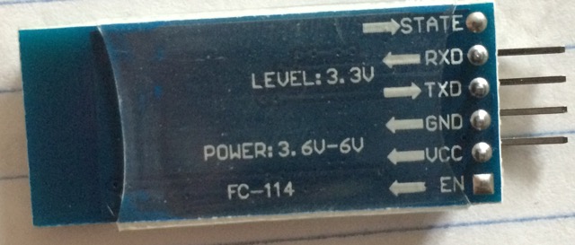
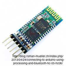
Figure 1:
Figure 1 displays the Bluetooth module that will be used to establish the wireless communication to the robot. On the Bluetooth module, the RXD and TXD pins are used for sending and receive data. The module operates at 3.6V to 5V. Receiving data via the RXD pin operate at 3.3V from Arduino.
Receiving data via the RXD line on the Bluetooth module from the Arduino can potentially burn the device. The Arduino transmits a higher voltage than the Bluetooth module can handle, therefore, modification needs to be done. The TX line of the Arduino transmits a voltage at 5V to the receiving pin RXD on the Bluetooth module, however, the RXD pin can only be operated at 3.3V. By implementing a voltage divider, this will drop the voltage to 3.3V coming into the RXD pin of the Bluetooth device and thus, protects it from being damaged.
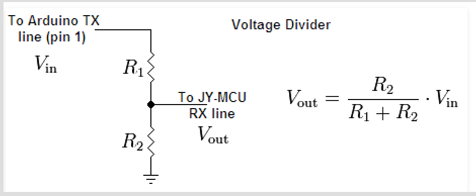
Figure 2: Voltage Divider Equation – credit to 42 Bots
Figure 2 displays how the voltage divider is set up in order reduce the voltage from TX to the RXD pin of the Module.
The Bluetooth module uses 3 x 10k ohm resistors in series and the calculations are shown below in figure 3:
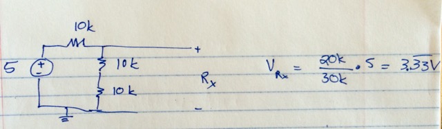
Figure 3: Voltage divider calculations for Velociraptor
3. Establish Bluetooth connection between Android device and Arduino
The Bluetooth schematic on the breadboard is shown in figure 4.

Figure 4: Bluetooth setup
- The Bluetooth module uses the Arduino IDE code which has the latest version of the Arxrobot firmware. The codes can be downloaded from Github.
- Under the Arxrobot_firmware tab, you find the code to upload to the Arduino, to be able to connect to the Bluetooth module that is connected to the Arduino Microcontroller

Figure 5
- The Bluetooth module utilizes the code above in figure 5 to connect to the Arduino. This code is uploaded to the Arduino microcontroller to recognize the serial communication with the Bluetooth module.
- The Bluetooth is connected to the Arduino which is powered by a computer. The Bluetooth module’s red LED blinks when the module is turned on, the LED stop blinking when communication with Android device is established.
- To pair the module with the Android device go to Settings >> Bluetooth and select the HC-06 module and type in the default pairing code: 1234.
- In the Arxterra application, ARXROBOT the Bluetooth symbol on the top right corner is selected and tap connect to the paired device the Bluetooth module HC-06.
- Once the communication is successfully established; the Bluetooth symbol on the top right corner of the ARXROBOT app turned blue (white when there is no connection) and the red status LED on the Bluetooth module stop blinking. The established communication is shown in figure 4 where the red status LED is on.
4. Confirm Bluetooth communication by turning on 4 LEDS on the breadboard via the joystick on the Arxterra app
The Velociraptor shall be able to walk forward and turn when the robot detects obstacles in order to avoid a collision. Therefore, the joystick on the ARXROBOT qualifies as the best solution for control pad as it provides four buttons of control. The joystick that’s made up of four buttons makes its possible to attach one command to each button, ie. four commands: forward, turn left, turn right and backward. However, the 4th button is not necessary, as we don’t intend to implement a backward walking command. In order to access the four different buttons, a simple code turning on four LEDS was written in the Arduino IDE, so that the forward button in Arxterra app will turn on LED attached to pin 8 and so on. This test was made so that the Electronic engineer decode the signal into subcommands of move forward, turn to either side etc.
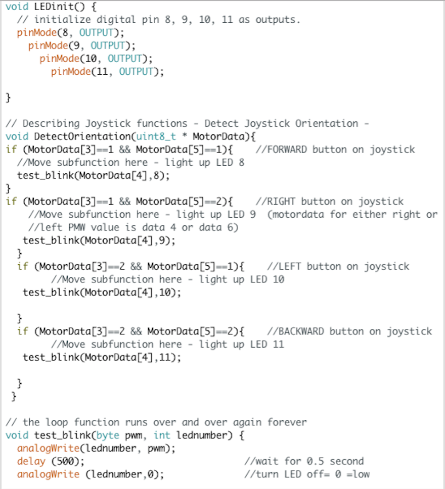
Figure 6
Figure 6 displays the Arduino IDE code that will control each LED by one of the four buttons on the joystick on the Arxterra app in the order of:
- Forward button will turn on LED attached to pin 8
- Right button will turn on LED attached to pin 9
- Left button will turn on LED attached to pin 10
- Back button will turn on LED attached to pin 11
Note: Before uploading the code to the Arduino remember to detach the Bluetooth module from the breadboard as it will interfere with the upload and causes error. Re-attach when the code finishes uploading.
Click here for the video showing the communication between the Bluetooth and the Arxterra Application.
References:
- http://www.docfoc.com/getting-started-arxterra-control-panel-android-applications-create-an-account-connect-on-app-log-in-to-control-panel-tommy-sanchez-ee400d
- http://42bots.com/tutorials/hc-06-bluetooth-module-datasheet-and-configuration-with-arduino/
- http://42bots.com/tutorials/how-to-connect-arduino-uno-to-android-phone-via-bluetooth/
- http://www.amazon.com/JBtek-Bluetooth-Converter-Serial-Communication/dp/B00L08GA4Q/ref=sr_1_1?s=pc&ie=UTF8&qid=1456784518&sr=1-1&keywords=Hc.+06+bluetooth+module+for+arduino