Spring 2016 Velociraptor: Updated Block Diagrams
By: Camilla Nelly Jensen (Systems Engineer)
For the System Design, the Active Control Circuit for the software blocks of the dynamic walk was missing and thus that circuit has been updated along with the rest of the system block diagrams for the Velociraptor in this blog post. Likewise, the interface matrix has been updated in order to show leftover available pins of the microcontroller.
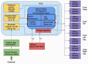
Figure 1: Updated System Block Diagram
The system block diagram displayed in figure 1 shows the interface connections of the inputs (Arxterra application) and outputs (servos) of the Velociraptor. For the updated version both sensors, ultrasonic and accelerometer and Bluetooth module have been mounted on the PCB along with the microcontroller, some directly into the pins of the microcontroller in order to minimize the use of wires to establish connections. Since microcontroller requires voltage input of 7-12 V, two batteries in series (3.7V*2=7.4V) have been placed on the head to provide that. The other two batteries have similarly been placed in series on the tail but as the servos require an input voltage of 6V the batteries have been connected to a voltage regulator to downsize the 7.4 V to match the 6V for the servos. The location of the batteries has been chosen to minimize the weight on the body of the robot.
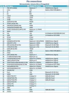
Figure 2: Interface matrix
Figure 2 shows the components of the Velociraptor’s pin connections and the leftover available pins on the Arduino Micro Atmega32U4 microcontroller board. The interface matrix hasn’t changed much from the PDR since we decided to go with the original components after testing other components. This comprises testing of the accelerometer where the first objective was to use the MPU-6050 3 Axis Gyro Accelerometer Sensor for the Velociraptor to detect an incline. But after testing the accuracy of the gyro-accelerometer is showed an error of 1-2° degrees and took up too much memory of the microcontroller and thus the group decided to go back to the original accelerometer ADXL335 that detected inclines more accurate and takes up less memory. Likewise, with an ultrasonic sensor the first intent was to utilize the HC-SR04 Ultrasonic Ranging Sensor but during tests, the sensor would loose signal and thus not valid to use for the Velociraptor to detect obstacles. Therefore, the group decided to change to the MB1030 LV-MaxSonar-EZ3 Ultrasonic Rangefinder, which operated to the accuracy listed in the datasheet and did not loose signal. The ultrasonic sensor is, therefore, the only component that has been changed for the setup and the LV-MaxSonar-EZ3 utilizes one pin less than the HC-SR04 only a TRIG pin.
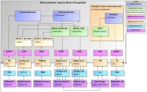
Figure 3: Active control circuit for statically walk
The software block diagram in figure 3 shows how the input command is sent via the Bluetooth module and through what pinouts to reach the Arduino firmware blocks to be decoded and handled before sent as subroutines to the output components, the servos to act the subroutines sent. The sensors, ultrasonic and accelerometer also gives inputs to the subroutines of the servos and thus if the ultrasonic sensor detects an obstacle the input routine shall block the MOVE subroutine for the servos. Likewise with the input from the accelerometer, if it detects an incline, an input routine will be sent to the servos subroutine and change the subroutine (walking code) in order to adjust to the incline.
For the Velociraptor, we are only sending commands from the Arxterra application to the servos to perform and not receiving any data from the components to the Arxterra application. The orange example box on the left shows how telemetry/data from the batteries could have been implemented and handled; the status of how much power the batteries have left could have been remotely sent back to the Arxterra application via the Bluetooth’s receive (RXD) channel in order to keep a real-time track of when to recharge the batteries.
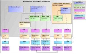
Figure 4: Active control circuit for Dynamic walk


