HeroBot Spring 2021
LDC Sensor PCB design
Author: Christopher Villanueva
Table of Contents
Introduction
The HeroBot team’s project involves having the HeroBot (using Humans for Robots’ Paperbot kit) maneuver through a maze. While maneuvering through the maze, HeroBot must reach the designated “key” square before exiting via its designated exit. One of the requirements for the Maze Project is that the robot must traverse the maze without passing over any boundaries. In order to fulfill this requirement, the team has decided to utilize a metal detection using copper tape and an LDC sensor for contactless metal detection.
Previous projects from past semesters have utilized metal dection in order to incorporate line-following using a strip of inductive material for the robot to follow. The HeroBot will not be a line-following robot, but rather it will avoid the inductive material, as the inductive material (in our team’s case, copper tape) will be used to define the boundaries of the maze rather than the path the robot can take. During the design process, the final decision for the LDC sensor to be used in the navigations systems for HeroBot is the LDC1612 Inductance-to-Digital Converter. The design process of the PCB as well as the decision to use the LDC1612 over other LDC sensors will be discussed in this post.
Testing the LDC1612
Before designing the PCB for the LDC1612, first a breakout board was purchased for testing. The breakout board our team decided upon for the LDC sensor was the Grove – 2-Channel Inductive Sensor (LDC1612)1. This sensor is based off of the LDC1612, which at the time of our team purchasing it was not exactly the final decision on the sensor. The store page for the Grove sensor additionally included Eagle files (schematic and board) and a software library for testing the sensor. This software library included .h and .cpp files for utilizing the sensor as well as example code for single channel sensing, multi-channel sensing, and code that tells the user how far away a coin is from the sensor.
Using the included software and the Grove sensor, the metal detection capabilities of the sensor are tested. For the purpose of this project, our team wants the sensor to be able to detect copper tape that is stuck underneath the walls of the maze.

Figure 1. Results from using the Grove sensor to detect copper tape underneath the maze.
From the above figure, a set of obtained values from the Grove sensor using the basic_demo code included in the software library are seen. These values were typically in the 4.4 or 4.5 million range; 4.4 when the sensor was not near the copper tape and 4.5 when the sensor was above the copper tape.
PCB Design Iterations
In this section, the process of designing the custom PCB to be used with HeroBot will be discussed. The document from TI “LDC Sensor Design”2 details the process of designing the LDC sensor, the coils to be utilized with the sensor, and additionally compares various different LDC sensors with each other so that the correct sensor can be used.
Coil Design
The previously mentioned LDC Sensor Design document does detail the coil design process, however in order to simplify the process, the Webench Coil Designer provided by TI was used instead, which has the user input the properties of a desired coil then generates a .brd file with the designed coil. Using this tool, the below coil was generated.
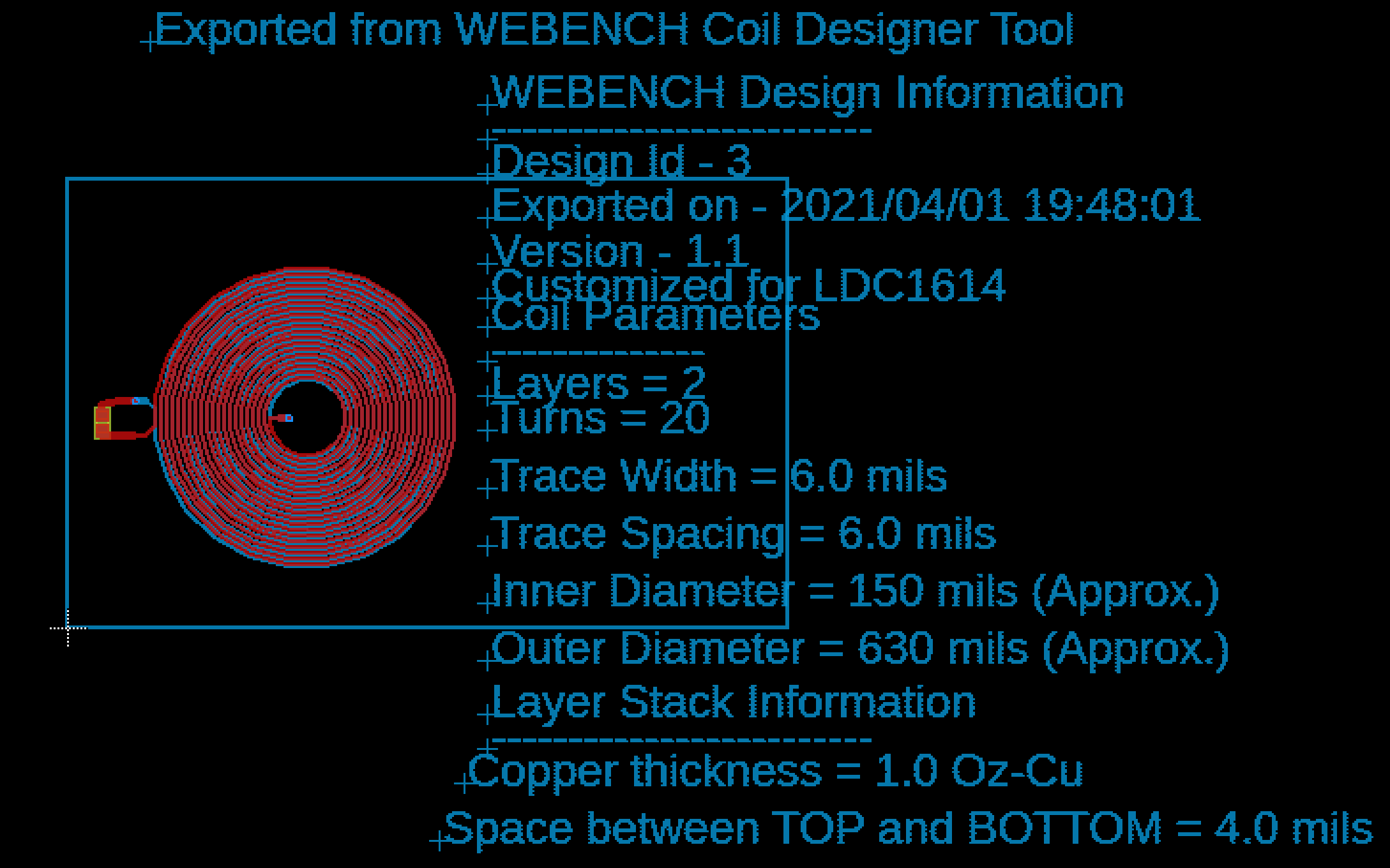
Figure 2. Coil generated by Webench Coil Designer to be used in HeroBot
Adding the coil to the PCB design proved to be difficult at first. For some reason, the coil could not be copied onto the sensor PCB; Eagle only returned a “No back-annotation” error. Seeking an alternative, the Coils ULP, which is already implemented into Eagle, was tried. The process of using the ULP still proved to be tedious, so the Webench tool was returned to. This time however, copying the coil into the PCB worked without issue. It is unknown why it worked this time but failed before. The process of adding the coil to the PCB design simply involved highlighting the entire coil, copying it, opening up the .brd file for the custom PCB, then pasting it.
First Iteration
Having verified that the LDC sensor would suit HeroBot’s purposes for navigation, a PCB using the LDC1614 (rather than the LDC1612) was decided upon. This is because the LDC1614 essentially is the same as the LDC1612 except that it has four channels for sensing rather than just two. This was an important factor in the design of the PCB because three coils in total were planned to be used for navigation; two coils to detect both sides of the robot and a third coil for the sole purpose of distinguishing walls in front of the robot. The design was based off of the schematic for the Grove sensor, however various components were removed. Such components removed included unnecessary voltage regulators, jumpers, and transistors. Additionally, the LDC1612 of the Grove sensor was swapped out for the LDC1614.
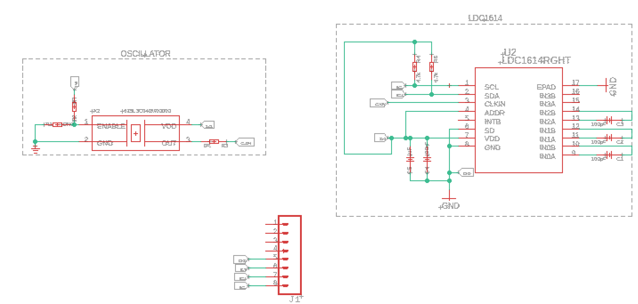
Figure 3. Schematic for the LDC1614 PCB using 3 coils.

Figure 4. Image of the .brd file for the 1st iteration PCB
Several glaring issues exist with this design. The PCB was designed so that the coils would be above the walls to detect them. This design did not account for the robot possibly drifting to either side; it would not be able to detect if the robot began to veer into the walls. Additionally, the actual coils implemented into the design do not exist in the schematic. This oversight caused the connection between the coils and their capacitor sensors to be seen by Eagle as overlap errors, as the coils did not exist in the schematic. In addition to these errors, there existed several other DRC and overlap errors.
Second Iteration
Taking into account the issues of the first iteration of the PCB, a second iteration was developed. In this iteration, the issue of the sensor not being able to detect if the robot begins to drift off-course was remedied by moving the coils within the walls of the maze; in other words, rather than being above the walls of the maze, both coils were within them. This way, rather than detecting the walls and following them, the sensor would detect that the robot was coming into contact with the wall and can be programmed to avoid it. Additionally, the coils were added into the schematic file, thus eliminating the error that saw the connections between the capacitor sensors and the coils as overlaps.
As the coils were now much closer together due to being moved within the maze, the third coil had to be removed. Since only two coils were being used, the LDC1614 was switched to an LDC1612. Since this third coil was used to detect front walls within the maze, there was no quick and easy solution that could be achieved with the design. As such, the use of QRE1113 IR sensors was permitted for the purpose of detecting walls and black lines within the maze. In order to create more room on the board, the oscillator was also deemed unnecessary, as the LDC1612’s datasheet3 explicitly states that an external oscillator is optional, as the sensor does have an internal one.
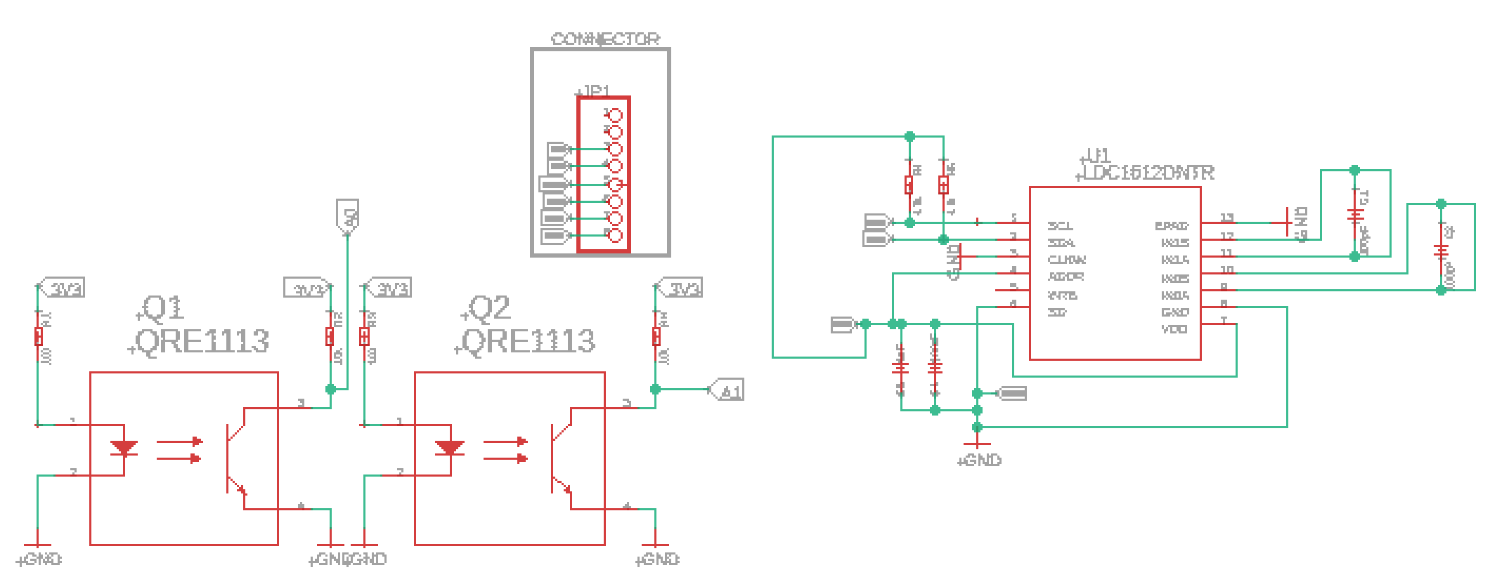
Figure 5. Schematic for the second iteration of the custom PCB
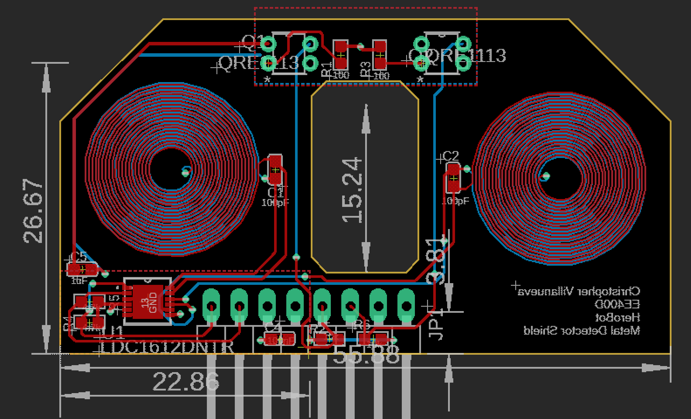
Figure 6. Board layout of the second iteration custom PCB.
This iteration is close to the desired outcome, but there still exists an oversight; the hole in the middle of the board was not wide enough to fit the ball caster included in the 3DoT Paperbot kit. Another iteration of the board was necessary to fix this issue.
Third Iteration
The main thing being changed in this iteration of the board was the size of the hole in the center of the second iteration. In order to accomplish this, the both of the coils had to be rotated so that their sensor capacitors were underneath them, as opposed to being on the side. This allowed ample room to be made to accommodate the ball caster. No changes were made to the schematic.
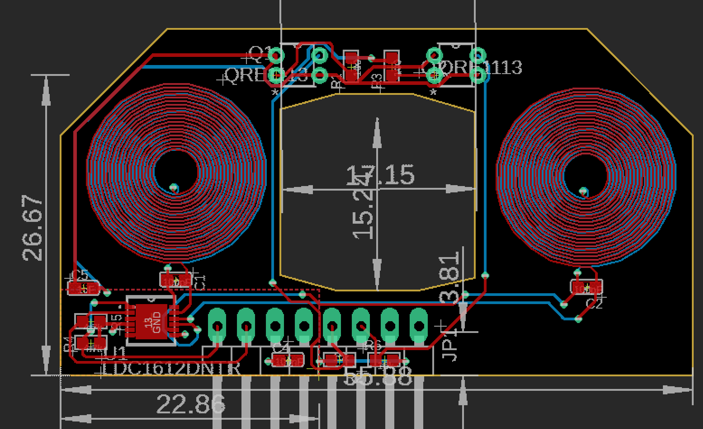
Figure 7. Board Layout of the third iteration of the custom PCB.
Finished and Assembled PCB
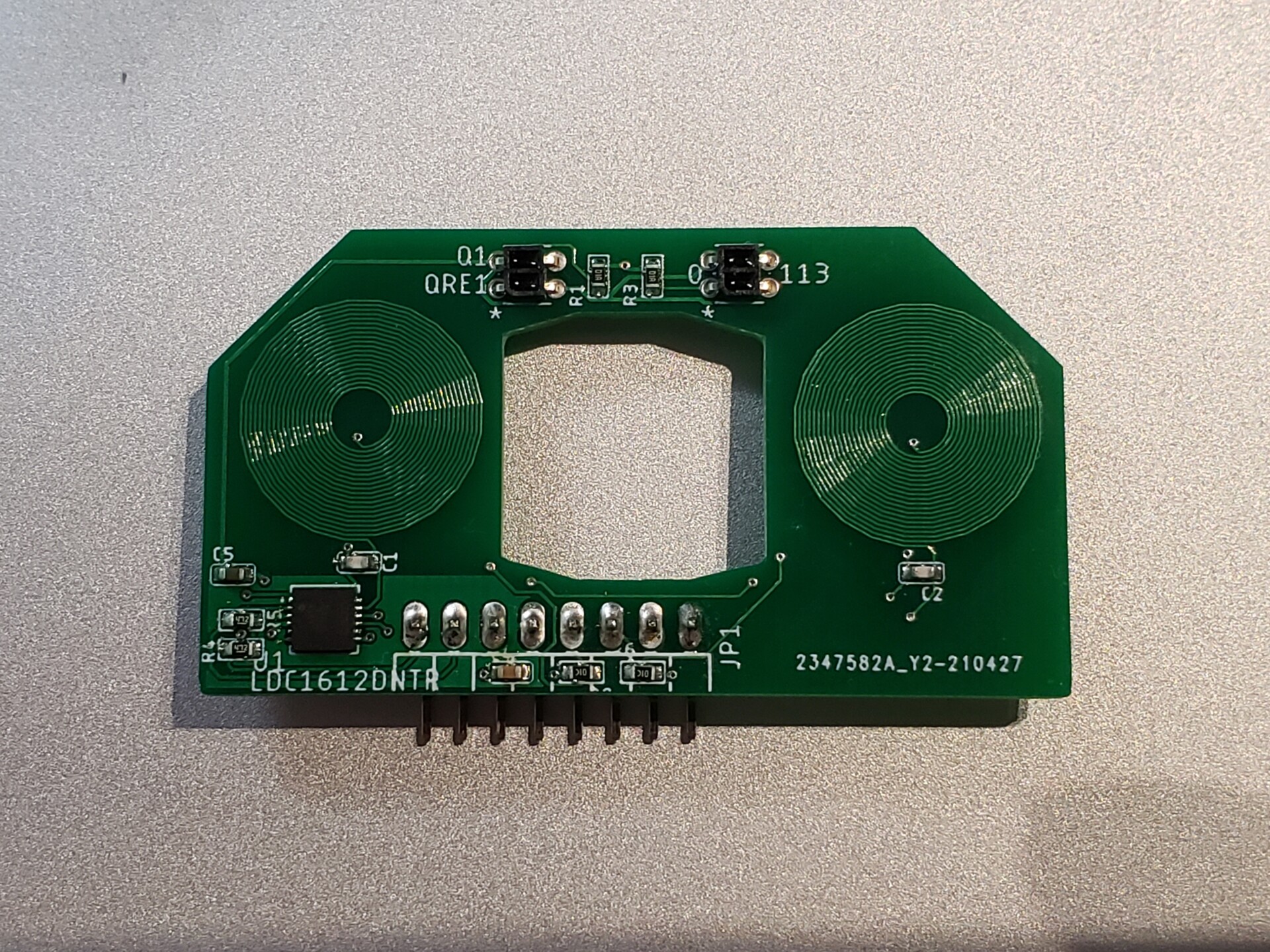
Fig 8. Completed and assembled PCB
With the third iteration design complete and approved, the design was sent to JLCPCB manufacturer and ordered, as well as the components. A small hot plate was used to solder this PCB together, along side a stencil ordered alongside the boards.
Conclusion
With the assembly of the PCB, metal detection capabilities of the robot have been enabled. The most prominent issue with assembling the board was inexperience; for example, the actual size of the components had not been considered, and when opening the packaging two capacitors were immediately lost. Additionally, when soldering the LDC1612 to the board, the traces were much closer together than expected. This was overcome however by letting the solder reflow first before placing the LDC chip on the board, as this allowed for possible shorts or bridging to be seen before the placement of the chip.