Pathfinder Solar Array Spring 2019
Test and Breadboarding
Author/s: Wilder Pineda (Electronics and Control)
Verification: Guitron, Brendan (Project Manager)
Approval: Guitron, Brendan (Project Manager)
Table of Contents
Introduction
Before creating our active and passive PCBs, we had to breadboard our electronic designs. This allowed us to see if our initial design works. We used the program Fritzing to help guide each breadboard design.
Passive Panel (Fritzing)
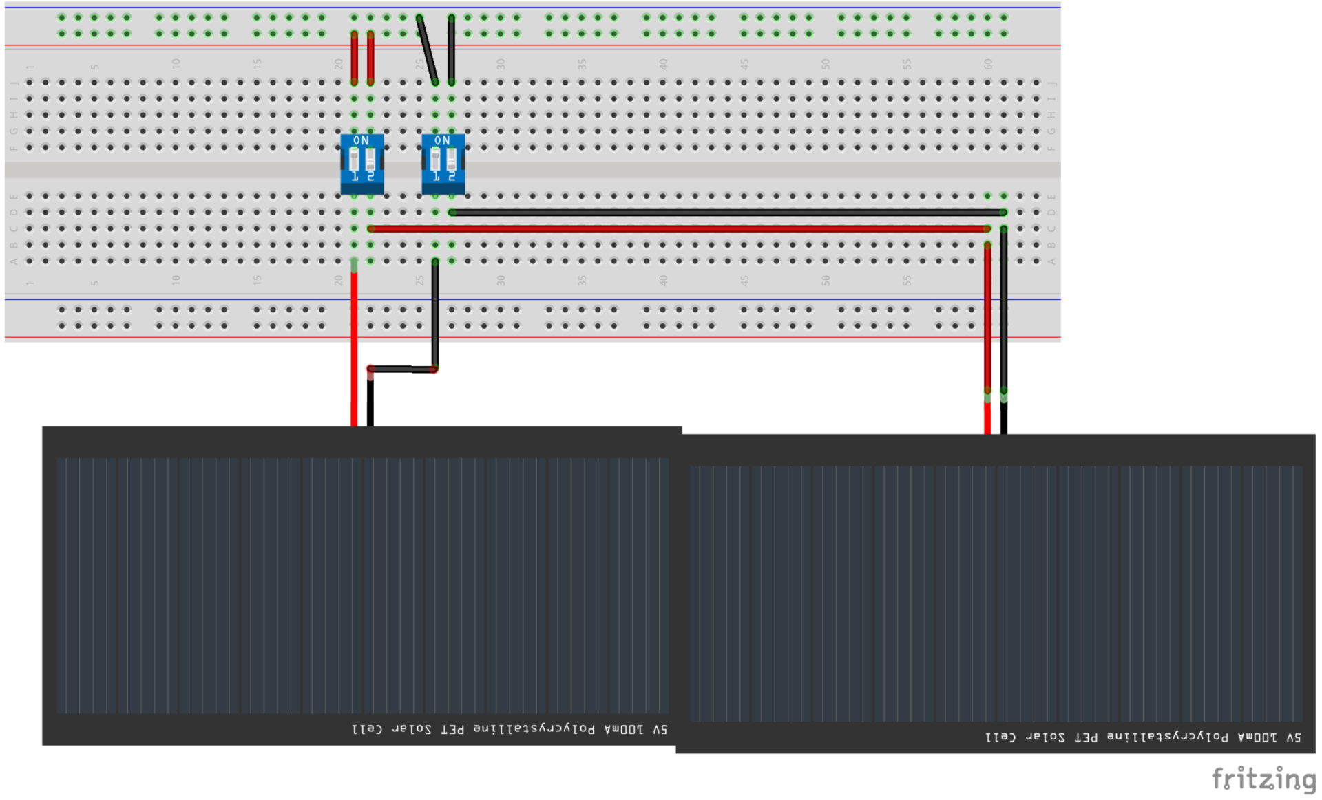
Figure 1: Passive Panel
The passive panel separates the positive and negative leads of the solar cell and feeds it into a 4 pin dip switch. The configuration of the 4 dip switches defines whether its passive panel is first or second in the series connection.
Active Panel (Fritzing)
The active panel includes an ATtiny85 and an INA169. The contents obtain the readings for voltage and current of the solar module and sends that data via I2C to the Arduino Uno.
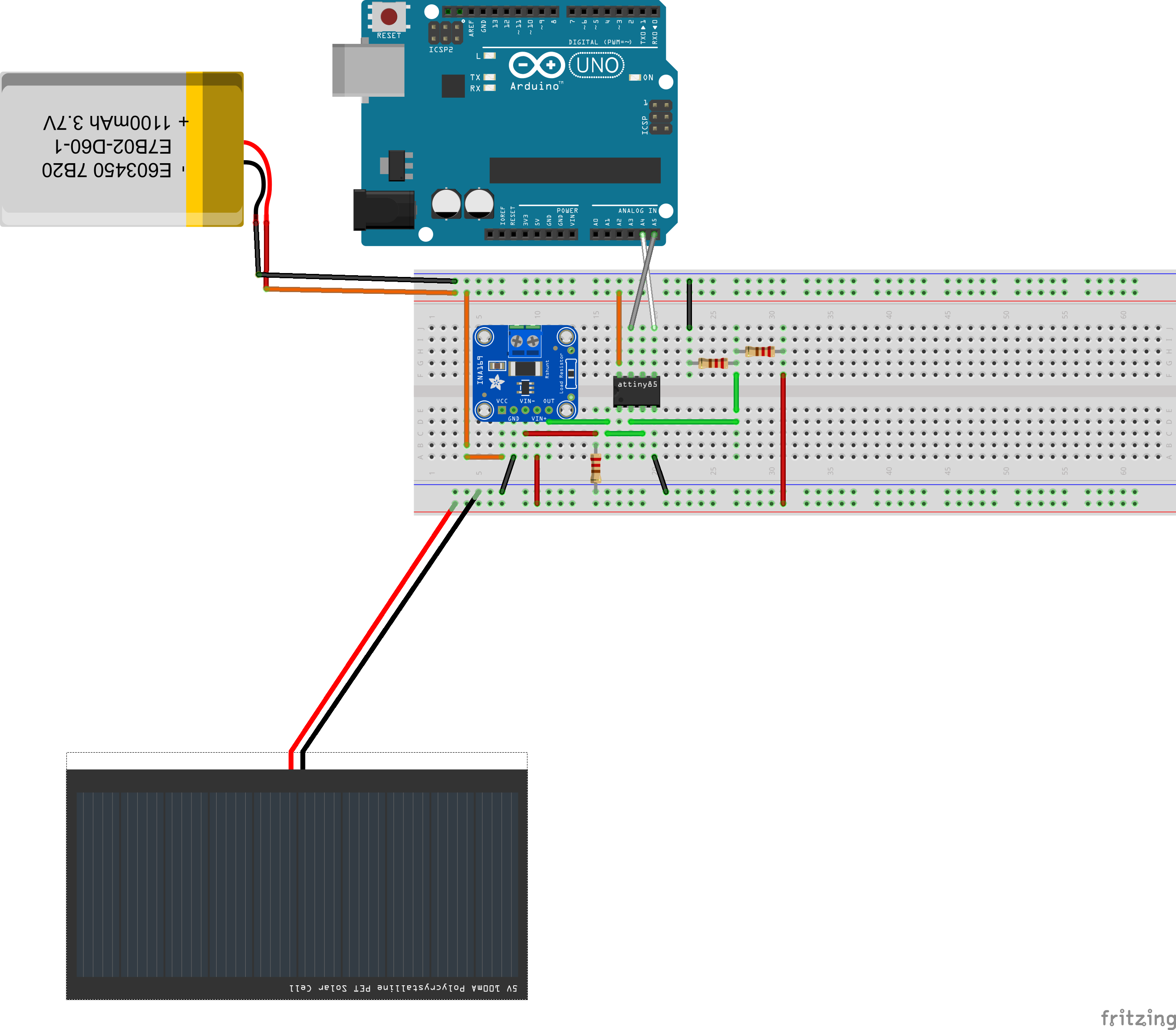
Figure 2: Active Panel
Solar Cells
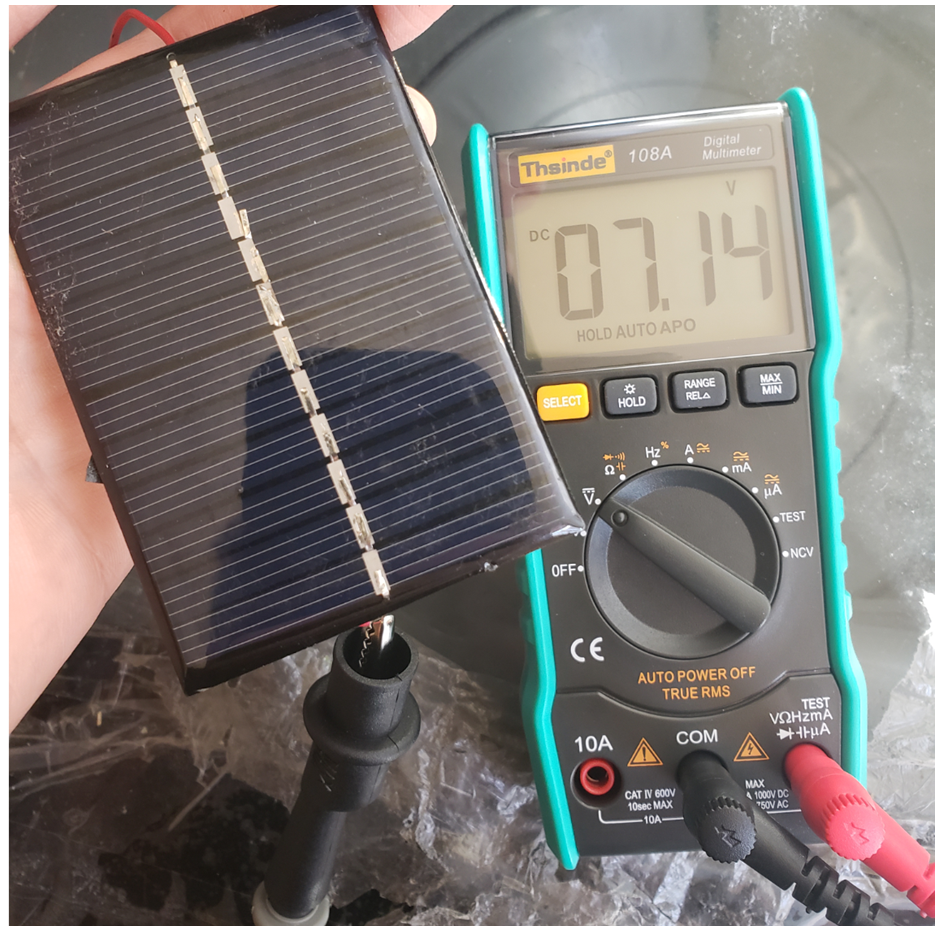
Figure 3: Voltage of single solar cell

Figure 4: Voltage of 1 module (3 solar cells in series)

Figure 5: Current of module (3 in series)
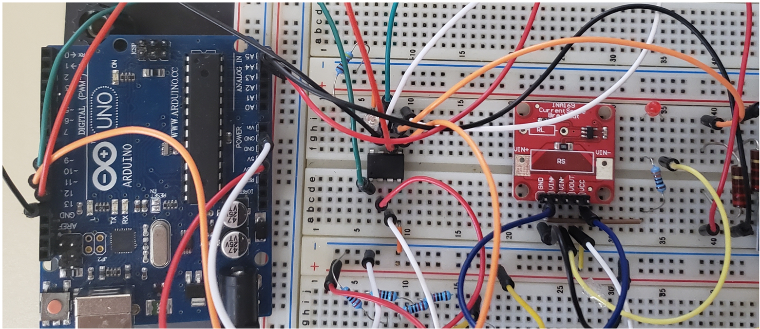
Figure 6: Bread Board
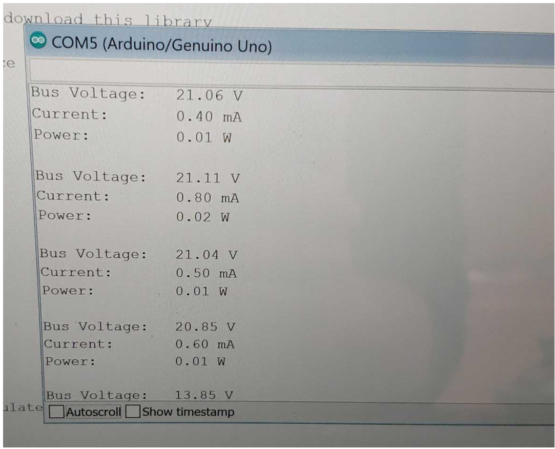
Figure 7: Serial port
Wire Voltage Loss
In order to see which wires would be the most suitable for the design, we calculated the voltage loss using an online calculator. Below are the voltage drops.
26AWG:
voltage from solar panels: 22.5 V
voltage drop: 0.4480%
voltage out: 22.3992V

24AWG:
voltage from solar panels: 22.5 V
voltage drop: 0.4097%
voltage out: 22.4078V

22AWG:
voltage from solar panels: 22.5 V
voltage drop: 0.2924%
voltage out: 22.4342V
References/Resources
- Fritzing: http://fritzing.org/home/
- INA169: http://www.ti.com/lit/ds/symlink/ina169.pdf
- ATtiny85: https://ww1.microchip.com/downloads/en/DeviceDoc/Atmel-2586-AVR-8-bit-Microcontroller-ATtiny25-ATtiny45-ATtiny85_Datasheet.pdf
- Arduino Uno: https://ww1.microchip.com/downloads/en/DeviceDoc/Atmel-2586-AVR-8-bit-Microcontroller-ATtiny25-ATtiny45-ATtiny85_Datasheet.pdf
- Voltage Loss Calculator: https://www.calculator.net/voltage-drop-calculator.html