Color Sensor Shield: Fabrication, Integration, and Test
Approved By: Muhannad Al Mohamed, Charles Banuelos, Melwin Pakpahan
Written By: Muhannad Al Mohamed
Table of Contents
Color Sensor Shield Parts and Design
The parts used in the fabrication of each color sensor shields are the printed circuit board, electronic parts(two color sensors (BH1745NUC-E2), two LEDs (0603 package), two 150 Ohms resistors (0603 package), one 10k resistor (0603 package), one 47k resistor (0603 package), two 0.1 uF capacitors (0603 package), one MOSFET, one pin header), and Color Sensor Shield’s stencils along with solder.
Update: 12/6/2017
The design of the Color Sensor Shield is done using the free EagleCAD software. The schematics file of the circuit is attached to this link. The Printed Circuit Board layout is attached to this link. To open files the EagleCAD software needs to be installed.
Fabrication Place and Equipment
The fabrication of the CSS (Color Sensor Shield) is currently taking place in ET-111 room. The room is equipped with a microscope that can help in placing the parts on the shield. It also has an oven that can be used to melt the solder on the shield to hold the solder in place. Other useful amenities are available in the room such as a fridge to keep the solder cooled and ready to be used, and scissors and tape that can be used to hold the shield in one spot to place parts.
Fabrication and Integration Process
The fabrication process starts with holding the shield in one place and apply solder to it. Some unused PCBs are used to hold the shield in the center with duck tape applied to it.
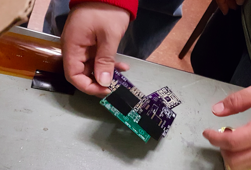
Placing CSS in the centre of other PCBs to hold it
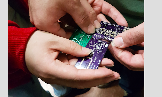
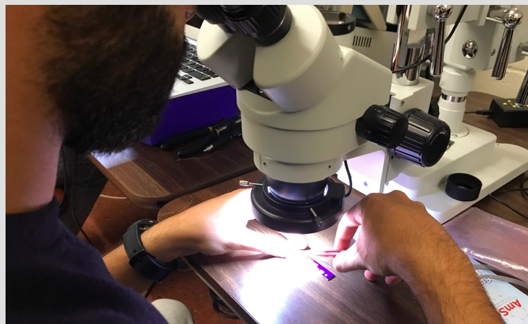
Solder is then placed on the board with a stencil on top of it using a card to evenly spread the solder. The microscope is then used to check if enough solder is applied to the PCB’s pads. Parts are then placed on the shield using tweezers to carefully put each part on the exact corresponding place.
Placing parts using tweezers
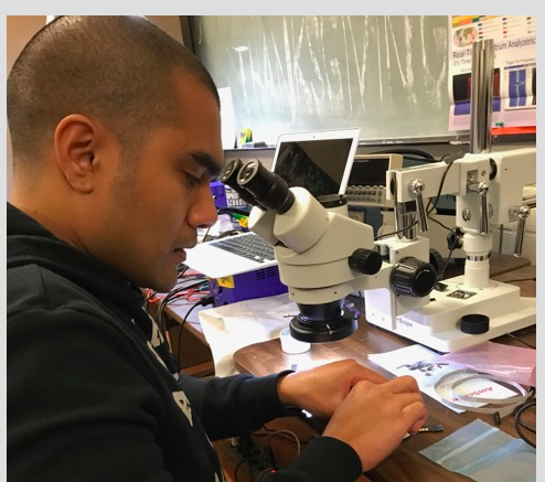
Checking if parts placed correctly
After making sure that the parts are placed on the correct place by looking at the shield through the microscope, the shield is then placed in the oven to let the solder flow and melt to make the connection to the parts.
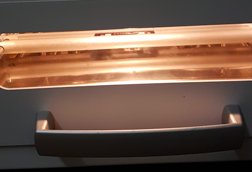
Cooking the CSS in the oven
Since the CSS has parts placed on the top and bottom of it, only one side, of the shield, parts will be placed on put in the oven. The other parts on the other side will be placed and soldered by hand.
Final Product
Update: 12/6/2017
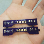
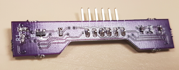
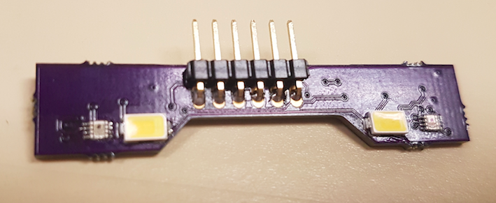
We were able to fabricate four shields with the parts provided.
Color Sensor Shield Top View
Color Sensor Shield Bottom View
Testing Process
The CSS will be tested once a fabrication of on shield is done. The shield will be connected to a 3DoT board and the I2C addresses would be checked. Codes of reading values within the registers in the Color Sensor IC should be applied to CSS through programming the 3DoT board.
Update: 12/6/2017
The first test on the shields was an inspection to locate any bridges present on the surface mount pads or dislocation of parts. If any bridges or dislocation are present, the shields would be fixed by desoldering the parts with a heat gun and soldering them again in place. By visual testing, we found that two shields had their LEDs light on and the other two were not functioning. Therefore, pin testing was done to check if the LEDs and the Color Sensor ICs had power in them. Surprisingly all the pins had power in them, therefore, any misfunctions could not be seen visually.
After checking that all parts are in place, the address checking code is applied to the Color Sensor Shield to make sure that the two sensors have the addresses of (0x38) and (0x39).
Another testing method to see if the Color Sensor Shields are actually working is by applying an Arduino code that uses the I2C library to read data from a register within the Color Sensor IC. The code attached reads data from the register that holds the value of the Red color.
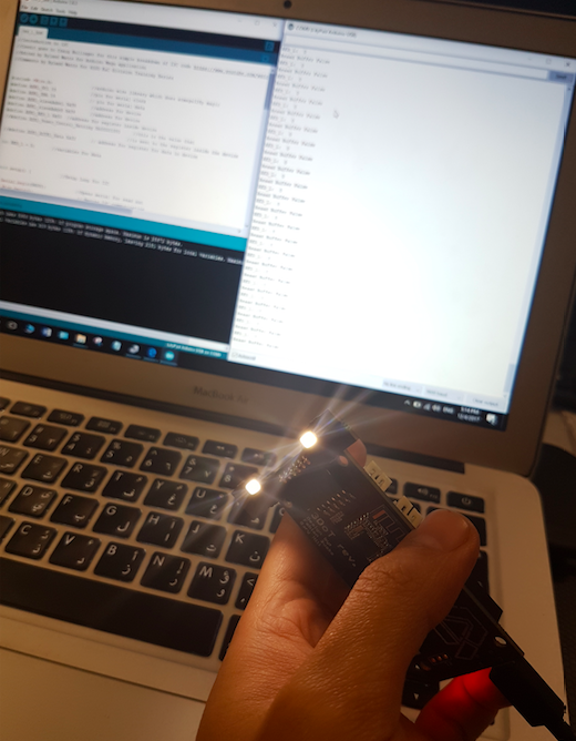
Reading data from a register on the Color Sensor
This code was unable to read data from the Color Sensor Shield so another code is used. This code is optimized to measure colors from the color sensor shield.
Measurements
The measurements taken was applied by using a green surface with different locations.
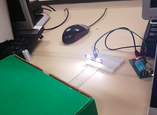
Taking measurements of the color sensor shield
Perpendicular alignment of the measured surface to the color sensor shield
- No change in green 115 at 13.5cm
- at 9.5 cm, still 115
- at 5.5cm, still 115
- at 3.5cm, changed to 138
- at 4.5cm, changed to 120
- at 5cm, changed to 122
- at 2 cm, changed to 192
- at 1.5cm, changed to 259
Horizontal alignment of the measured surface to the color sensor shield
- at 10cm, no detection
- at 6cm, no detection
- at 4cm, no detection
- at 2cm, no detection
- at 0.5, detection of 122
After taking measurements, we have concluded that the furthest distance for the color sensor to sense colors are 2cm perpendicularly and 0.5cm horizontally.
Final Deliverables
Update: 12/15/2017
After testing all Color Sensor Shields (CSS), there were no functional shields that can be accurately used to take measurements of colors in the maze. Two of the shields did not have a functional LEDs due to the burning of some parts during fabrication. The other two boards had functional LED but only one color sensor on one board was functional. The other color sensor on that board was intermittent and could not be relied upon for accurate measurements.
The possible reasons for the failure of producing functional Color Sensor Shields are solder bridges created during the soldering process and burnt parts during the repair process. The bridges could have been created during the placement of the parts on the board which was done by hand instead of using the pick and place machine or during the baking process to solder the parts to the board. The burning of extra parts occurred during the repair of certain parts that did not solder to the board. A heat gun had to be used to repair the boards which would cause surface burns and ultimate destruction of parts.